Gold's Gym 705 ZLT . PETL79810.0 User manual
- Category
- Treadmills
- Type
- User manual
This manual is also suitable for

Serial Number
Decal
Model No. GGTL90608.0
Serial No.
CAUTION
Read all precautions and instruc-
tions in this manual before using
this equipment. Save this manual
for future reference.
QUESTIONS?
As a manufacturer, we are com-
mitted to providing complete cus-
tomer satisfaction. If you have
questions, or if parts are missing,
DO NOT CONTACT THE STORE;
please contact Customer Care.
IMPORTANT: You must note the
product model number and
serial number (see the drawing
above) before contacting us:
CALL TOLL-FREE:
1-877-776-4777
Mon.–Fri. 6 a.m.–6 p.m. MT
Sat. 8 a.m.–4 p.m. MT
ON THE WEB:
www.workoutwarehouse.com
Write the serial number in the space
above for reference.
USER'S MANUAL

TABLE OF CONTENTS
WARNING DECAL PLACEMENT . . . . . . . . . . . . . . . . . . . . . . . . . . . . . . . . . . . . . . . . . . . . . . . . . . . . . . . . . . . . . .2
IMPORTANT PRECAUTIONS . . . . . . . . . . . . . . . . . . . . . . . . . . . . . . . . . . . . . . . . . . . . . . . . . . . . . . . . . . . . . . . .3
BEFORE YOU BEGIN . . . . . . . . . . . . . . . . . . . . . . . . . . . . . . . . . . . . . . . . . . . . . . . . . . . . . . . . . . . . . . . . . . . . . .5
A
SSEMBLY . . . . . . . . . . . . . . . . . . . . . . . . . . . . . . . . . . . . . . . . . . . . . . . . . . . . . . . . . . . . . . . . . . . . . . . . . . . . . . .6
OPERATION AND ADJUSTMENT . . . . . . . . . . . . . . . . . . . . . . . . . . . . . . . . . . . . . . . . . . . . . . . . . . . . . . . . . . . .12
HOW TO FOLD AND MOVE THE TREADMILL . . . . . . . . . . . . . . . . . . . . . . . . . . . . . . . . . . . . . . . . . . . . . . . . . .20
TROUBLESHOOTING . . . . . . . . . . . . . . . . . . . . . . . . . . . . . . . . . . . . . . . . . . . . . . . . . . . . . . . . . . . . . . . . . . . . .22
EXERCISE GUIDELINES . . . . . . . . . . . . . . . . . . . . . . . . . . . . . . . . . . . . . . . . . . . . . . . . . . . . . . . . . . . . . . . . . . .25
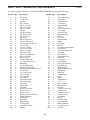
PART LIST . . . . . . . . . . . . . . . . . . . . . . . . . . . . . . . . . . . . . . . . . . . . . . . . . . . . . . . . . . . . . . . . . . . . . . . . . . . . . .26
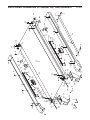
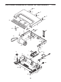
EXPLODED DRAWING . . . . . . . . . . . . . . . . . . . . . . . . . . . . . . . . . . . . . . . . . . . . . . . . . . . . . . . . . . . . . . . . . . . .28
ORDERING REPLACEMENT PARTS . . . . . . . . . . . . . . . . . . . . . . . . . . . . . . . . . . . . . . . . . . . . . . . . . .Back Cover
LIMITED WARRANTY . . . . . . . . . . . . . . . . . . . . . . . . . . . . . . . . . . . . . . . . . . . . . . . . . . . . . . . . . . . . . .Back Cover
This product is manufactured and distributed under license from Gold's Gym Merchandising, Inc.
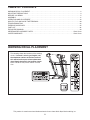
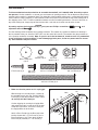
This drawing shows the locations of the warning
decals. If a decal is missing or illegible, call
the telephone number on the front cover of
this manual and request a free replacement
decal. Apply the decal in the location shown.
Note: The decals may not be shown at actual
size.
WARNING DECAL PLACEMENT
2

3
1. Before beginning any exercise program, con-
sult your physician. This is especially impor-
tant for persons over the age of 35 or persons
with pre-existing health problems.
2. It is the responsibility of the owner to ensure
that all users of this treadmill are adequately
informed of all warnings and precautions.
3. Use the treadmill only as described.
4. Place the treadmill on a level surface, with at
least 8 ft. (2.4 m) of clearance behind it and 2
ft. (0.6 m) on each side. Do not place the
treadmill on any surface that blocks air open-
ings. To protect the floor or carpet from dam-
age, place a mat under the treadmill.
5. Keep the treadmill indoors, away from mois-
ture and dust. Do not put the treadmill in a
garage or covered patio, or near water.
6. Do not operate the treadmill where aerosol
products are used or where oxygen is being
administered.
7. Keep children under the age of 12 and pets
away from the treadmill at all times.
8. The treadmill should be used only by persons
weighing 300 lbs. (136 kg) or less.
9. Never allow more than one person on the
treadmill at a time.
10. Wear appropriate exercise clothes when
using the treadmill. Do not wear loose clothes
that could become caught in the treadmill.
Athletic support clothes are recommended
for both men and women. Always wear ath-
letic shoes. Never use the treadmill with bare
feet, wearing only stockings, or in sandals.
11. When connecting the power cord (see page
12), plug the power cord into a surge sup-
pressor (not included) and plug the surge
suppressor into a grounded circuit capable of
carrying 15 or more amps. No other appliance
should be on the same circuit. Do not use an
extension cord.
12. Use only a single-outlet surge suppressor that
meets all of the specifications described on
page 12. To purchase a surge suppressor, see
your local GOLDʼS GYM dealer or call the tele-
phone number on the front cover of this man-
ual and order part number 146148, or see your
local electronics store.
13. Failure to use a properly functioning surge
suppressor could result in damage to the con-
trol system of the treadmill. If the control sys-
tem is damaged, the walking belt may change
speed, accelerate, or stop unexpectedly,
which may result in a fall and serious injury.
14. Keep the power cord and the surge suppres-
sor away from heated surfaces.
15. Never move the walking belt while the power
is turned off. Do not operate the treadmill if
the power cord or plug is damaged, or if the
treadmill is not working properly. (See TROU-
BLESHOOTING on page 22 if the treadmill is
not working properly.)
16. Read, understand, and test the emergency
stop procedure before using the treadmill (see
HOW TO TURN ON THE POWER on page 14).
17. Never start the treadmill while you are stand-
ing on the walking belt. Always hold the
handrails while using the treadmill.
18. The treadmill is capable of high speeds.
Adjust the speed in small increments to avoid
sudden jumps in speed.
19. The pulse sensor is not a medical device.
Various factors, including the user's move-
ment, may affect the accuracy of heart rate
readings. The pulse sensor is intended only
as an exercise aid in determining heart rate
trends in general.
WARNING: To reduce the risk of serious injury, read all important precautions and in-
s
tructions in this manual and all warnings on your treadmill before using your treadmill. ICON as-
sumes no responsibility for personal injury or property damage sustained by or through the use of
this product.
IMPORTANT PRECAUTIONS

4
2
0. Never leave the treadmill unattended while it
is running. Always remove the key, unplug
the power cord, and switch the reset/off cir-
cuit breaker to the off position when the
treadmill is not in use. (See the drawing on
page 5 for the location of the circuit breaker.)
21. Do not attempt to raise, lower, or move the
treadmill until it is properly assembled. (See
ASSEMBLY on page 6, and HOW TO FOLD
AND MOVE THE TREADMILL on page 20.)
You must be able to safely lift 45 lbs. (20 kg)
to raise, lower, or move the treadmill.
22. When folding or moving the treadmill, make
sure that the storage latch is holding the
frame securely in the storage position.
23. Never insert any object into any opening on
the treadmill.
2
4. Inspect and properly tighten all parts of the
treadmill regularly.
25.
DANGER: Always unplug the power
cord immediately after use, before cleaning the
treadmill, and before performing the mainte-
n
ance and adjustment procedures described in
this manual. Never remove the motor hood un-
less instructed to do so by an authorized ser-
vice representative. Servicing other than the
procedures in this manual should be performed
by an authorized service representative only.
26. This treadmill is intended for in-home use
only. Do not use this treadmill in a commer-
cial, rental, or institutional setting.
SAVE THESE INSTRUCTIONS

5
T
hank you for selecting the revolutionary GOLDʼS
GYM MAXX™ COMPETITOR 1080 treadmill. The
COMPETITOR 1080 treadmill offers an impressive
array of features designed to make your workouts at
h
ome more enjoyable and effective. And when youʼre
not exercising, the unique treadmill can be folded up,
requiring less than half the floor space of other tread-
mills.
For your benefit, read this manual carefully before
using the treadmill. If you have questions after read-
ing this manual, please see the front cover of this man-
u
al. To help us assist you, note the product model
number and serial number before contacting us. The
model number and the location of the serial number
decal are shown on the front cover of this manual.
To avoid a registration fee for any service needed
under warranty, you must register the treadmill at
www.workoutwarehouse.com/registration.
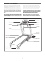
Before reading further, please review the drawing
below and familiarize yourself with the labeled parts.
BEFORE YOU BEGIN
Handrail
Upright
Pulse Sensor
Key/Clip
Reset/Off
Circuit Breaker
Walking Belt
Platform Cushion
Foot Rail
Power Cord
Rear Roller
Adjustment Bolts
Console
Book Holder
Accessory Tray

6
ASSEMBLY
T
o hire an authorized service technician to assemble the treadmill, call 1-800-445-2480. Assembly requires
two persons. Set the treadmill in a cleared area and remove all packing materials. Do not dispose of the packing
materials until assembly is completed. Note: The underside of the treadmill walking belt is coated with high-perfor-
mance lubricant. During shipping, a small amount of lubricant may be transferred to the top of the walking belt or
t
he shipping carton. This is a normal condition and does not affect treadmill performance. If there is lubricant on
top of the walking belt, simply wipe off the lubricant with a soft cloth and a mild, non-abrasive cleaner.
Assembly requires the included hex keys and your own Phillips screwdriver and
adjustable wrench .
Use the drawings below to identify the assembly hardware. The number in parentheses below each drawing is
the key number of the part, from the PART LIST near the end of this manual. The number after the parentheses
is the quantity needed for assembly. Note: If a part is not in the hardware kit, check to see if it is preattached
to one of the parts to be assembled. To avoid damaging plastic parts, do not use power tools for assem-
bly. Extra hardware may be included.
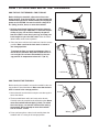
1. Make sure that the power cord is unplugged.
With the help of a second person, carefully tip
the treadmill onto its left side. Partially fold the
Frame (56) so that the treadmill is more stable;
do not fully fold the Frame yet.
Cut the shipping tie securing the Upright Wire
(38) to the Base (83). Locate the tie in the indi-
cated hole in the Base, and use the tie to pull
the Upright Wire out of the hole.
Attach a Base Pad (81) to the Base (83) in the
location shown with a 1" Tek Screw (2) and a
Base Pad Spacer (13). Then, attach another
Base Pad (81) with only a 1" Tek Screw (2).
83
2
56
81
3/8" Nut (8)–3
1" Tek Screw (2)–4
Base Pad Spacer
(13)–2
3/8" Star
Washer (9)–7
1/4" Star
Washer (10)–6
3/8" x 4 1/2" Bolt (6)–4
3/8" x 2" Bolt (4)–3
1/4" x 1/2"
Bolt (7)–6
3/8" x 1 1/4" Bolt (5)–3
1
81
2
38
Hole
13

7
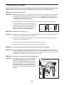
3. Identify the Right Upright (78) and the Right
Upright Spacer (79), which are marked with
stickers. Insert the Upright Wire (38) through the
Right Upright Spacer as shown. Set the Right
Upright Spacer on the Base (83).
Have a second person hold the Right Upright (78)
near the Base (83). See the inset drawing. Tie
the wire tie in the Right Upright securely around
the end of the Upright Wire (38). Then, pull the
other end of the wire tie until the Upright Wire is
routed completely through the Right Upright.
83
38
78
79
38
3
2
. Remove the 3/8" Nut (8) and the 3/8" x 2" Bolt
(4) from the Base (83). Attach a Wheel (84) with
t
he Bolt and the Nut that you just removed. Do
not overtighten the Nut; the Wheel must turn
freely.
C
ut the tie off the Upright Wire (38).
83
3
8
Tie
4
8
2
84
Wire
Tie
78
38
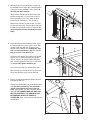
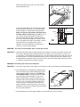
4. Hold a Bolt Spacer (80) inside the lower end of
the Right Upright (78). Insert a 3/8" x 4 1/2" Bolt
(6) with a 3/8" Star Washer (9) into the Right
Upright and the Bolt Spacer. Repeat this step
with a second Bolt Spacer (80), 3/8" x 4 1/2"
Bolt (6), and 3/8" Star Washer (9).
Hold the Right Upright (78) against the Right
Upright Spacer (79). Be careful not to pinch
the Upright Wire (38). Partially tighten the 3/8"
x 4 1/2" Bolts (6); do not fully tighten the
Bolts yet.
Press a Base Endcap (77) into the Base (83).
79
78
38
9
77
80
80
6
4
83
Wire
Tie

8
6. Hold a Bolt Spacer (80) inside the lower end of
the Left Upright (74). Insert a 3/8" x 4 1/2" Bolt
(6) with a 3/8" Star Washer (9) into the Left
Upright and the Bolt Spacer. Repeat this step
with a second Bolt Spacer (80), 3/8" x 4 1/2"
Bolt (6), and 3/8" Star Washer (9).
Orient the Left Upright (74) and the Left Upright
Spacer (76) as shown. Hold the Left Upright
Spacer and the Left Upright against the Base
(83). Partially tighten the two 3/8" x 4 1/2" Bolts
(6); do not fully tighten the Bolts yet.
Press a Base Endcap (77) into the Base (83).
With the help of a second person, tip the tread-
mill so that the Base (83) is flat on the floor.
76
74
6
83
80
80
77
9
6
5. With the help of a second person, carefully tip
the treadmill onto its right side. Partially fold the
Frame (56) so the treadmill is more stable; do
n
ot fully fold the Frame yet.
Attach a Base Pad (81) to the Base (83) in the
location shown with a 1" Tek Screw (2) and a
Base Pad Spacer (13). Then, attach another
Base Pad (81) with only a 1" Tek Screw (2).
Remove the 3/8" Nut (8) and the 3/8" x 2" Bolt
(4) from the Base (83). Attach a Wheel (84) with
the Bolt and the Nut that you just removed. Do
not overtighten the Nut; the Wheel must turn
freely.
5
8
3
84
56
4
8
81
2
81
13
2
7. Have a second person hold the Bridge (95) near
the Right Upright (78).
Connect the Upright Wire (38) to the Bridge Wire
(52). See the inset drawing. The connectors
should slide together easily and snap into
place. If they do not, turn one connector and try
again. IF THE CONNECTORS ARE NOT CON-
NECTED PROPERLY, THE CONSOLE MAY
BE DAMAGED WHEN THE POWER IS
TURNED ON. Then, remove the wire tie from the
Upright Wire.
78
95
52
Wire Tie
7
38
38
52

9
8. Insert the indicated connectors into the Right
Upright (78).
Next, insert the fronts of the brackets on the
B
ridge (95) into the Uprights (74, 78), and then
fully insert the brackets. Make sure that the
plastic edges of the Bridge are inside the
Uprights.
Attach the Bridge (95) with six 1/4" x 1/2" Bolts
(7) and six 1/4" Star Washers (10); start all six
Bolts before tightening any of them.
See steps 4 and 6. Tighten the four 3/8" x 4 1/2"
Bolts (6).
10
7
95
Connectors
Front
Edge
74
78
10
7
7
7
8
9. Have a second person hold the console assem-
bly near the Bridge (95). Connect the Bridge
Wire (52) to the console assembly wire. See the
inset drawing in step 7. The connectors
should slide together easily and snap into
place. If they do not, turn one connector and try
again. IF THE CONNECTORS ARE NOT CON-
NECTED PROPERLY, THE CONSOLE MAY
BE DAMAGED WHEN THE POWER IS
TURNED ON.
Connect the Console Ground Wire (101) to the
console assembly ground wire. Insert the wires
into the console assembly.
Attach the console assembly with three 3/8" x
1 1/4" Bolts (5) and three 3/8" Star Washers (9).
Be careful not to pinch the wires.
Console
Assembly
52
101
95
5
9
9
10. Identify the Storage Latch (53). Remove the tie
from the end of the tube. Make sure that the
sleeve has been slid over the indicated hole and
that the Latch Knob (54) is locked into the indi-
cated hole. Pull on the sleeve to make sure
that it is locked into place.
54
Sleeve
Hole
Tube
53
10

10
12. Make sure that all parts are properly tightened before you use the treadmill. If there are sheets of clear
plastic on the treadmill decals, remove the plastic. To protect the floor or carpet, place a mat under the tread-
mill. Note: Extra hardware may be included. Keep the included hex keys in a secure place; the large hex key
is used to adjust the walking belt (see pages 23 and 24).
11. Raise the Frame (56) to the position shown.
Have a second person hold the Frame until
this step is completed.
O
rient the Storage Latch (53) so that the large
barrel and the Latch Knob (54) are oriented as
shown.
A
ttach the Latch Bracket (109) and Storage Latch
(53) to the Base (83) with two 3/8" x 2" Bolts (4)
and two 3/8" Nuts (8).
Attach the upper end of the Storage Latch (53)
to the bracket on the Frame (56) with a 3/8" x 2"
Bolt (4) and a 3/8" Nut (8). Note: It may be nec-
essary to move the Frame back and forth to
align the Storage Latch with the bracket.
Lower the Frame (56) (see HOW TO LOWER
THE TREADMILL FOR USE on page 21).
53
8
8
Large
Barrel
83
4
5
6
109
11
4
54

11
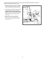
If you purchase the optional chest pulse sensor (see page 19), follow the steps below to install the re-
ceiver included with the chest pulse sensor.
1
. Make sure that the power cord is unplugged.
Remove the indicated 1/2" Screws (1) and the
A
ccess Door (87) from the Console Back (91).
2. Connect the wire on the receiver to the indicated
wire extending from the Console Back (91).
Hold the receiver so that the small cylinder is
oriented as shown and is facing the Console
Back. Attach the receiver to the plastic posts on
the Access Door (87) with the two included
small screws.
3. Make sure that no wires are pinched.
Reattach the Access Door (87) with the 1/2"
Screws (1). Discard the other wires included
with the receiver.
Receiver
87
Small
Cylinder
1
91
Wire
Small
Screws

OPERATION AND ADJUSTMENT
THE PRE-LUBRICATED WALKING BELT
Y
our treadmill features a walking belt coated with high-
performance lubricant. IMPORTANT: Never apply sil-
icone spray or other substances to the walking
belt or the walking platform. Such substances will
deteriorate the walking belt and cause excessive
wear.
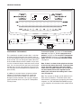
HOW TO PLUG IN THE POWER CORD
Your treadmill, like any other type of sophisticated
electronic equipment, can be seriously damaged by
sudden voltage changes in your homeʼs power.
Voltage surges, spikes, and noise interference can
result from weather conditions or from other appliances
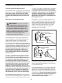
being turned on or off. To decrease the possibility of
your treadmill being damaged, always use a surge
suppressor with your treadmill (see drawing 1 at
the right). To purchase a surge suppressor, see
your local GOLDʼS GYM dealer or call the tele-
phone number on the front cover of this manual
and order part number 146148, or see your local
electronics store.
Use only a single-outlet surge suppressor that is
UL 1449 listed as a transient voltage surge sup-
pressor (TVSS). The surge suppressor must have a
UL suppressed voltage rating of 400 volts or less
and a minimum surge dissipation of 450 joules.
The surge suppressor must be electrically rated for
120 volts AC and 15 amps. There must be a moni-
toring light on the surge suppressor to indicate
whether it is functioning properly. Failure to use a
properly functioning surge suppressor could result
in damage to the control system of the treadmill. If
the control system is damaged, the walking belt
may change speed, accelerate, or stop unexpect-
edly, which may result in a fall and serious injury.
This product must be grounded. If it should malfunc-
tion or break down, grounding provides a path of least
resistance for electric current to reduce the risk of elec-
tric shock. This product is equipped with a cord having
an equipment-grounding conductor and a grounding
p
lug. Plug the power cord into a surge suppressor,
and plug the surge suppressor into an appropriate
outlet that is properly installed and grounded in
accordance with all local codes and ordinances.
IMPORTANT: The treadmill is not compatible with
GFCI-equipped outlets.
This product is for use on a nominal 120-volt circuit,
and has a grounding plug that looks like the plug illus-
trated in drawing 1 below. A temporary adapter that
looks like the adapter illustrated in drawing 2 may be
used to connect the surge suppressor to a 2-pole
receptacle as shown in drawing 2 if a properly
grounded outlet is not available.
The temporary adapter should be used only until a
properly grounded outlet (drawing 1) can be installed
by a qualified electrician.
The green-colored rigid ear, lug, or the like extending
from the adapter must be connected to a permanent
ground such as a properly grounded outlet box cover.
Whenever the adapter is used it must be held in place
by a metal screw. Some 2-pole receptacle outlet box
covers are not grounded. Contact a qualified elec-
trician to determine if the outlet box cover is
grounded before using an adapter.
DANGER: Improper connection
of the equipment-grounding conductor can
result in an increased risk of electric shock.
Check with a qualified electrician or service-
man if you are in doubt as to whether the
product is properly grounded. Do not modify
the plug provided with the product—if it will
not fit the outlet, have a proper outlet
installed by a qualified electrician.
1
2
Grounded Outlet Box
Grounded Outlet Box
Grounding Plug
Surge Suppressor
Surge Suppressor
Grounding Pin
Adapter
Lug
Metal Screw
Grounded Outlet
Grounding Pin
12

13
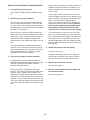
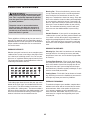
FEATURES OF THE CONSOLE
This revolutionary treadmill console offers a selection
of features designed to make your workouts more ef-
fective and enjoyable. When you use the manual mode
of the console, you can change the speed and incline
of the treadmill with the touch of a button. As you exer-
cise, the console will display continuous exercise feed-
back. You can even measure your heart rate using the
handgrip pulse sensor or the optional chest pulse sen-
sor (see page 19 for information on the optional chest
pulse sensor).
In addition, the console features 24 personal trainer
workouts. Each workout automatically controls the
speed and incline of the treadmill as it guides you
through an effective workout. You can even compete
against animated runners using the iFIT Competition
Training Center.
To turn on the power, see page 14. To use the man-
ual mode, see page 14. To use a personal trainer
workout, see page 16. To use the iFIT Competition
Training Center, see page 17. To use the settings
mode, see page 18. To use the information mode,
see page 19.
Note: If there is a sheet of clear plastic on the face
of the console, remove the plastic. To prevent dam-
age to the walking platform, wear clean athletic
shoes while using the treadmill. The first time you
use the treadmill, observe the alignment of the
walking belt, and center the walking belt if neces-
sary (see page 24).
Note: The console can display speed and distance in
either miles or kilometers. To find out which unit of
measurement is selected or to change the unit of mea-
surement, see THE INFORMATION MODE on page
19. For simplicity, all instructions in this section refer to
miles.
Clip
Key
CONSOLE DIAGRAM

14
HOW TO TURN ON THE POWER
IMPORTANT: If the treadmill has been exposed to
c
old temperatures, allow it to warm to room tem-
perature before turning on the power. If you do not
d
o this, the console displays or other electrical
components may become damaged.
Plug in the power cord
(see page 12). Next, lo-
cate the reset/off circuit
breaker on the treadmill
frame near the power
cord. Switch the circuit
breaker to the reset posi-
tion.
IMPORTANT: The console features a display demo
mode, designed to be used if the treadmill is dis-
played in a store. If the displays light as soon as
you plug in the power cord and switch the circuit
breaker to the reset position, the demo mode is
turned on. To turn off the demo mode, hold down
the Stop button for a few seconds. If the displays
remain lit, see THE INFORMATION MODE on page
19 to turn off the demo mode.
Next, stand on the foot rails of the treadmill. Find the
clip attached to the key (see the drawing on page 13)
and slide the clip onto the waistband of your clothes.
Then, insert the key into the console. After a moment,
the displays will light. IMPORTANT: In an emergency
situation, the key can be pulled from the console,
causing the walking belt to slow to a stop. Test the
clip by carefully taking a few steps backward; if the
key is not pulled from the console, adjust the posi-
tion of the clip.
HOW TO USE THE MANUAL MODE
1. Insert the key into the console.
See HOW TO TURN ON THE POWER to the left.
2. Select the manual mode.
Each time you insert the key, the manual mode will
be selected. If you have selected a workout, press
either of the workout buttons repeatedly until only
zeros appear in the display.
3. Start the walking belt and adjust the speed.
To start the walking belt, press the Start button, the
Speed increase button, or one of the Quick Speed
buttons numbered 1 to 12. Note: After you press
the buttons, it may take a moment for the walking
belt to reach the selected speed setting.
If you press the Start button or the Speed increase
button, the walking belt will begin to move at 1
mph. As you exercise, change the speed of the
walking belt as desired by pressing the Speed in-
crease and decrease buttons. Each time you press
a button, the speed setting will change by 0.1 mph;
if you hold down a button, the speed setting will
change in increments of 0.5 mph. If you press one
of the twelve numbered Quick Speed buttons, the
speed of the walking belt will gradually adjust until
it reaches the selected speed setting.
To stop the walking belt, press the Stop button. To
restart the walking belt, press the Start button, the
Speed increase button, or one of the numbered
Quick Speed buttons.
4. Change the incline of the treadmill as desired.
To change the incline of the treadmill, press the
Incline increase or decrease buttons, or one of the
Quick Incline buttons numbered 0 to 12. Each time
you press a button, the incline will gradually adjust
until it reaches the selected incline setting.
Reset
Position

15
5. Follow your progress with the display.
The console offers several display options. The dis-
p
lay option you select will determine which workout
information is shown. Press the Display button re-
p
eatedly to select the desired display option.
As you walk or run on the treadmill, the display can
show the following workout information:
• The elapsed time.
• The distance you have walked or run.
• The approximate number of calories you have
burned.
• The approximate number of calories burned per
hour.
• Your exercise intensity in METs. One MET is the
amount of energy you use while resting.
• The speed of the walking belt.
• The incline level of the treadmill.
• Your pace in minutes per mile or minutes per kilo-
meter.
• Your heart rate.
Note: Regardless of which display mode you select,
the speed or incline setting will appear in the dis-
play for a few seconds each time you change the
setting. In addition, your heart rate will appear in the
display each time you use the handgrip pulse sen-
sor or the optional chest pulse sensor (see step 6).
6. Measure your heart rate if desired.
You can measure your heart rate using either the
handgrip pulse sensor or the optional chest pulse
sensor (see page 19 for information about the op-
tional chest pulse sensor). Note: If you hold the
handgrip pulse sensor and wear the optional chest
p
ulse sensor at the same time, the console will not
display your heart rate accurately.
Before using the handgrip pulse sensor, remove
the sheets of clear plastic from the metal contacts.
In addition, make sure that your hands are clean.
To measure
your heart rate,
stand on the
foot rails and
hold the metal
contacts on the
handrail—
avoid moving
your hands.
When your
pulse is detected, your heart rate will be shown.
For the most accurate heart rate reading, con-
tinue to hold the contacts for about 15 sec-
onds.
7. When you are finished exercising, remove the
key from the console.
Step onto the foot rails, press the Stop button, and
adjust the incline of the treadmill to the lowest
setting. The incline must be at the lowest setting
when you fold the treadmill to the storage posi-
tion or you may damage the treadmill. Next, re-
move the key from the console and put it in a secure
place.
When you are finished using the treadmill, switch
the reset/off circuit breaker to the “off” position and
unplug the power cord. Important: If you do not
do this, the electrical components of the tread-
mill may wear prematurely.
Contacts

16
HOW TO USE A PERSONAL TRAINER WORKOUT
1. Insert the key into the console.
See HOW TO TURN ON THE POWER on page
1
4.
2. Select a personal trainer workout.
To select one of the 24 personal trainer workouts,
press the Select Workout button. Then press the
Increase and Decrease buttons below the Select
Workout button until the name of the desired work-
out appears in the display.
When you select a personal trainer workout, the
display will show the name, the duration, the maxi-
mum incline setting, and the maximum speed set-
ting of the workout. In addition, a profile of the
speed settings of the workout will appear in the dis-
play.
Each preset workout is divided into one-minute
segments. One speed setting and one incline set-
ting are programmed for each segment. Note: The
same speed and/or incline setting may be pro-
grammed for consecutive segments.
3. Press the Start button to start the workout.
A moment after you press the Start button, the
treadmill will automatically adjust to the first speed
and incline settings of the workout. Hold the
handrails and begin walking.
During the program, the profile will show your
progress. The flashing segment of the profile repre-
sents the current segment of the program. The
height of the flashing segment indicates the speed
setting for the current segment. At the end of each
segment, a series of tones will sound, the next seg-
ment of the profile will begin to flash and the speed
and incline setting will appear in the display to alert
you.
The program will continue in this way until the last
segment of the profile flashes in the display and
the last segment ends. The walking belt will then
s
low to a stop.
I
f the speed or incline setting for the current seg-
ment is too high or too low, you can manually over-
ride the setting by pressing the Speed and Incline
buttons. Every few times a Speed button is
pressed, an additional indicator will appear or dis-
appear in the current segment column. However,
when the next segment of the program begins,
the treadmill will automatically adjust to the
speed and incline settings for the next segment.
To stop the program at any time, press the Stop
button. To restart the program, press the Start but-
ton or the Speed increase button. The walking belt
will begin to move at 1 mph. When the next seg-
ment of the program begins, the treadmill will auto-
matically adjust to the speed and incline settings for
that segment.
4. Follow your progress with the display.
See step 5 on page 15.
Instead of showing elapsed time, the display will
show the time remaining in the workout. The dis-
play will also show your energy output in watts.
5. Measure your heart rate if desired.
See step 6 on page 15.
6. When you are finished exercising, remove the
key from the console.
See step 7 on page 15.

17
HOW TO USE THE IFIT COMPETITION TRAINING
CENTER
1
. Insert the key into the console.
S
ee HOW TO TURN ON THE POWER on page
14.
2. Select the iFIT Competition Training Center.
To select the iFIT Competition Training Center,
press the Select Event button. Use the Increase
and Decrease buttons below the Select Event to
select a race against a group of four opponents or
against one opponent.
If you choose to compete against a group, highlight
the RACE AGAINST A PACK option and then
press the Enter button below the Select Event but-
ton. Select a level of difficulty and the distance of
the race by pressing the Increase and Decrease
buttons. Press the Enter button after each selec-
tion.
If you choose to race against one opponent, high-
light the RACE A SINGLE OPPONENT option and
then press the Enter button. Press the Increase
and Decrease buttons to select an opponent and
the distance of the race. Press the Enter button
after each selection. Note: Each opponent appears
more than once with different levels of difficulty, or
tiers.
A few moments after you select the length of the
race, the race will begin. Hold the handrails and
begin walking. Adjust the speed and incline of the
treadmill as desired.
The workout will continue until the race ends.
3. Follow your progress with the display.
The console offers several display options. The dis-
play option you select will determine which workout
information is shown. Press the Display button re-
peatedly to select the desired display option.
A
s you walk or run on the treadmill, the display can
show the following workout information:
• An animation of a runner labeled “U,” which rep-
resents you. As you increase or decrease the
speed of the walking belt, the runner will speed
up or slow down.
• Animations of the other runners.
• A map of the course you are running will appear
on the left side of the screen. The runners will be
represented by squares on the map.
• Your number of seconds ahead of the other run-
ners or behind the lead runner will appear below
the map of the course. If you are behind the other
runners, a negative number of seconds will ap-
pear.
• Your rank in the race will appear inside the map
of the course.
• The speed of the walking belt. Note: Press the
Enter button to see your pace in minutes per kilo-
meter or minutes per mile. Press the Enter button
again to view the speed of the walking belt.
• The incline level of the treadmill.
• The approximate number of calories you have
burned.
• The distance that you have walked or run.
• The elapsed time.
• Your heart rate. Note: Your heart rate can be dis-
played only while you use the handgrip pulse sen-
sor or the optional chest pulse sensor (see page
15).

18
• A profile of the incline settings of the race will ap-
pear in the lower part of the screen.
•
A status bar showing the distance you have trav-
elled in the race and the distance you still have to
t
ravel.
• Your average speed.
• The rate at which your opponents recover their
energy (rec). Your row in the rec column will dis-
play the approximate number of calories you have
burned.
• The bank, or amount, of energy your opponents
have left. As the amount of energy in a bank de-
creases, the speed of that opponent will de-
crease.
• The racing tactics your opponents are using. Your
opponents will use different tactics in different situ-
ations. Consult a reputable source to learn more
about these tactics.
4. Measure your heart rate if desired.
See step 6 on page 15.
To view your heart rate, select the display option
which shows the animation of the runners.
5. When you are finished exercising, remove the
key from the console.
See step 7 on page 15.
HOW TO USE THE SETTINGS MODE
1. Insert the key into the console.
See HOW TO TURN ON THE POWER on page
1
4.
2. Select the settings mode.
To select the settings mode, press the Select
Event button. Highlight the SETTINGS option and
press the Enter button. The menu will show the
maximum incline of the race, the incline selection
setting, and the start speed for the race.
3. Enter user information.
Press the Increase and Decrease buttons until an
arrow appears next to the desired option. Then,
press the Enter button. A flashing cursor will ap-
pear in the field in the display. Press the Increase
and Decrease buttons to change the selection.
When you have finished changing the field, press
the Enter button. Repeat this action to enter all the
desired information.
When you are done changing the settings, highlight the
EXIT SETTINGS option and press the Enter button.

19
THE INFORMATION MODE
The console features an information mode that allows
y
ou to select a unit of measurement for the console,
turn on or turn off the display demo mode, and change
t
he contrast of the display.
To select the information mode, hold down the Stop
button, insert the key into the console, and then release
the Stop button. When the information mode is se-
lected, the following information will appear in the dis-
play:
The display will show the selected unit of measure-
ment. To change the unit of measurement, press the
Speed increase button. To view distance in miles, se-
lect ENGLISH. To view distance in kilometers, select
METRIC.
The console features a display demo mode, designed
to be used if the treadmill is displayed in a store. While
the demo mode is turned on, the console will function
normally when you plug in the power cord, switch the
reset/off circuit breaker to the reset position, and insert
the key into the console. However, when you remove
the key, the displays will remain lit, although the but-
tons will not function. If the demo mode is turned on,
the word “ON” will appear in display while the informa-
tion mode is selected. To turn on or turn off the demo
mode, press the Speed decrease button.
To adjust the contrast of the display, press the Incline in-
crease and decrease buttons.
To exit the information mode, remove the key from the
console.
THE OPTIONAL CHEST PULSE SENSOR
An optional chest pulse sensor offers hands-free oper-
a
tion as it tracks your heart rate during your workouts.
To purchase the optional chest pulse sensor, call
t
he telephone number on the front cover of this
manual.
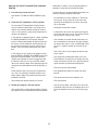
HOW TO ADJUST THE CUSHIONING SYSTEM
Remove the key from the console and unplug the
power cord. The treadmill features a cushioning sys-
tem that reduces the impact as you walk or run on the
treadmill. To increase the firmness of the walking plat-
form, step off the treadmill and slide the platform cush-
ions toward the front of the treadmill. To decrease the
firmness, step off the treadmill and slide the platform
cushions toward the back of the treadmill. Note: Make
sure that both cushions are set at the same firm-
ness level. The faster you run on the treadmill, or
the more you weigh, the firmer the walking plat-
form should be.
Platform
Cushion
Walking Platform
Increase
Decrease
Platform
Cushion

20
HOW TO FOLD AND MOVE THE TREADMILL
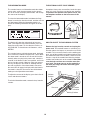
HOW TO FOLD THE TREADMILL FOR STORAGE
Before folding the treadmill, adjust the incline to the
l
owest position. If you do not do this, you may damage the
treadmill when you fold it. Remove the key and unplug the
power cord. CAUTION: You must be able to safely lift 45
lbs. (20 kg) to raise, lower, or move the treadmill.
1. Hold the metal frame firmly in the location shown by
the arrow at the right. CAUTION: To decrease the pos-
sibility of injury, do not lift the frame by the plastic
foot rails. Make sure to bend your legs and keep your
back straight as you raise the frame. Raise the frame
about halfway to the vertical position.
2. Raise the frame until the latch knob locks into the storage
position. Make sure that the latch knob is locked in
the storage position.
To protect the floor or carpet from damage, place a
mat under the treadmill. Keep the treadmill out of di-
rect sunlight. Do not leave the treadmill in the stor-
age position in temperatures above 85° F (30° C).
HOW TO MOVE THE TREADMILL
Before moving the treadmill, convert the treadmill to the stor-
age position as described above. Make sure that the latch
knob is locked in the storage position.
1. Hold a handrail and the frame and place one foot against
one of the wheels.
2. Tilt the treadmill back until it rolls freely on the wheels.
Carefully move the treadmill to the desired location. Never
move the treadmill without tipping it back. To reduce
the risk of injury, use extreme caution while moving
the treadmill. Do not attempt to move the treadmill
over an uneven surface.
3. Place one foot against a wheel, and carefully lower the
treadmill until it is resting in the storage position.
Handrail
Frame
Wheel
Latch Knob
Frame
Page is loading ...
Page is loading ...
Page is loading ...
Page is loading ...
Page is loading ...
Page is loading ...
Page is loading ...
Page is loading ...
Page is loading ...
Page is loading ...
Page is loading ...
Page is loading ...
-
 1
1
-
 2
2
-
 3
3
-
 4
4
-
 5
5
-
 6
6
-
 7
7
-
 8
8
-
 9
9
-
 10
10
-
 11
11
-
 12
12
-
 13
13
-
 14
14
-
 15
15
-
 16
16
-
 17
17
-
 18
18
-
 19
19
-
 20
20
-
 21
21
-
 22
22
-
 23
23
-
 24
24
-
 25
25
-
 26
26
-
 27
27
-
 28
28
-
 29
29
-
 30
30
-
 31
31
-
 32
32


Gold's Gym 705 ZLT . PETL79810.0 User manual
- Category
- Treadmills
- Type
- User manual
- This manual is also suitable for
Ask a question and I''ll find the answer in the document
Finding information in a document is now easier with AI
Related papers
-
Gold's Gym Crosswalk 570 User manual
-
-
-
Pro-Form Cadence Af 5.1 Treadmill User manual
-
-
-
-
-
-
Other documents
-
ProForm 831.24745.2 User manual
-
-
-
-
-
-
-
-
-