Page is loading ...

Johnson Controls Ducted Systems 5407934-UIM-C-1119
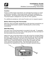
Hx™3 TOUCH SCREEN THERMOSTAT
MODELS: S1-THXU430W
INSTALLATION MANUAL
11/07/18 11:14AM
º
72
Auto
COOL TO
85
62
Settings
11/07/18 11:14AM
.
LIST OF SECTIONS
GENERAL . . . . . . . . . . . . . . . . 2
SAFETY CONSIDERATIONS . 2
INSPECTION . . . . . . . . . . . . . . . . 3
LIMITATIONS . . . . . . . . . . . . . . . 3
CONVENTIONAL
COMPATIBILITY CHECK . . . . . . 3
COMMUNICATING
SYSTEM INSTALLATION . . . . 4
LOCATION . . . . . . . . . . . . . . . . . 5
MOUNTING
THE THERMOSTAT . . . . . . . . . . 5
INSTALLING A
NEW THERMOSTAT . . . . . . . . . 6
WIRING COMMUNICATION . . 8
WIRING REQUIREMENTS . . . . . 8
SYSTEM WIRING OVERVIEW . . 8
HUMIDIFIER CONNECTION . . 25
HUMIDIFICATION AND
DEHUMIDIFICATION . . . . . . . 28
INITIAL POWER-UP . . . . . . . .30
POWER-UP . . . . . . . . . . . . . . . 31
SYSTEM CONFIGURATION . . 31
SOFTWARE UPDATES . . . . . . 36
SERVICE MODE . . . . . . . . . . .37
ACCESSING SYSTEM
SETTINGS . . . . . . . . . . . . . . . . 37
SYSTEM SETTINGS . . . . . . . . 38
FAULTS AND
SYSTEM EVENTS . . . . . . . . . . 47
AIRFLOW CONFIGURATION . . 64
FORCED OPERATION . . . . . . . 65
VENTILATION SETTINGS . . . . 67
RESTORE DEFAULTS . . . . . . . 68
SERVICE SETTINGS . . . . . . .70
LOG . . . . . . . . . . . . . . . . . . . . . . 70
DEALER INFORMATION . . . . . 71
STATUS . . . . . . . . . . . . . . . . . . 73
WIRING DIAGRAMS . . . . . . . .74

5407934-UIM-C-1119
2 Johnson Controls Ducted Systems
SECTION I: GENERAL
The Hx™3 Touch Screen Thermostat is designed to control conven-
tional and communicating HVAC systems. Use applicable Johnson Con-
trols Ducted Systems communicating equipment as follows:
• Variable speed modulating furnace
• Two-stage variable speed ECM furnace
• Variable speed air handler
• Premium 19 and 21 SEER air conditioners
• Premium 19 and 20 SEER heat pumps
• Variable capacity systems
While the communicating system has been designed for easy installa-
tion, this document provides a more detailed explanation of the installa-
tion process for installers. For communicating zoning applications,
please refer to the literature kit that is included with the Zone Module
(S1-ZMC401A).
To use the complete feature set available, you must connect the Hx™3
Touch Screen Thermostat to Wi-Fi.
For ease of installation and to ensure the thermostat has the latest soft-
ware updates, make sure that Wi-Fi access is available (through the
homeowner’s Wi-Fi network or a mobile hotspot).
SECTION II: SAFETY CONSIDERATIONS
This is a safety alert symbol. When you see this symbol on labels
or in manuals, be alert to the potential for personal injury and equipment
damage.
Understand and pay particular attention to the signal words DANGER,
WARNING, and CAUTION.
DANGER indicates an imminently hazardous situation, which, if not
avoided,
will result in death or serious injury.
WARNING indicates a potentially hazardous situation, which, if not
avoided,
could result in death or serious injury.
CAUTION indicates a potentially hazardous situation, which, if not
avoided
may result in minor or moderate injury. It is also used to alert
against unsafe practices and hazards involving only property damage.

5407934-UIM-C-1119
Johnson Controls Ducted Systems 3
INSPECTION
The following table details the parts included in this kit. Examine the kit
to ensure all parts are present.
LIMITATIONS
The primary function of the thermostat is to command a system contain-
ing communicating products.
The following are exceptions:
• Installing a communicating variable speed modulating furnace with
a non-communicating air conditioner. In this case, the variable-
speed modulating furnace relays 24 VAC outputs to the non-com-
municating air conditioner (per communicated commands by the
thermostat).
• Installing communicating controls in non-communicating Ducted
Systems products
• Installing a communicating interface control (which converts com-
municating commands into 24 VAC outputs)
CONVENTIONAL COMPATIBILITY CHECK
The Hx™3 Touch Screen Thermostat works with 24 VAC systems and
requires both R and C 24 VAC connections. This includes gas furnaces,
air handlers, electric, oil, forced air, variable speed, heat pump, and
hydronic heat.
TABLE 1:
Content List
Item QTY Description
1 1 Thermostat Display
2 1 Thermostat Base
4 2 Screws
5 2 Drywall Anchors
6 1 User’s Information Manual
7 1 Installation Manual

5407934-UIM-C-1119
4 Johnson Controls Ducted Systems
You can configure the thermostat for the following:
• Conventional up to 2H/2C and heat pump up to 4H/2C
• Heating: 1 and 2 stages (W1, W2)
• Cooling: 1 and 2 stages (Y1, Y2)
• Heat pump: With auxiliary and emergency heat or fossil fuel
• HUM, O/B, Y2, Y1, W1, W2
• Fan single speed (G)
• Power (R, C) dual fuel compatible (heat pump with gas furnace)
• Humidity control (humidify and dehumidify)
• Outdoor air temperature or remote room sensor (optional)
SECTION III: COMMUNICATING SYSTEM
INSTALLATION
The intention of this document is to ensure proper connection and setup
of the various communicating system components. Use these instruc-
tions in conjunction with instructions provided with indoor, outdoor, and
accessory equipment with which the thermostat is used.
This manual contains information about setup, operation, and trouble-
shooting. Short videos illustrating the installation, setup, and configura-
tion of the Hx™3 Touch Screen Thermostat are available at
www.simplygettingthejobdone.com in the Academy TV application.
Installers must be trained, experienced service technicians. When
installing this product, do the following:
• Read all instructions carefully before beginning the installation.
• Make sure the product is suitable for your application by checking
all ratings on the product and in the instructions provided.
NOTICE
Dual fuel systems require the use of the ambient sensor (S1-
02542683000), if the room thermostat is used to control fossil fuel
operation.
WARNING
Failure to follow these instructions can create hazardous situations or
damage the product.
!

5407934-UIM-C-1119
Johnson Controls Ducted Systems 5
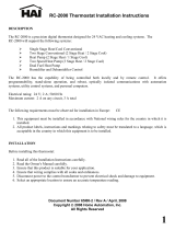
LOCATION
Install the thermostat at or around 5 ft (1.5 m) above the floor in an area
with good circulation of room temperature. See Figure 1.
Do not install the thermostat where it can be affected by the following:
• Drafts or stagnant air behind doors and in corners
• Hot or cold air from ducts
• Radiant heat from sun or appliances
• Concealed pipes and chimneys
• Unconditioned areas, such as an outside wall
MOUNTING THE THERMOSTAT
For most installations, you (the installer) can mount the thermostat by
following the basic installation steps outlined below. However, there may
be some cases where you are not able to penetrate the wall where you
are mounting the thermostat, or where the thermostat being replaced
has left a larger hole than needed for installation. For these and other
cases (including installation with a vertical junction box), you can obtain
an accessory wall plate.
FIGURE 1: Control Location
12
12
12
<(6
)((7
0(7(56
$

5407934-UIM-C-1119
6 Johnson Controls Ducted Systems
Follow these steps:
1. Turn off all power to the indoor and outdoor equipment.
2. If an existing thermostat is being replaced:
a. Disconnect the wires from the existing thermostat.
b. Remove the existing thermostat from the wall.
c. Properly discard or recycle the old thermostat.
3. Mark where the thermostat is to be mounted on the wall (standard
height is 5 ft from the floor).
INSTALLING A NEW THERMOSTAT
1. Position the thermostat base against the wall and determine if it com-
pletely covers the footprint of the current thermostat.
2. Position the thermostat base against the wall (or wall plate if used)
and determine if the new screw locations align with prior locations.
3. If the thermostat base does not align with the existing anchor holes,
mark the new screw locations with a pencil.
• Drywall: Drill a 3/16 in. hole for the anchor and install.
• Plaster: Drill a 7/32 in. hole for the anchor and install.
4. If the remote sensor is to be used, pull the wires through and connect
them to the S1 and S2 terminals. Use the ambient sensor (S1-
02542683000), which you can purchase separately.
WARNING
Voltage Hazard: Live wires can cause electrical shock or equipment
damage. Disconnect power before beginning installation.
NOTICE
Mercury is a hazardous substance. If the existing thermostat contains
any mercury, it MUST be disposed of properly. This thermostat does
not contain mercury.
NOTICE
If a thermostat was formerly in place, evaluate the location to make
sure it meets the location requirements outlined earlier in this docu-
ment.
!

5407934-UIM-C-1119
Johnson Controls Ducted Systems 7
5. Pull the wires through the opening in the thermostat base and secure
the thermostat base (and wall plate) to the wall using the screws pro-
vided.
6. Though not required for operation, it is best practice that the thermo-
stat is level.
7. One by one, connect each wire by pushing down on the quick con-
nect tab, inserting the wire into the connector opening, and releasing
the tab to complete.
8. Ensure the thermostat base is positioned with the UP arrow pointing
upwards. See Figure 2.
9. Align the four positioning tabs with the four slots on the back side of
the screen and gently press the screen into place.
10.Fasten the screen to the thermostat base with the two retaining
screws provided.
The thermostat may be wired conventionally. For wiring diagrams,
see Section IX: Wiring Diagrams.
FIGURE 2: Thermostat Installation and Components
UP ARROW
RETAINING SCREWS x2
BASE
SCREEN
POSITIONING
TABS
(Note orientation)
QUICK
CONNECT
TABS
A0972-001

5407934-UIM-C-1119
8 Johnson Controls Ducted Systems
SECTION IV: WIRING COMMUNICATION
All wiring must comply with local electrical codes and ordinances. See
Table 2 for terminal designations.
WIRING REQUIREMENTS
Use standard 18 AWG thermostat wires to connect the communicating
HVAC system and the conventional HVAC system.
Special (shielded) cable is not typically required. As with all communicat-
ing devices, it is a good idea to keep wiring at least 1 ft away from large
inductive loads, for example, electronic air cleaners and motors. If these
wiring practices are ignored, it may introduce electrical interference
(noise), which can cause erratic system operation.
SYSTEM WIRING OVERVIEW
WARNING
If using the thermostat with variable capacity outdoor equipment, DO
NOT connect to the R terminal of the outdoor unit control board.
TABLE 2:
Terminal Designations
Signal Definition Label
Data Non-inverted signal A (+)
Low-voltage power hot 24 VAC (Hot) R
Low-voltage power common and data ground 24 VAC (Common) C
Data Inverted signal B (-)
NOTICE
There may be installation applications where large inductive loads
cannot be avoided. In these cases, use shielded wire in proximity to
the inductive loads to ensure proper system functionality.
IMPORTANT: The communicating system requires four wires to oper-
ate. If installing a communicating system, ensure to supply at least
four wires to each unit/control. For a simple diagram of the ideal wiring
path, see Figure 3.
!

5407934-UIM-C-1119
Johnson Controls Ducted Systems 9
The system is connected by four wires. Two of the wires are used to
bring power to the individual controls (R and C), and two of the wires are
used for serial communication (A+ and B-).
Variable capacity outdoor units only require three wires. Variable capac-
ity equipment has its own transformer, so it does not require an R con-
nection between the indoor and outdoor equipment.
FIGURE 3: High-Level Wiring Path
FIGURE 4: Wiring Diagram - Fully Communicating System Components
Z
KDD͘KDD͘
$*5((1:,5(
55(':,5(
&%/$&.:,5(
%%/8(:+,7(:,5(
$5&%
$5&%
$5&%
287'22581,7
,1'22581,7
$
'2127
FRQQHFWWR
YDULDEOHFDSDFLW\
RXWGRRUHTXLSPHQW
Touch Screen
Communicating
Control
VS Air Handler/Furnace
Communicating
Control
Air Conditioner/Heat Pump
Communicating
Control
A+
R
GND
B-
A+
R
C
B-
A+
R
C
B-
A0611-002
DO NOT connect to variable capacity outdoor equipment.

5407934-UIM-C-1119
10 Johnson Controls Ducted Systems
FIGURE 5: Wiring Diagram - Variable Capacity System
FIGURE 6: Wiring Diagram - Modulating Communicating Furnace,
Non-Communicating AC
Air Handler / Furnace
Communicating Control
Variable Capacity
AC / Heat Pump
Communicating
Control
Hx3
Thermostat
Indoor EEV
A0826-003
C
B -
R
A +
C
B -
R
A +
C
B -
R
A +
A +
R
B -
C C
B -
R
A +
A+
R
C
B-
A+
R
GND
B-
LO
COMP
HI
COMP
O
DHUM
Y1
Y/Y2
W
R
G
C
Y
Y2
R
C
Modulating Furnace
Communicating Control
Non-Communicating
Air Conditioner
A0612-004
Hx3 Thermostat

5407934-UIM-C-1119
Johnson Controls Ducted Systems 11
Thermostat Wiring
1. Turn off all power to the equipment.
2. Remove the thermostat front plate.
3. Match and connect the thermostat wires to the proper terminals on
the thermostat mounting back plate.
4. Push any excess wiring back into the wall.
Outdoor Control Wiring
Figure 7 shows a communicating AC control (see top of figure) and a
communicating heat pump control (see bottom of figure). The communi-
cating terminals shown are in parallel. Connect to either terminal.
WARNING
ELECTRICAL OPERATION HAZARD
Failure to follow this warning could result in personal injury, death, or
equipment damage. Before installing, modifying, or servicing the sys-
tem, the main electrical disconnect switch must be in the OFF posi-
tion. There may be more than one disconnect switch. Lock out and tag
each switch with a suitable warning label.
NOTICE
Plugging the hole in the wall with nonflammable insulation can help
prevent drafts from adversely affecting temperature control.
!

5407934-UIM-C-1119
12 Johnson Controls Ducted Systems
FIGURE 7: Communicating Outdoor Controls - AC and Heat Pump
&20081,&$7,1*7(50,1$/6
&20081,&$7,1*7(50,1$/6
&20081,&$7,1*$&&21752/
&20081,&$7,1*+($73803&21752/
$

5407934-UIM-C-1119
Johnson Controls Ducted Systems 13
FIGURE 8: Variable Capacity Equipment - AC/Heat Pump Control
FIGURE 9: 2-Stage AC/Heat Pump Control
COMMUNICATING
TERMINALS
A0827-002
DO NOT connect indoor equipment "R" connection to this terminal.
COMMUNICATING TERMINALS
A0951-001

5407934-UIM-C-1119
14 Johnson Controls Ducted Systems
Communicating Non-Variable Capacity Models
Figures 3 and 4 show control wiring using communicating controls (non-
variable capacity legacy outdoor models).
Using a Communicating Wiring Harness
To use the S1-02542694000 communicating wiring harness:
1. Disconnect all high-voltage power from the system.
2. Plug the S1-02542694000 communicating harness into the outdoor
control board and route the harness to the low-voltage wiring com-
partment.
3. Remove the conventional low-voltage wiring leads from the outdoor
control board. Leave the wiring leads with the outdoor unit for future
use.
4. Connect the field low-voltage thermostat wiring to the communicating
control harness using spring wire connectors (commonly referred to
as wire nuts).
5. Push excess wiring into the low-voltage wiring compartment of the
outdoor unit.
6. Set the wires that are now connected (with wire connectors) into the
junction box of the control housing.
7. Set the appropriate outdoor jumper settings to ensure proper control
functionality. See Table 3.
WARNING
ELECTRICAL OPERATION HAZARD
Failure to follow this warning could result in personal injury, death, or
equipment damage. Before installing, modifying, or servicing the sys-
tem, the main electrical disconnect switch must be in the OFF posi-
tion. There may be more than one disconnect switch. Lock out and tag
each switch with a suitable warning label.
IMPORTANT: This procedure is only applicable to legacy communi-
cating systems as follows: CZF, CZH, AC6B, AC8B, AL6B, AL8B,
YZF, YZH, HC6B, HC8B, HL6B, and HL8B.
NOTICE
When connecting the loose ends of the wire harness, ensure to note
the color of each of the four wires (A+, R, C, B-).
!

5407934-UIM-C-1119
Johnson Controls Ducted Systems 15
Control Wiring Using Communicating Controls: Non-Vari-
able Capacity Outdoor Models
1. Disconnect all high-voltage power from the system.
2. The outdoor unit contains a wire harness for conventional wiring and
a wire harness for communicating wiring. Locate the wire harness
with the plastic plug on the end. Cut the plastic connector off of the
wire harness to be used and strip the wires approximately 1/2 in.
3. Connect the field low-voltage thermostat wiring to the appropriate
harness using spring wire connectors.
4. Push excess wiring into the low-voltage wiring compartment of the
outdoor unit.
5. Set the appropriate outdoor jumper settings to ensure proper control
functionality. See Table 3.
Control Wiring Using Communicating Controls: Variable
Capacity Outdoor Models
1. Disconnect all high-voltage power from the system.
2. The outdoor unit contains a wire harness for communicating wiring. A
plastic connector used in manufacturing is left on the end of the con-
trol wires. Cut the plastic connector off of the wire harness and strip
the wires approximately 1/2 in.
3. Connect the field low-voltage thermostat wiring to the harness using
spring wire connectors. DO NOT connect the R connection of the
indoor equipment to the outdoor control board.
4. Push excess wiring into the low-voltage wiring compartment of the
outdoor unit.

5407934-UIM-C-1119
16 Johnson Controls Ducted Systems
FIGURE 10: Variable Capacity - Outdoor Control Housing
COMMUNICATIONS PORT
COMMUNICATIONS HARNESS
(shown through control box and low voltage shield)
OUTDOOR DISPLAY
CONTROL BOARD
A0614-003
DO NOT connect field low voltage
thermostat wiring to this connection.
Use the supplied wiring harness.
PLASTIC CONNECTOR
(cut off plastic connector to connect
thermostat wiring)

5407934-UIM-C-1119
Johnson Controls Ducted Systems 17
FIGURE 11: 2-Stage AC/Heat Pump - Outdoor Control Housing
TABLE 3:
Outdoor Jumper Settings
Unit Control Jumpers That Must Be Set
Heat Pump
Fossil Fuel: Set this jumper to ON if
using a gas furnace.
Air Conditioner No jumpers to set
Variable Capacity AC/HP No jumpers to set
COMMUNICATIONS PORT
COMMUNICATIONS HARNESS
(SHOWN THROUGH CONTROL BOX)
CONTROL BOARD
A0950-001

5407934-UIM-C-1119
18 Johnson Controls Ducted Systems
Variable Capacity Models
1. Disconnect all high-voltage power from the system.
2. Locate the factory-installed low-voltage wire harness at the bottom of
the control box.
3. Connect the three low-voltage wires using wire connectors. See Fig-
ure 12 for the wiring diagram.
WARNING
DO NOT connect the R terminal from the thermostat to the unit control
board.
!

5407934-UIM-C-1119
Johnson Controls Ducted Systems 19
FIGURE 12: Typical Communicating Field Wiring - Variable Capacity
Outdoor Unit
32:(5:,5,1*
&21752/:,5,1*
)$&725<:,5,1*
%
5
$
&
$
$//),(/':,5,1*72%(,1$&&25'$1&(:,7+(/(&75,&&2'(1(&$1'25/2&$/
7(50,1$/
%/2&.
&21752/
%2$5'
*1'
/8*
)851$&(25$,5+$1'/(5
7(50,1$/%/2&.
+[7+(50267$7
287'22581,7
$//287'225:,5,1*0867%(:($7+(53522)
86(&233(5&21'8&725621/<
32:(5:,5,1*
92/7&21752/:,5,1*
0,1,080*$:,5(
1(&&/$66
&
$
%
%
5
$&
'2127FRQQHFWWKH³5´WHUPLQDOIURP
WKHWKHUPRVWDWWRWKHXQLWFRQWUROERDUG
:+7
*51
%/.

5407934-UIM-C-1119
20 Johnson Controls Ducted Systems
Indoor Control Wiring
IMPORTANT: DO NOT place more than one wire under any single
communication terminal screw (there are four communication terminal
screws). If more than one wire must be connected to a terminal screw,
attach only the terminal end of a one-wire pigtail no longer than 6 in.,
and use a wire connector to connect the other end of the pigtail to the
other wires. Failure to do this results in nuisance communication error
faults. See Figure 13.
FIGURE 13: Multi-Wire Terminal Connection
FIGURE 14: Communicating Indoor Controls - Air Handler
:,5(
&211(&725
7+(50267$7
7(50,1$/
6&5(:
127(
(QVXUHRQO\RQHZLUHXQGHU
WHUPLQDOVFUHZ
7RFRQQHFWPRUHWKDQRQHZLUH
$
5
&
%
$,5+$1'/(5
&20081,&$7,1*
&21752/%2$5'
&RQQHFWRQO\WHUPLQDOHQGRI
´ZLUHSLJWDLO
8VHZLUHFRQQHFWRUWRFRQQHFW
RWKHUHQGRISLJWDLO
WRRWKHUZLUHV
$
287'22581,7
,1'22581,7
COMMUNICATING TERMINALS
COMMUNICATING
(AHV/AVC/MVC/AVV) CONTROL
A0615-002
/