Eaton Crouse-hinds series Operating Instructions Manual

Type
Operating Instructions Manual

This manual is also suitable for

Steckvorrichtungen für Industrieanwendungen
32 A, 3-polig, 4-polig, 5-polig, GHG 522
Plug and socket system for industrial use
32 A, 3-pole, 4-pole, 5-pole, GHG 522
Fiches et prises de 32 A, à 3 pôles, 4 pôles, 5 pôles,
pour utilisation industrielle, GHG 522
Betriebsanleitung
Operating instructions
Mode d’emploi
CROUSE-HINDS
SERI ES
GHG 510 7002 P0003 D/GB/F (h)
2
Steckvorrichtung 32 A,
GHG 522
Plug and socket system 32 A,
GHG 522
Fiches et prises de 32 A,
GHG 522
Inhalt:
Inhalt ....................................................... 2
Maßbild ................................................ 3-4
1 Technische Angaben ............................... 3
1.1 Steckvorrichtung GHG 522 ..................... 3
2 Sicherheitshinweise ................................ 4
3 Normenkonformität ................................. 4
4 Verwendungsbereich .............................. 4
5 Verwendung / Eigenschaften ............... 4-5
6 Installation ............................................... 5
6.1 Montage .................................................. 5
6.2 Öffnen des Gerätes /
Elektrischer Anschluss ............................ 5
6.3 Kabel- und Leitungseinführung;
Verschlussstopfen ................................... 6
6.4 Schließen des Gerätes ............................ 6
6.5 Inbetriebnahme ....................................... 6
7 Instandhaltung/Wartung .......................... 6
8 Reparatur / Instandsetzung /
Änderungen ............................................ 6
9 Entsorgung / Wiederverwertung ............. 6
Konformitätserklärung separat beigelegt.
Contents:
Contents ................................................. 2
Dimensional drawings ...........................7-8
1 Technical data .......................................... 7
1.1 Plug and socket GHG 522 ....................... 7
2 Safety instructions .................................. 8
3 Conformity with standards ...................... 8
4 Field of application .................................. 8
5 Application/Properties .......................... 8-9
6 Installation ............................................... 9
6.1 Mounting ................................................. 9
6.2 Opening the device /
Electrical connection ............................... 9
6.3 Cable entry (KLE); blanking plug ............10
6.4 Closing the device ..................................10
6.5 Taking into operation ..............................10
7 Maintenance/Servicing...........................10
8 Repairs / Modifications ..........................10
9 Disposal / Recycling ...............................10
Declaration of conformity, enclosed separately.
Contenu:
Contenu .................................................. 2
Plans cotés ........................................ 11-12
1 Caractéristiques techniques ..................11
1.1 Fiche et prise GHG 522 ..........................11
2 Consignes de sécurité ...........................12
3 Conformité avec les normes ..................12
4 Domaine d’utilisation .............................12
5 Utilisation / Propriétés ....................... 12-13
6 Installation ..............................................13
6.1 Montage .................................................13
6.2 Ouverture de l’appareil/
Raccordement électrique .......................13
6.3 Entrées de câble (KLE)
bouchons de fermeture .........................14
6.4 Fermeture de l’appareil/
Fermeture du couvercle .........................14
6.5 Mise en service ......................................14
7 Maintien / Entretien ...............................14
8 Réparation / Remise en état /
Modifications .........................................14
9 Évacuation des déchets /
Recyclage ............................................... 14
Déclaration de conformité, jointe séparément.
3
Maßbilder in mm
X = Befestigungsmaße
1 Technische Angaben
1.1 Steckvorrichtung GHG 522
Nennspannung 3-polig bis 415 V, 50/60 Hz
Nennspannung 4- und 5-polig bis 690 V, 50/60 Hz
Max. Nennstrom 32 A
Max. Vorsicherung
ohne therm. Schutz 32 A
Schaltvermögen AC 23 AC 22
Wandsteckdose mit Schalter 500 V / 23 A 500 V / 32 A
690 V / 12 A 690 V / 32 A
Zulässige Umgebungstemperatur -20° C bis +40° C (Listenausführung)
(Abweichende Temperaturen sind bei Sonderver
-
sionen möglich)
Zul. Lagertemperat
ur in Originalverpackung: -20° C bis +40° C
Schutzart bei geschlossenem und gesichertem
Klappdeckel sowie ordnungsgemäß gesteckten
Exponaten nach EN/IEC 60529
IP 66 (Listenausführung)
Schutzklasse nach EN/IEC 61140 I - wird von den Geräten erfüllt
Leitungseinführung: (Listenausführung)
Wandsteckdose mit Schalter 1 x M40 + 1 x Verschluss M40
Wandsteckdose ohne Schalter 4 x Bohrung M25 (2 x oben, 2 x unten)
inkl. 1 x Erweiterungsverschraubung M32
geeignete L
eitungen und Prüfdrehmomente
der Druckschraube (Ømm/Nm)
M32 M40
Dicht
ung 1+2
1 2
3
min.
max.
(1)(2)
14,0/3,0
17,0/4,0
19,0/3,3
22,0/5,5
Dichtung 1
1 2
3
min.
max.
(2)
17,5/1,5
21,0/1,3
22,0/3,3
28,0/6,7
Prüfdrehmomente Einschraubgewinde (Nm) 5,0 7,5
(1)
Die Prüfungen der Klemmbereiche und Prüfdrehmomente wurden mit Metalldornen durchgeführt.
Bei der Verwendung von Leitungen mit unterschiedlichen Fertigungstoleranzen und Materialeigenschaften
kann der Klemmbereich variieren. Bitte verwenden Sie im Zwischenbereich die Kombination aus Dichtung 1 + 2.
(2)
Bei der Wahl der Dichtungsgummis darauf achten, dass bei zukünftigen Wartungsarbeiten an der KLE,
die Hutmutter nachgezogen werden kann.
Stecker / Kupplung 3-polig Ø 12 - 21 mm
Stecker / Kupplung 3- und 5-polig Ø 12 - 28 mm
Anschlussklemme: Querschnitt
Abisolierlänge der Adern
Wandsteckdose mit Schalter 2 x 2,50 - 10 mm² 6 mm
Wandsteckdose ohne Schalter 2 x 2,50 - 10 mm² 12 mm
Flanschsteckdose / Kupplung 2 x 2,50 - 10 mm² 12 mm
Steckeranschluss 2 x 1,00 -
6 mm² 10 mm
Prüfdrehmomente:
Deckelschrauben 2,5 Nm
Anschlussklemmen 2,5 Nm
Selbstschneidende Schrauben Größe 4 2,0 Nm
Selbstschneidende Schrauben Größe 5 3,0 Nm
Anschlussschrauben des Schalters 0,8 Nm
Gewicht: (Listenausführung)
Wandsteckdose ohne Schalter 3-polig GHG 522 23 ca. 0,95 kg
Wandsteckdose mit Schalter 3-polig GHG 522 43 ca. 2,05 kg
Stecker 3-polig GHG 522 73 ca. 0,52 kg
Flanschsteckdose 3-polig GHG 522 83 ca. 0,49 kg
Gerätestecker 3-polig GHG 522 93 ca. 0,31 kg
Wandsteckdose ohne Schalter 4-polig GHG 522 24 ca. 1,00 kg
Wandsteckdose mit Schalter 4-polig GHG 522 44 ca. 2,15 kg
Stecker 4-polig GHG 522 74 ca. 0,60 kg
Flanschsteckdose 4-polig GHG 522 84 ca. 0,50 kg
Gerätestecker 4-polig GHG 522 94 ca. 0,32 kg
Wandsteckdose ohne Schalter 5-polig GHG 522 25 ca. 1,10 kg
Wandsteckdose mit Schalter 5-polig GHG 522 45 ca. 2,25 kg
Stecker 5-polig GHG 522 75 ca. 0,65 kg
Flanschsteckdose 5-polig GHG 522 85 ca. 0,51 kg
Wandsteckdose ohne Schalter 3- und 4-polig
Wandsteckdose ohne Schalter 5-polig
Wandsteckdose mit Schalter 3- und 4-polig
Wandsteckdose mit Schalter 5-polig
Stecker 3-polig
Stecker 4-polig
Flanschsteckdose 3- und 4-polig
Stecker 5-polig
Flanschsteckdose 5-polig
Steckvorrichtung 32 A, GHG 522
D
4
2 Sicherheitshinweise
Die Steckvorrichtungen GHG 522
sind nicht für explosionsgefährdete
Bereiche geeignet.
Umbauten oder Veränderungen an den
Steckvorrichtungen sind nicht gestattet. Sie
sind bestimmungsgemäß in unbeschädig-
tem und einwandfreiem Zustand zu
betreiben.
Als Ersatz und zur Reparatur dürfen nur
Originalteile von COOPER CROUSE-HINDS
verwendet werden. Reparaturen dürfen nur
von COOPER CROUSE-HINDS oder einer
qualifizierten Elektrofachkraft in Überein-
stimmung mit national geltenden Regeln
durchgeführt werden.
Vor Inbetriebnahme müssen die Steckvor-
richtungen entsprechend der im Abschnitt 6
genannten Anweisung geprüft werden. Die
Steckvorrichtungen nur mit unbeschädigten
Steckern betreiben.
Alle Fremdkörper müssen vor der ersten
Inbetriebnahme aus den Geräten entfernt
werden.
Beachten Sie die nationalen Sicherheits- und
Unfallverhütungsvorschriften und
die nachfolgenden Sicherheitshinweise in
dieser Betriebsanleitung, die wie dieser Text
in Kursivschrift gefaßt sind!
3 Normenkonformität
Das Betriebsmittel ist gemäß
DINENISO9001:2015 und
entwickelt, gefertigt und geprüft worden.
Es entspricht den aufgeführten Normen, in der
separat beigelegten Konformitätserklärung.
4 Verwendungsbereich
Die Steckvorrichtungen GHG 522 sind zum
Einsatz in schweren Industriebereichen nach
EN/IEC 60309 geeignet!
Die eingesetzten Gehäusematerialien ein-
schließlich der außenliegenden Metallteile
bestehen aus hochwertigen Werkstoffen,
die einen anwendungsgerechten Korrosions-
schutz und Chemikalienresistenz in "normaler
Industrieatmosphäre" gewährleisten:
- schlagfestes Polyamid
- glasfaserverstärktes Polyester
- Edelstahl AISI 316 L.
Bei einem Einsatz in extrem aggressiver
Atmosphäre, können Sie zusätzliche Informa-
tionen über die Chemikalienbeständigkeit der
eingesetzten Kunststoffe, bei Ihrer zustän-
digen Cooper Crouse-Hinds Niederlassung
erfragen.
5 Verwendung/Eigenschaften
Die Steckvorrichtungen GHG 522 dienen zur
Stromversorgung von standortvariablen
Vor-Ort-Steuerungen, elektrischen Anlagen
sowie von beweglichen Maschinen und
Antrieben in industriellen Bereichen. Sie sind
nach IEC bis max. 32A einsetzbar (siehe
technische Daten).
Die Steckvorrichtungen sind generell für den
in der EN/IEC 60309 festgelegten Spannungs-
bereich einsetzbar (z.B. UN 400V das entspricht
dem Spannungsbereich 380 - 415V).
Das am Stecker angeschlossene Betriebsmit-
tel muss für die anliegende Netzspannung
geeignet sein.
Bild 1: Zur Inbetriebnahme der Steckdose
muss zuerst der Bajonettring Pos 2 von der
Steckdose Pos. 1 abgeschraubt und aufge-
klappt werden.
Bild 2: Nach dem Stecken des Steckers in
die Steckdose wird, um die Schutzart IP 66
herzustellen, der Bajonettring des Steckers
Pos. 2 auf die Steckdose bis zum Anschlag
aufgeschraubt.
Zum Betreiben der Wandsteckdose mit Verrie -
gelungsschalter ist wie folgt vorzugehen:
Bild 1 und Bild 2: Wie oben beschrieben
Bild 3: Danach wird der Schalter Pos 3,
eingeschaltet und somit der Stecker in der
Steckdose verriegelt.
Nach dem Einschalten der Steckdose wird, um
die Schutzart gem. Typenschild auch mit
gestecktem Stecker zu erreichen, der Bajonett-
ring Pos 2, des Steckers bis zum Anschlag auf
die Steckdose Pos 1, aufgeschraubt.
Zum Ausschalten und Ziehen des Steckers
aus der Wandsteckdose mit Schalter ist in
umgekehrter Reihenfolge vorzugehen. Nach
dem Trennen des Steckers von der Steckdose
ist, um die Schutzart IP 66 herzustellen, die
Steckdose mit dem Klappdeckel zu schließen
und mit dem Bajonettring zu sichern.
Das Stecken und Trennen des Steckers von
der Wandsteckdose mit Schalter ist nur im
ausgeschalteten Zustand möglich.
Die Verantwortung hinsichtlich bestim-
mungsgemäßer Verwendung dieser
Steckvorrichtung liegt allein beim Betreiber.
Nach einem Kurzschluss im Stromkreis
ist die Funktionsfähigkeit zu überprüfen.
Angaben aus Punkt 3 und 4 sind bei der
Verwendung zu berücksichtigen.
Steckvorrichtung 32 A, GHG 522
D
Gerätestecker 3-polig
Gerätestecker 4-polig
Bohrbild für Flanschsteckdose
Bohrbild für Gerätestecker
Pos 3
Pos 2
Pos 1
Pos 1
Pos 2
Bild 3
Bild 1 Bild 2
Maßbilder in mm
X = Befestigungsmaße
5
Andere als die beschriebenen Anwendungen
sind ohne schriftliche Erklärung
der Fa. COOPER CROUSE-HINDS nicht
zulässig.
Beim Betrieb sind die in der Betriebsanlei-
tung unter Punkt 7 genannten Anweisungen
zu beachten.
Die Stecker sind im Freien vorzugsweise mit
der Steckeröffnung (Stiftseite) nach unten
aufzubewahren bzw. mit optional erhältlichen
Steckerschutzkappen zu verschließen.
6 Installation
Für das Errichten / Betreiben sind die
relevanten nationalen Vorschriften sowie die
allgemein anerkannten Regeln der Technik
maßgebend.
6.1 Montage
Die Montage der Wandsteckdosen kann ohne
Öffnen der Gehäuse erfolgen.
Die Wandsteckdosen dürfen bei der Direktmon-
tage an der Wand nur an den vorgesehenen
Befestigungspunkten eben aufliegen. Die
gewählte Schraube muss der Befestigungsöff-
nung angepasst sein (siehe Maßbilder) und sie
darf die Öffnung nicht beschädigen (z.B.
Verwendung einer Unterlegscheibe). Das Gerät
ist mit mindestens 2 Schrauben diagonal zu
befestigen.
Die Wandsteckdosen und Flanschsteckdosen
sind so zu montieren, dass die Stecköffnung
nicht nach oben zeigt.
Die Wandsteckdose mit Schalter ist zur
Schnappbefestigung auf dem CEAG - Gerätehal-
ter Größe 5, durch seitliches Einschieben in die
Führungsnut von der linken Seite des Gerätehal-
ters, geeignet.
Die betreffende Montageanleitung ist zu
beachten.
6.2 Öffnen des Gerätes /
Elektrischer Anschluss
Der elektrische Anschluss des Betriebsmittels
darf nur durch Fachpersonal erfolgen.
Die Isolation der Anschlußleitungen muß
bis an die Klemme heranreichen. Der Leiter
selbst darf nicht beschädigt sein.
Die ordnungsgemäß abisolierten Anschlusslei-
tungen der Kabel sind unter Berücksichtigung
einschlägiger Vorschriften anzuschließen.
Der elektrische Anschluss der Stecker erfolgt
wie in Bild 4 und 5 dargestellt:
Der Steckereinsatz (Pos. 2, Bild 5) ist durch
lösen der Befestigungsschrauben (Pos. 3, Bild
4) aus der Steckerhülse (Pos. 1, Bild 5)
herauszunehmen. Danach kann der Stecker-
einsatz an den Anschlüssen der Steckerstifte
angeschlossen werden (siehe Ansicht 1, Bild 5).
Achtung: Bei Verlust der Befestigungsschrau-
ben Pos. 3, Bild 4), sind diese durch
gleichartige Schrauben zu ersetzen, oder
direkt vom Hersteller anzufordern.
Der Zusammenbau erfolgt nach dem Kabelan-
schluss in umgekehrter Reihenfolge.
Der elektrische Anschluss der Gerätestecker
erfolgt wie in Bild 6 bis 8 dargestellt:
Bild 6: Der Steckereinsatz Pos. 2 wird durch
Lösen der zwei Schrauben Pos. 3 aus dem
Geräteflansch Pos. 2 entnommen.
Bild 7: Jetzt können die Anschlussleitungen
Pos. 4 an den Anschlussklemmen des
Steckereinsatzes Pos. 2 wie unter Punkt 6.2
beschrieben, angeschlossen werden.
Bild 8: Zum Schluss wird der Steckereinsatz
Pos. 2 mit den Formschrauben Pos. 3 in den
Geräteflansch Pos. 1 lagerichtig eingeschraubt.
Die minimal und maximal anschließbaren
Leiterquerschnitte sind zu beachten
(siehe technische Daten).
Alle Schrauben und/oder Muttern der
Anschluss klemmen, auch die der nicht
benutzten, sind fest anzuziehen.
Die Anschlussklemmen sind für den
Anschluss von Kupferleitern ausgelegt. Bei
der Verwendung von mehr- oder feindrähtigen
Anschlusskabel/-leitungen sind die Aderenden
entsprechend den geltenden nationalen
Vorschriften zu behandeln (z.B. Verwendung
von Aderendhülsen).
Steckvorrichtung 32 A, GHG 522
D
Befestigungspunkt A
Wandsteckdose 32A mit Schalter
Pos 1
Pos 3
Pos 2
Pos 1 Pos 2
Pos 1
Pos 3
Pos 1
Pos 3
Pos 4
Pos 2
Pos 2 Pos 1
Pos 1
Pos 2
Pos 2
PE
L1
L2
L3
N
Ansicht 1 Ansicht 2
Bild 4
Bild 5
Bild 6
Bild 7
Bild 8
A A
A A
6
6.3 Kabel- und Leitungseinführungen
(KLE); Verschlussstopfen
6.3.1 Steckvorrichtung
Für bewegliche Leitungen sind Trompeten-
verschraubungen oder andere geeignete
Einführungen mit zusätzlicher Zugent-
lastung zu verwenden.
Beim Einsatz von KLE mit einer niedrigeren
als der für das Gerät zutreffenden IP-Schutzart
(siehe Seite 3, technische Daten) wird die
IP-Schutzart des gesamten Gerätes reduziert.
Die für die eingesetzten KLE maßgebenden
Montagerichtlinien sind zu beachten. Nicht
benutzte Einführungsöffnungen sind mit einem
Verschlussstopfen zu verschließen, um die
Schutzart sicherzustellen.
Es ist darauf zu achten, dass bei der Installation
der KLE die für den Leitungsdurchmesser
geeigneten Dichtungseinsätze verwendet
werden. Bei ausschneidbaren Dichtungsein-
sätzen ist sicherzustellen,dass der Einsatz
ordnungsgemäß dem Leitungsdurchmesser
angepasst wird.
Zur Sicherstellung der Schutzart sind die
KLE fest anzuziehen. Bei übermäßigem
Anziehen kann die Schutzart beeinträchtigt
werden.
Alle nicht benutzten metrischen CEAG KLE
können mit dem Verschluss für metrische KLE
verschlossen werden.
6.3.2 Stecker
Bild 9: Es dürfen generell nur die im Stecker
vorhandenen Dichteinsätze verwendet werden.
Bei der Installation der Leitung ist darauf zu
achten, dass die für den Leitungsdurchmesser
geeigneten Dichtungseinsätze verwendet
werden. Nach dem Anschluss der Leitung ist
die Überwurfmutter Pos 2, handfest bis zur
Erzielung der Dichtwirkung anzuziehen. Danach
sind die Schrauben Pos 4, der Zugentlastung
Pos 3, fest anzuziehen.
Achtung! Übermäßiges Anziehen kann
die Zugentlastungswirkung negativ
beeinträchtigen.
6.4 Schließen des Gerätes
Zur Sicherstellung der Schutzart sind die
Deckelschrauben, die Schrauben der Stecker
und der Kupplung fest anzuziehen.
Bei übermäßigem Anziehen kann die
Schutzart beeinträchtigt werden.
Alle Fremdkörper sind aus dem Gerät
zu entfernen.
6.5 Inbetriebnahme
Vor Inbetriebnahme des Betriebsmittels sind
die in den einzelnen nationalen Bestimmungen
genannten Prüfungen durchzuführen. Außer -
dem ist vor der Inbetriebnahme die korrekte
Funktion und Installation des Betriebsmittels in
Übereinstimmung mit dieser Betriebsanleitung
und anderen anwendbaren Bestimmungen zu
überprüfen.
Vor jedem Stecken des Steckers in die
Steckdose ist dieser auf Beschädigungen zu
überprüfen.
Der Betreiber muss dafür sorgen, dass beim
Betrieb der Steckvorrichtung überall ein
gleiches Erdpotential anliegt.
Unsachgemäße Installation und Betrieb der
Steckvorrichtungen kann zum Verlust der
Garantie führen.
7 Instandhaltung / Wartung
Vor Öffnen des Gehäuses Spannungsfreiheit
sicherstellen oder geeignete Schutzmaßnah-
men ergreifen.
Die erforderlichen Wartungsintervalle sind
anwendungsspezifisch und daher in Abhän-
gigkeit von den Einsatzbedingungen vom
Betreiber festzulegen.
Sollte bei einer Wartung festgestellt werden,
dass Instandsetzungsarbeiten erforderlich
sind, ist Abschnitt 8 dieser Betriebsanleitung
zu beachten.
8 Reparatur / Instandsetzung /
Änderungen
Instandsetzungsarbeiten / Reparaturen dürfen
nur mit CEAG Originalersatzteilen vorgenom-
men werden.
Umbauten oder Änderungen am Betriebs-
mittel sind nicht gestattet.
9 Entsorgung /
Wiederverwertung
Bei der Entsorgung des Betriebsmittels sind
die jeweils geltenden nationalen Abfallbeseiti-
gungsvorschriften zu beachten. Zur Erleichte-
rung der Wiederverwertbarkeit von Einzeltei-
len sind Kunststoffteile mit dem Kennzeichen
des verwendeten Kunststoffes versehen.
Programmänderungen und -ergänzungen sind
vorbehalten.
Steckvorrichtung 32 A, GHG 522
D
Codierung der Spannung und Polzahl
nach IEC
Spannung Farbe h (PE)
2-polig + PE
110 - 130V 50/60Hz gelb 4 Uhr
200 - 250V 50/60Hz blau 6 Uhr
3-polig + PE
200 - 250V 50/60Hz blau 9 Uhr
480 - 500V 50/60Hz schwarz 7 Uhr
380 - 415V 50/60Hz rot 6 Uhr
600 - 690V 50/60Hz schwarz 5 Uhr
3-polig + N + PE
480 - 500V 50/60Hz schwarz 7 Uhr
380 - 415V 50/60Hz rot 6 Uhr
600 - 690V 50/60Hz schwarz 5 Uhr
Pos 2
Pos 1 Pos 3 Pos 4
Bild 9
7
Plug and socket system 32 A, GHG 522
GB
Dimensions in mm
X = fixing dimensions
1 Technical data
1.1 Plug and socket GHG 522
Rated voltage 3-pole up to 415 V, 50/60 Hz
Rated voltage 4- and 5-pole up to 690 V, 50/60 Hz
Rated current 32 A
Back-up fuse
without thermal protection 32 A
Switching capacity AC 23 AC 22
Wall socket with switch 500 V / 23 A 500 V / 32 A
690 V / 12 A 690 V / 32 A
Perm. ambient temperature -20° C up to +40° C (catalogue version)
(Special versions permit deviating temperatures)
Perm. storage temperature in original packing -20° C up to +40° C
Protection category acc. to IEC/EN 60529
with closed and secured hinged cover
IP 66 (catalogue version)
Insulat
ion class acc. to IEC/EN 61140 I - is complied with by the devices
Cable entries: (catalogue version)
Wall socket with switch 1 x M40 + 1 x blanking plug M40
Wall socket without switch 4 x drilling M25 (2 x top, 2 x bottom)
incl. 1 x enlargement gland M32
suitable cables and test torques
of the
pressure srew (Ømm/Nm)
M32 M40
Seal 1+2
1 2
3
min.
max.
(1)(2)
14.0/3.0
17.0/4.0
19.0/3.3
22.0/5.5
Seal 1
1 2
3
min.
max.
(2)
17.5/1.5
21.0/1.3
22.0/3.3
28.0/6.7
Test torque for screw in thread cable entry (Nm) 5.0 7. 5
(1)
The tests of clamping ranges and torque values were performed with metal mandrel. The clamping range can
vary by using cables with different manufacturing tolerances and material properties. Please use the
combination of sealing 1 + 2 for the intermediate region.
(2)
When selecting the seal rubber, ensure that the pressure screw can be tightened when carrying out any
future maintenance work on the cable entry.
Plug / Coupler 3-pole Ø 12 - 21 mm
Plug / Coupler 4- and 5-pole Ø 12 - 28 mm
Supply terminal Cross section Stripped wire length
Wall socket with switch 2 x 2.50 - 10 mm² 6 mm
Wall socket without switch 2 x 2.50 - 10 mm² 12 mm
Flange socket / Coupler 2 x 2.50 - 10 mm² 12 mm
Plug 2 x 1.00 -
6 mm² 10 mm
Test torques
Cover screws 2.5 Nm
Terminals 2.5 Nm
Self-cutting screws size 4 2.0 Nm
Self-cutting screws size 5 3.0 Nm
Switch connection screw 0.8 Nm
Weight: (catalogue version)
Wall socket without switch 3-pole GHG 522 23 approx. 0.95 kg
Wall socket with switch 3-pole GHG 522 43 approx. 2.05 kg
Plug 3-pole GHG 522 73 approx. 0.52 kg
Flange socket 3-pole GHG 522 83 approx. 0.49 kg
Inlet 3-pole GHG 522 93 approx. 0.31 kg
Wall socket without switch 4-pole GHG 522 24 approx. 1.00 kg
Wall socket with switch 4-pole GHG 522 44 approx. 2.15 kg
Plug 4-pole GHG 522 74 approx. 0.60 kg
Flange socket 4-pole GHG 522 84 approx. 0.50 kg
Inlet 4-pole GHG 522 94 approx. 0.32 kg
Wall socket without switch 5-pole GHG 522 25 approx. 1.10 kg
Wall socket with switch 5-pole GHG 522 45 approx. 2.25 kg
Plug 5-pole GHG 522 75 approx. 0.65 kg
Flange socket 5-pole GHG 522 85 approx. 0.51 kg
Wall socket without switch, 3- and 4-pole
Wall socket without switch 5-pole
Wall socket with switch 3- and 4-pole
Wal socket with switch 5-pole
Plug 3-pole
Plug 4-pole
Flange socket 3- and 4-pole
Plug 5-pole
Flange socket 5-pole
8
2 Safety instructions
The GHG 522 plugs and sockets
are not suitable for explosion
hazardous areas.
Modifications to the plugs and sockets or
changes of their design are not permitted.
They shall be used for their intended
purpose and in perfect and clean condition.
For replacement and repair only genuine
CEAG spare parts shall be used.
Repairs that affect the explosion protection,
may only be carried out by COOPER
CROUSE-HINDS or a qualified electrician in
compliance with the respective national
regulations.
Prior to taking the plugs and sockets into
operation, they will have to be checked in
acc. with the instruction as per section 6.
The sockets may only be used in undam-
aged condition.
Before the initial operation, any foreign
matter will have to be removed from the the
plugs and sockets.
Observe the national safety rules and
regulations for prevention of accidents as
well as the safety instructions included in
these operating instructions and set in
italics the same as this text!
3 Conformity with standards
The plugs and sockets
has been designed,
manufactured and tested according to the state
of the art and to DIN EN ISO 9001:2015.
The apparatus are conform to the standards
specified in the EC-Declaration of conformity,
enclosed separately.
4 Field of application
The plugs and sockets GHG 522 are
suitable for use in heavy industrial areas acc.
to. IEC/EN 60309!
The enclosure materials employed, including
the exterior metal parts, are made of high-
quality materials which ensure a corrosion
protection and resistance to chemical sub-
stances corresponding to the requirements in
a “normal industrial atmosphere”:
- impact resistant polyamide
- glass-fibre reinforced polyester
- special steel AISI 316 L
In case of use in an extremely aggressive
atmosphere, the additional data on the
employed plastic materials’ resistance against
chemicals will have to be taken from the data
sheet GHG 902 4001 P0001.
5 Use / Properties
The GHG 522 plugs and sockets are used for
the power supply of local controls with varying
locations, as well as of electrical installations,
mobile machinery and driving gear in industrial
areas. Acc. to IEC they are used up to max. 32A
(see page 7, Technical data).
The plugs and sockets can generally be used
for the voltage range laid down in IEC/EN 60309
(e.g. UN 400V that corresponds to the voltage
range 380-415V).
The apparatus connected to the plug shall
be suitable for the applied mains voltage.
Fig. 1: In order to activate the socket, first the
bayonet ring item 2 is to be screwed off the
socket item 1 and to be folded open.
Fig. 2: After pushing the plug into the socket,
the bayonet ring of the plug item 2 is screwed
to its stop onto the socket in order to establish
IP 66 protection category.
For operating the 4-pole wall socket (with
interlocking switch) proceed as follows:
Fig. 1 + fig. 2: as described above.
Fig. 3: The switch item 3 is switched on,
thereby locking the plug in the socket.
After switching on the socket, the bayonet ring
item 2 of the plug is screwed to its stop onto
the socket item 1 in order to maintain the
protection category acc. to the type label
also whilst the plug is inserted.
Proceed in inverse order to switch off and pull
the plug from the wall socket with switch. After
having removed the plug from the socket, close
the latter with the folding cover and secure it
with the bayonet ring in order to establish IP 66
type of protection.
The plug can be pushed into the socket and
pulled out of it only whilst the wall socket
with switch is switched off.
The user alone is responsible for the
appropriate use of this plug and socket
system.
After a short in the circuit, the operativeness
has to be checked.
The data as per point 3 and 4 will have to be
taken into account with the use.
Inlet, 3-pole
Inlet, 4-pole
Drilling template for flange sockets
Drilling template for inlets
Item 3
Item 2
Item 1
Item 1
Item 2
Fig. 3
Fig. 1 Fig. 2
Dimensions in mm
X = fixing dimensions
Plug and socket system 32 A, GHG 522
GB
9
Applications other than described are not
permitted without CCH’s prior written
consent.
For the operation, the instructions stated in
section 7 of the operating instructions will
habe to be observed.
In the open air, the plugs must be kept with the
plug opening (pin side) pointing downwards or
be closed with protective plug caps available as
an optional extra (see general catalogue).
6 Installation
For the mounting and operation, the
respective national regulations (e. g. ElexV,
equipment safety law for Germany) as well as
the general rules of engineering will have to
be observed.
6.1 Mounting
The wall sockets can be mounted without
opening their enclosure.
In case the wall sockets are mounted directly
onto the wall, they may rest evenly only at the
respective fastening points. The chosen screw
shall match the fastening hole (see dimensional
drawing) and it must not damage the hole (e. g.
use of a washer). The device shall be fastened
diagonally with at least 2 screws.
The wall sockets and flange sockets shall be
mounted so that the plug hole does not
point upwards.
The wall sockets can be clipped onto the CEAG
mounting plate size 5. They are laterally pushed
into the guiding groove on the left-hand side of
the mounting plate.
The respective mounting instructions will have
to be observed.
6.2 Opening the device/
Electrical connection
The electrical connection of the device may only
be carried out by skilled staff.
The insulation of the conductors shall reach
up to the terminal. The conductor itself shall
not be damaged.
Taking into account the respective regulations,
the properly bared conductors of the cables
shall be connected.
The electrical connection of the plugs is
established as shown in fig. 4 and 5:
The plug insert (item 2, fig. 5) is removed from
the pin bushing (item 1, fig. 5), after the
fastening screws (item 3, fig. 4) have been
unscrewed. Thereafter, the plug insert can be
connected to the connections of the plug pins
(see view 1, fig. 5).
Attention: When the fastening screws (item
3, fig. 4) get lost, they will have to be
replaced by similar screws or to be ordered
directly from the manufacturer.
Assembly is made in inverse order, after the
cable has been connected.
The inlets are electrically connected as shown
in fig. 6 to 8.
Fig. 6: After unscrewing the two screws item 3,
the plug insert item 2 is removed from the
flange item 2.
Fig. 7: Now the connecting leads item 4 can be
connected to the terminals of the plug insert
item 2 as described in point 6.2.
Fig. 8: Finally, using the self-cutting screws
item 3, the plug insert item 2 is screwed into
the flange, observing its proper position.
The connectable min. and max. conductor
cross-sections shall be observed (see technical
data).
All screws and/or nuts of the supply terminals,
also of those remaining vacant, shall be
tightened down.
The supply terminals are designed for the
connection of copper conductors. If multi- or
fine-wire connecting cables are used, the wire
ends will have to be handled in acc. with the
applicable national and international rules
(e.g. use of sleeves for strands).
Fastening point A
wall socket 32A with switch
Item 1
Item 3
Item 2
Item 1 Item 2
Item 1
Item 3
Item 1
Item 3
Item 4
Item 2
Item 2 Item 1
Item 1
Item 2
Item 2
PE
L1
L2
L3
N
View 1 View 2
Fig. 4
Fig. 5
Fig. 6
Fig. 7
Fig. 8
A A
A A
Plug and socket system 32 A, GHG 522
GB
10
6.3 Cable entries (KLE);
blanking plugs
6.3.1 Plug and socket
Flexible cables shall be used with
trumpet-shaped cable glands or other
suitable entries with additional pull-relief.
When using cable entries with a lower IP
protection than that which applies to the device
(see page 7, technical data), the IP protection of
the whole device will be reduced.
The mounting directives applicable to the cable
entries used shall be observed. Unused holes
shall be closed with a blanking plug in order to
establish the minimum protection category.
In case of sealing inserts that are cut out, it
shall be ensured that the insert is properly
adapted to the cable diameter. Care has to be
taken that when fitting the cable entries,
sealing inserts appropriate to the cable
diameter are used. In order to ensure the
required minimum protection category, the
cable glands are to be tightened down.
Overtightening might impair the protection
category.
All vacant metric CEAG cable entries shall be
closed with the certified blanking plug for
metric cable entries.
6.3.2 Plug
Fig. 9: In general, only the sealing inserts fitted
in the plug may be used. When mounting the
cable, attention has to be paid that sealing
inserts matching the cable diameter be used.
After having connected the cable, the coupling
ring item 2 is to be screwed fingertight until the
sealing effect is obtained. Then the screws item
4 of the pull-relief, item 3, are to be tightened
down.
Mind! Overtightening might impair the
pull-relief effect!
6.4 Closing the device
In order to ensure the required minimum
protection category, the cover screws, the
screws of the plug and of the coupler shall be
tightened down. The screws of the plug and the
coupler shall be tightened down.
Overtightening might impair the protection
category.
Any foreign matter shall be removed from
the device.
6.5 Taking into operation
Prior to taking the apparatus into operation, the
tests specified in the relevant national
regulations shall be carried out. Apart from that,
the correct functioning and installation of the
apparatus in accordance with these operating
instructions and other applicable regulations will
have to be checked.
Check the plug for any damages before putting
it in the socket.
The user must ensure that a uniform equipoten-
tial earth applies throughout when the plug and
socket system is operated.
The inappropriate installation and operation
of the plugs and sockets can entail the loss
of warranty.
7 Maintenance/Servicing
Before opening the enclosure, make sure
that the device is disconnected from the
voltage, or take appropriate protective
measures.
The required maintenance intervals depend
on the specific application and will therefore
have to be determined by the user dependent
on the conditions of use.
If during servicing, repairs prove to be
necessary, section 8 of these operating
instructions will have to be observed.
8 Repair / Overhaul /
Modifications
Repairs and overhaul may only be carried out
with genuine CEAG spare parts.
Modifications to the device or changes of its
design are not permitted.
9 Disposal / Recycling
When the apparatus is disposed of, the
respective national regulations on waste
disposal will have to be observed. In order
to facilitate the recycling of individual
components, plastic parts are provided with
the identification mark of the plastic material
used.
Subject to modifications or supplement of the
product range.
Code for voltage and No. of poles
acc. to IEC
Voltage Colour h (PE)
2-pole + PE
110 - 130V 50/60Hz yellow 4 h
200 - 250V 50/60Hz blue 6 h
3-pole + PE
200 - 250V 50/60Hz blue 9 h
480 - 500V 50/60Hz black 7 h
380 - 415V 50/60Hz red 6 h
600 - 690V 50/60Hz black 5 h
3-pole + N + PE
480 - 500V 50/60Hz black 7 h
380 - 415V 50/60Hz red 6 h
600 - 690V 50/60Hz black 5 h
Item 2
Item 1 Item 3 Item 4
Fig. 9
Plug and socket system 32 A, GHG 522
GB
11
Fiches et prises de 32 A, GHG 522
F
Dimensions en mm
X = dimensions de fixation
1 Caracteristiques techniques
1.1 Fiche et prise GHG 522
Tension nominale 3 pôles jusqu’à 415 V, 50/60 Hz
Tension nominale 4- et 5 pôles jusqu’à 690 V, 50/60 Hz
Courant nominal 32 A au maxi
Fusible maximal placé en amont
sans protection thermique 32 A au maxi
Puissance de cupre AC 23 AC 22
Prise murale avec interrupteur 500 V / 23 A 500 V / 32 A
690 V / 12 A 690 V / 32 A
Température ambiante admissible -20° C à +40° C (modèle de liste)
(En cas de modèles spéciaux d’autres températures possibles)
Température de stockage dans l’emballage original
-20° C à +40° C
Indice de protection selon CEI/EN 60529,
avec le couvercle rabattant fermé et arrêté et
les dispositifs dûment enfichés
IP 66 (modèle de l
iste)
Classe d’isolation selon CEI/EN 61140 I - est remplie par les dispositifs
Entrée de câble (modèle de liste)
Prise murale avec interrupteur 1 x M40 +
1 x bouchon de fermeture M40
P
rise murale sans interrupteur
4 x alésage M25 (2 x dessus, 2 x dessous)
avec
1 x presse-étoupe d’élargissement M32
câbles appropriés et couples d’essai de la vis
de pression (Ømm/Nm)
M32 M40
Garniture 1+2
1 2
3
min.
max.
(1)(2)
14,0/3,0
17,0/4,0
19,0/3,3
22,0/5,5
Garniture 1
1 2
3
min.
max.
(2)
17,5/1,5
21,0/1,3
22,0/3,3
28,0/6,7
Couple d' essai pour l’entrée de câble (Nm) 5,0 7, 5
(1) Les tests des plages de serrage et les valeurs de couple de serrage ont été réalisés avec un mandrin
métallique. La plage de serrage peut varier légèrement selon le type de câble et les propriétés des matériaux
utilisés. Pour la zone intermédiaire, veuillez utiliser la combinaison des bagues d'étanchéité 1 + 2.
(2)
Lors de la sélection des bagues d’étanchéité au moment de l’installation, il faut s’assurer qu’il reste une marge
de serrage suffisante au niveau du chapeau du presse étoupe. Cela permettra de pouvoir resserrer le presse
étoupe lors d’une future maintenance.
Fiche / Prolongateur à 3 pôles Ø 12 - 21 mm
Fiche / Prolongateur à 4- et 5 pôles Ø 12 - 28 mm
Borne de connexion: Section transv.
Longueur dénudée des
fils
Prise murale avec interrupteur 2 x 2,50 - 10 mm² 6 mm
Prise murale sans interrupteur 2 x 2,50 - 10 mm² 12 mm
Prise à bride / Prolongateur 2 x 2,50 - 10 mm² 12 mm
Connexion de la fiche 2 x 1,00 -
6 mm² 10 mm
Torques d’essai:
Vis de couvercle 2,5 Nm
Bornes de connexion 2,5 Nm
Vis auto-taraudeuse taille 4 2,0 Nm
Vis auto-taraudeuse taille 5 3,0 Nm
Vis de connexion de la interrupteur 0,8 Nm
Poids: (modèle de liste)
Prise murale sans interrupter 3 pôles GHG 522 23 env. 0,95 kg
Prise murale avec interrupteur 3 pôles GHG 522 43 env. 2,05 kg
Fiche 3 pôles GHG 522 73 env. 0,52 kg
Prise à bride 3 pôles GHG 522 83 env. 0,49 kg
Connecteur 3 pôles GHG 522 93 env. 0,31 kg
Prise murale sans interrupter 4 pôles GHG 522 24 env. 1,00 kg
Prise murale avec interrupteur 4 pôles GHG 522 44 env. 2,15 kg
Fiche 4 pôles GHG 522 74 env. 0,60 kg
Prise à bride 4 pôles GHG 522 84 env. 0,50 kg
Connecteur 4 pôles GHG 522 94 env. 0,32 kg
Prise murale sans interrupter 5 pôles GHG 522 25 env. 1,10 kg
Prise murale avec interrupteur 5 pôles GHG 522 45 env. 2,25 kg
Fiche 5 pôles GHG 522 75 env. 0,65 kg
Prise à bride 5 pôles GHG 522 85 env. 0,51 kg
Prise murale sans interrupteur à 3- et 4 pôles
Prise murale sans interrupteur à 5 pôles
Prise murale avec interrupteur à 3- et 4 pôles
Prise murale avec interrupteur à 5 pôles
Fiche à 3 pôles
Fiche à 4 pôles
Prolongateur à 3- et 4 pôles
Fiche à 5 pôles
Prolongateur à 5 pôles
12
2 Consignes de sécurité
Les fiches et prises du type
GHG 522 ne doivent pas être
utilisées en atmosphère explosive.
Il n’est pas admis de transformer ou de
modifier les fiches et prises.
Elles ne doivent être employées que pour la
fonction qui leur est dévolue et qu’en parfait
état de propreté et de fonctionnement.
Seules des pièces de rechange homologuées
d’origine CEAG devront être utilisées
comme remplacement et pour des répara-
tions. Des réparations qui portent sur la
protection contre l’explosion, ne devront
être exécutées que par CEAG ou par un
électricien qualifié en conformité avec la
règlementation nationale en vigueur.
Avant leur mise en service, les fiches et
prises doivent être vérifiées selon l’instruc-
tion donnée dans la section 6. Les prises ne
doivent être utilisées qu’avec les fiches y
appartenants et en parfait état.
Avant la première mise en service, tout
corps étranger doit être ôté des appareils.
Respectez les prescriptions nationales de
sécurité et de prévoyance contre les
accidents ainsi que les consignes de sécurité
qui suivent dans ce mode d’emploi et qui
sont mises en italique comme ce texte!
3 Conformité avec les normes
Les Appareils ont été conçues, fabriquées et
contrôlées suivant DINENISO9001:2015.
Les Appareils sont conformes aux normes
reprises dans la déclaration de conformité.
4 Domaine d’utilisation
Les fiches et prises du type GHG 522
conviennent à l’emploi en atmosphère indus-
trielle selon CEI/EN 60309!
Pour l’enveloppe, y compris les pièces métal-
liques extérieures, des matières de qualité
supérieure ont été employées qui assurent
une protection appropriée contre la corro-
sion et une résistance contre des agents
chimiques en “atmosphère industrielle
normale”:
- polyamide résistant au choc
- polyester renforcé par fibre de verre
- acier spécial AISI 316.
En cas d’utilisation dans une ambiance extrê-
mement agressive, des informations supplé-
mentaires au sujet de la résistance contre des
agents chimiques des matières plastiques
employées se trouvent dans la fiche technique
GHG 902 4001 P0001.
5 Utilisation/Propriétés
Les fiches et prises GHG 522 servent à
l’alimentation en courant de réglages auto-
matiques en place à emplacement variable et
d’installations électriques ainsi que de
machines et de mécanismes de commande
mobiles en atmosphère industrielle.
Elles peuvent être exploitées jusqu’à 32A au
maxi selon CEI (voir Caractéristiques tech-
niques). Les prises et fiches sont utilisables
dans les fourchettes de tension comprises dans
la norme CEI/EN 60309 (par exemple, UN 400V
appartient à la fourchette 380 - 415V).
L’ appareil connecté à la fiche doit être
adapté à la tension du réseau correspon-
dant.
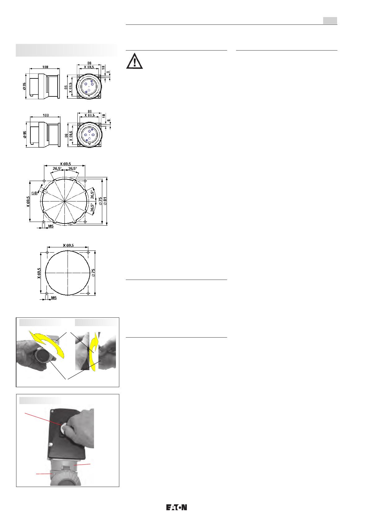
Fig. 1: Pour la mise en circuit de la prise, il faut
d’abord dévisser l’anneau à baïonnette, pos. 2
de la prise, pos. 1, et le déplier.
Fig. 2: Après avoir enfiché la fiche dans la prise,
l’anneau à baïonnette de la fiche, pos. 2, est
vissé jusqu’à sa butée sur la prise afin d’établir
l’indice de protection IP 66.
Pour la mise en circuit de la prise murale avec
interrupteur de verrouillage procédez comme
suit:
Fig. 1 et fig. 2, comme décrit ci-dessus.
Fig. 3: Puis, l’interrupteur pos. 3 est enclenché
et, par conséquent, la fiche est bloquée dans la
prise. Afin d’assurer le mode de protection
selon la plaque signalétique après la mise en
circuit de la prise avec la fiche mise en place,
l’anneau à baïonnette de la fiche, pos. 2, est
vissé jusqu’à sa butée sur la prise pos. 1.
Pour la mise hors circuit et pour retirer la fiche
de la prise murale à 4 pôles, procédez dans
l’ordre inverse. Après avoir séparé la fiche de la
prise, celle-ci doit être fermée avec le couvercle
à charnière et bloquée avec l’anneau à
baïonnette, afin d’établir l’indice de protection
IP 66.
La fiche ne peut être enfichée dans la prise
ou retirée de celle-ci que lorsque la prise est
mise hors circuit.
Seul l’utilisateur est responsable de l’emploi
comme prévu de cette fiche et prise.
Après un court-circuit dans le circuit, la
capabilité de fonctionner doit être vérifiée.
Pour l’emploi, les consignes des sections 3
et 4 devront être respectées.
Fiches et prises de 32 A, GHG 522
F
Connecteur à 3 pôles
Connecteur à 4 pôles
Gabarit de perçage pour prise à bride
Gabarit de perçage pour connecteur
Pos 3
Pos 2
Pos 1
Pos 1
Pos 2
Fig. 3
Fig. 1 Fig. 2
Dimensions en mm
X = dimensions de fixation
13
Des emplois autres que ceux décrits
ne sont admis qu’avec le consentement par
écrit de la part de COOPER CROUSE-HINDS.
Lors de l’exploitation, les instructions selon
point 7 de ce mode d’emploi doivent être
respectées.
En plein air, les fiches doivent être gardées avec
leur ouverture (côté des broches) vers le bas.
A l’option, elles peuvent être fermées avec les
capuchons protecteurs pour la fiche qui sont
disponibles sur demande (voir catalogue
général).
6 Installation
Pour l’installation et l’exploitation d’appareils
électriques pour atmosphère explosive, la
règlementation nationale en vigueur ainsi que
les règles de la technique généralement
reconnues devront être respectées.
6.1 Montage
Le montage des prises murales peut se faire
sans ouvrir l’enveloppe.
En cas de montage directement au mur, les
prises murales ne doivent reposer au niveau
du mur qu’en les points de fixation prévus. La
vis choisie doit correspondre au trou de fixation
(voir plan coté) et elle ne doit pas avarier
l’ouverture (par ex. emploi d’une rondelle).
Le dispositif doit être fixé en diagonale avec
au moins deux vis.
Le montage de la prise murale et de la prise
à bride doit se faire de sorte que l’ouverture
d’enfichage ne soit pas dirigée vers le haut.
Les prises murales avec interrupteur peuvent
être verrouillées par ressort sur le porte-appareil
CEAG, taille 5, en les poussant latéralement
dans la rainure de guidage du côté gauche du
porte-appareil.
Les instructions respectives pour le montage
devront être respectées.
6.2 Ouverture du dispositif/
Raccordement électrique
Le raccordement électrique du dispositif ne doit
se faire que par du personnel qualifié.
L’isolation doit couvrir le conducteur
jusqu’à la borne. Le conducteur lui-même ne
doit pas être endommagé.
En tenant compte des règlements respectifs,
les conducteurs dûment dénudés des câbles
sont raccordés.
Le raccordement électrique des fiches se fait
comme montré dans les figures 4 et 5.
Les vis de fixation (pos. 3, fig. 4) de l’insert
de la fiche (pos. 2, fig. 5) sont desserrées pour
le sortir de l’alvéole. Puis, l’insert peut être
raccordé aux connexions des contacts mâles
(voir vue 1, fig. 5).
Attention: En cas de perte des vis de fixation
(pos. 3, fig. 4) celles-ci doivent être rempla-
cées par des vis similaires ou être deman-
dées au fabricant.
Après le raccordement du câble, le montage se
fait dans l’ordre inverse
Le raccordement électrique des connecteurs se
fait comme montré dans les figures 6 à 8:
Fig. 6: Après avoir dévissé les deux vis pos. 3,
l’insert de commutation pos. 2 est sorti de la
bride pos. 2.
Fig. 7: Puis, les fils d’alimentation pos. 4
peuvent être raccordés aux bornes de l’insert
de commutation pos. 2, comme décrit sous
point 6.2.
Fig. 8: Enfin, l’insert de commutation pos. 2 est
vissé dans la bride pos. 1 au moyen des vis
auto-taraudeuses pos. 3 tout en respectant sa
position correcte.
Les sections minimales et maximales
admissibles des conducteurs doivent être
respectées (voir caractéristiques techniques).
Toutes les vis et/ou écrous des bornes de
connexion, aussi celles des bornes non
utilisées, doivent être serrées à fond.
Les bornes sont prévues pour le raccordement
de conducteurs en cuivre. En cas d’utiliser des
câbles de connexion multifilaires ou à fils de
faible diamètre, les bouts de fil doivent être
traités selon la règlementation nationale et
internationale y applicable (par ex. emploi des
embouts).
Fiches et prises de 32 A, GHG 522
F
Point de fixation A
Prise murale de 32A avec interrupteur
Pos 1
Pos 3
Pos 2
Pos 1 Pos 2
Pos 1
Pos 3
Pos 1
Pos 3
Pos 4
Pos 2
Pos 2 Pos 1
Pos 1
Pos 2
Pos 2
PE
L1
L2
L3
N
Vue 1 Vue 2
Fig. 4
Fig. 5
Fig. 6
Fig. 7
Fig. 8
A A
A A
14
6.3 Entrées de câble (KLE);
bouchons de fermeture
6.3.1 Fiche et prise
Pour des câbles flexibles il faudra utiliser des
presses-étoupes à trompette ou d’autres
entrées convenables avec décharge de
traction supplémentaire.
Lorsque des entrées de câble avec un indice de
protection IP inférieur à celui du dispositif sont
employées (voir page 3), l’indice de protection
IP de l’ensemble sera réduit.
Les directives pour le montage applicables aux
entrées de câble montées doivent être
respectées. Des ouvertures d’entrée non
utilisées doivent être fermées avec un bouchon
de fermeture pour établir l’indice de protection.
Lors du montage des entrées de câble il faudra
veiller à ce que des garnitures d’étanchéité
correspondant au diamètre du câble soient
utilisées. En cas de garnitures qui doivent être
coupées sur mesure, il faudra faire attention à
ce que la garniture soit adaptée au diamètre du
câble.
Les entrées de câble doivent être serrées à
fond pour maintenir l’indice de protection.
Au cas où elles seraient forcées, cela pourrait
être nuisible à l’indice de protection.
Toutes les entrées de câble métriques CEAG
non utilisées doivent être fermées avec un
bouchon de fermeture pour des entrées de
câble métriques.
6.3.2 Fiche
Fig. 9: Généralement, les garnitures pourvues
dans la fiche doivent être utilisées. Lors du
montage du câble, il faut faire attention à ce
que des garnitures convenables pour le
diamètre du câble soient employées. Après
avoir connecté le câble, la collerette de fixation,
pos 2, doit être vissée à la main jusqu’à ce que
l’étanchéité soit assurée. Puis, les vis, pos 4,
de la pince de décharge de traction, pos 3,
doivent être serrées à fond.
Attention! Un serrage excessif peut nuir à
l’effet de décharge de traction.
6.4 Fermeture du dispositif
Les vis du couvercle, de la fiche et du
prolongateur doivent être serrées à fond afin
d’assurer l’indice de protection minimum
requis.
Au cas où elles seraient forcées, cela pourrait
être nuisible à l’indice de protection.
Tout corps étranger doit être ôte du
dispositif.
6.5 Mise en service
Avant la mise en service du matériel, les
vérifications spécifiées dans les règlements
nationaux individuels devront être exécutées.
De plus, il faudra vérifier son fonctionnement et
installation corrects en conformité avec ce
mode d’emploi et avec d’autres règlements y
applicables.
Chaque fois que la fiche est enfichée dans la
prise, elle devra d’abord être vérifiée pour des
avaries.
L’utilisateur doit veiller à ce que le même
potentiel terrestre soit appliqué en tout lieu.
L’installation et l’exploitation inadéquates
des fiches et prises peut entraîner la perte
de la garantie.
7 Maintien / Entretien
Avant d’ouvrir l’enveloppe, débrancher le
dispositif de la tension ou prendre des
mesures préventives appropriées.
Les intervalles de service requis dépendent
de l’emploi spécifique et devront donc être
fixés par l’utilisateur en tenant compte des
conditions d’exploitation.
Si, lors d’un entretien, on constate que des
travaux d’entretien sont nécessaires, il faudra
suivre le point 8 de ce mode d’emploi.
8 Réparation / Remise en état
Des réparations ne doivent être exécutées
qu’à l’aide de pièces de rechange d’origine
CEAG.
Il n’est pas permis de transformer ou de
modifier ce matériel.
9 Évacuation des déchets /
Recyclage
Lors de l’évacuation de ce matériel électrique,
la règlementation nationale respective en
vigueur devra être respectée. Pour faciliter la
réutilisation des composants individuels, des
pièces en matière plastique sont repérées de
la marque distinctive de la matière plastique
employée.
Sous réserve de modification ou de supplé-
ment de cette série de produits.
Fiches et prises de 32 A, GHG 522
F
Codage de la tension et du nombre de pôles
selon CEI
Tension Couleur h (PE)
2 pôles + PE
110 - 130V 50/60Hz jaune 4 h
200 - 250V 50/60Hz bleu 6 h
3 pôles + PE
200 - 250V 50/60Hz bleu 9 h
480 - 500V 50/60Hz noir 7 h
380 - 415V 50/60Hz rouge 6 h
600 - 690V 50/60Hz noir 5 h
3 pôles + N + PE
480 - 500V 50/60Hz noir 7 h
380 - 415V 50/60Hz rouge 6 h
600 - 690V 50/60Hz noir 5 h
Pos 2
Pos 1 Pos 3 Pos 4
Fig. 9
15
Notizen / Notes / Remarques
Cooper Crouse-Hinds GmbH
Neuer Weg-Nord 49
69412 Eberbach
www.crouse-hinds.de
© 2016 Eaton
All Rights Reserved
Printed in Germany
dd
Publication No.
GHG 510 7002 P0003 D/GB/F (h)
Auflage / 17.2016 / CS
Eaton is a registered trademark.
All trademarks are property
of their respective owners.
Eaton is dedicated to ensuring that reliable, efficient
and safe power is available when it’s needed most. With
unparalleled knowledge of electrical power management
across industries, experts at Eaton deliver customized,
integrated solutions to solve our customers’ most critical
challenges.
Our focus is on delivering the right solution for the appli-
cation. But, decision makers demand more than just
innovative products. They turn to Eaton for an unwavering
commitment to personal support that makes customer
success a top priority. For more information, visit
www.eaton.com/electrical.
Changes to the products, to the information contained in this
document, and to prices are reserved; so are errors and omissions.
Only order confirmations and technical documentation by Eaton is
binding. Photos and pictures also do not warrant a specific layout or
functionality. Their use in whatever form is subject to prior approval
by Eaton. The same applies to Trademarks (especially Eaton, Moeller,
and Cutler-Hammer). The Terms and Conditions of Eaton apply, as
referenced on Eaton Internet pages and Eaton order confirmations.
CZ: "Tento návod k použití si m žete vyžádat
ve
svém mate ském jazyce u p íslušného
zastoupení spole nosti Cooper Crouse-
Hinds/CEAG ve vaší zemi."
DK: "Montagevejledningen kan oversættes til
andre EU-sprog og rekvireres hos Deres
Cooper Crouse-Hinds/CEAG leverandør"
E: "En caso necesario podrá solicitar de su
representante Cooper Crouse-Hinds/CEAG
estas instrucciones de servicio en otro idioma
de la Union Europea"
EST: "Seda kasutusjuhendit oma riigikeeles
võite küsida oma riigis asuvast asjaomasest
Cooper Crouse-Hindsi/CEAG esindusest."
FIN: "Tarvittaessa tämän käyttöohjeen käännös
on saatavissa toisella EU:n kielellä Teidän
Cooper
Crouse-Hinds/CEAG - edustajaltanne"
GR:
Cooper Crouse-
Hinds/CEAG"
H: "A kezelési útmutatót az adott ország
nyelvén a Cooper Crouse-Hinds/CEAG cég
helyi képviseletén igényelheti meg."
I: "Se desiderate la traduzione del manuale
operativo in un´altra lingua della Comunit à
Europea potete richiederla al vostro
rappresentante Cooper Crouse-Hinds/CEAG"
LT: Šios naudojimo instrukcijos, išverstos
J su
gimt
j kalb , galite pareikalauti atsakingoje
"Cooper Crouse-Hinds/CEAG" atstovyb
je savo
šalyje.
LV: "Šo ekspluat
cijas instrukciju valsts valod
varat piepras t j su valsts atbild gaj Cooper
Crouse-Hinds/CEAG p
rst vniec b ."
M: Jistg
u jitolbu dan il-manwal fil-lingwa
nazzjonali tag
hom ming and ir-rappre entant
ta' Cooper Crouse Hinds/CEAG f'pajji
hom.
NL: "Indien noodzakelijk kan de vertaling van
deze gebruiksinstructie in een andere EU-taal
worden opgevraagd bij Uw Cooper Crouse-
Hinds/CEAG - vertegenwoordiging"
P: "Se for necessária a tradução destas
instruções de operação para outro idioma da
União Europeia, pode solicita-la junto do seu
representante Cooper Crouse-Hinds/CEAG"
PL: Niniejsz
instrukcj obs ugi w odpowiedniej
wersji j
zykowej mo na zamówi
w
przedstawicielstwie firmy Cooper-Crouse-
Hinds/CEAG na dany kraj.
S: "En översättning av denna montage- och
skötselinstruktion till annat EU - språk kan vid
behov beställas från Er Cooper Crouse-
Hinds/CEAG- representant"
SK: "Tento návod na obsluhu Vám vo Vašom
rodnom jazyku poskytne zastúpenie spolo
nosti
Cooper Crouse-Hinds/CEAG vo Vašej krajine."
SLO: "Navodila za uporabo v Vašem jeziku
lahko zahtevate pri pristojnem zastopništvu
podjetja Cooper Crouse-Hinds/CEAG v Vaši
državi."
RUS:
"
При необходимости, вы можете запрашивать
перевод данного руководства на другом языке
ЕС или на русском от вашего
Cooper Crouse-Хиндс / CEAG - представителей."
  • Page 1 1
  • Page 2 2
  • Page 3 3
  • Page 4 4
  • Page 5 5
  • Page 6 6
  • Page 7 7
  • Page 8 8
  • Page 9 9
  • Page 10 10
  • Page 11 11
  • Page 12 12
  • Page 13 13
  • Page 14 14
  • Page 15 15
  • Page 16 16

Eaton Crouse-hinds series Operating Instructions Manual

Type
Operating Instructions Manual
This manual is also suitable for

Ask a question and I''ll find the answer in the document

Finding information in a document is now easier with AI

in other languages