7
SITE PREPARATION
Unpacking the Equipment
Remove the shipping carton and User’s Manual
from the equipment. Take care not to damage the
tubing connections when removing the carton.
Inspect for Damage
Inspect the equipment for damage prior to
installing the equipment at the job site. Verify
coil fi ns are straight. If necessary, comb fi ns to
remove fl attened or bent fi ns.
Preferred Location of the Outdoor Unit
Survey the job site to determine the best
location for mounting the outdoor unit. Overhead
obstructions, poorly ventilated areas, and areas
subject to accumulation of debris should be
avoided. The outdoor unit should be installed
no closer than 18 inches from the outside walls
of the facility and in an area free from overhead
obstructions to ensure unrestricted airflow
through the outdoor unit.
Facility Prerequisites
Electrical power supplied to the unit must be
adequate for proper operation of the equipment.
The system must be wired and provided with
circuit protection in accordance with local
building codes.
Minimum Circuit Ampacity
Electrical wiring to the equipment must be
compatible and in compliance with the minimum
circuit ampacity listed on the outdoor unit data
label.
Maximum Fuse / Circuit Breaker Size
Circuit protection for the outdoor unit must be
compatible with the maximum fuse/circuit breaker
size listed on the outdoor unit data label.
INSTALLING THE INDOOR UNIT
The indoor unit (air handler, furnace, etc.) should
be installed prior to the routing of refrigerant
piping. Consult the Installation Instructions of
the indoor unit for installation details.
INSTALLING THE OUTDOOR UNIT
Slab Mount
The site selected for a slab mount installation
requires a stable foundation and not subject to
erosion. The slab should be level and anchored
(if necessary) prior to installation on the slab.
Cantilever Mount
The cantilever mount should be designed with
adequate safety factor to support the weight of the
equipment, and for loads subjected to the mount
during operation. Installed equipment should
be adequately secured to the cantilever mount
and levelled prior to operation of the equipment.
GENERAL INFORMATION
Split System units are designed for use with a wide
variety of fossil fuel furnaces, electric furnaces,
air handlers, and evaporator coil combinations
equipped with variable speed blowers.
This unit has been designed and tested for
capacity and effi ciency in accordance with A.R.I.
Standards. This unit will provide many years of
safe and dependable comfort, providing it is
properly installed and maintained. With regular
maintenance, this unit will operate satisfactorily
year after year. Abuse, improper use, and/or
improper maintenance can shorten the life of the
appliance and create unsafe hazards.
To achieve optimum performance and minimize
equipment failure, it is recommended that periodic
maintenance be performed on this unit. The
ability to properly perform maintenance on this
equipment requires certain mechanical skills
and tools.
Please consult your dealer for maintenance
information and availability of maintenance
contracts. Please read all instructions before
installing the unit.
Outdoor Unit Selection
Each outdoor unit is shipped with a refrigerant
charge adequate to operate the outdoor section
with an indoor matching coil or air handler. These
units include the proper amount of refrigerant for
an additional 15 ft. of refrigerant lines the same
size as the valve fi ttings.
NOTE: DO NOT USE ANY PORTION OF THE
CHARGE FOR PURGING OR LEAK TESTING.
Matching coils and air handlers may be shipped
with a small holding charge to pressurize them to
keep out contaminants. To release the pressure,
read the indoor section installation instructions
carefully.
Liquid and Suction Lines
Refrigerant grade copper tubing should be used
when installing the system. Refrigerant suction
line tubing should be fully insulated.
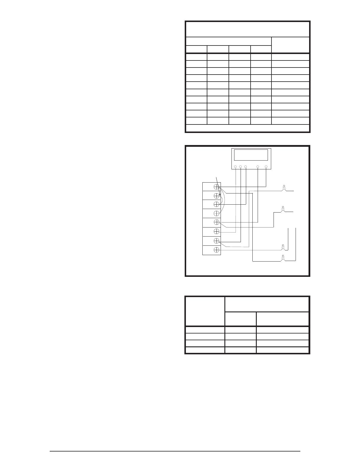
Field Connections for Electrical Power Supply
All wiring must comply with current provisions
of the “National Electrical Code” (ANSI/NFPA
70) and with applicable local codes having
jurisdiction. The minimum size of electrical
conductors and circuit protection must be in
compliance with information listed on the outdoor
unit data label.