
Installation Instructions
Split System Indoor Coils
CAUTION:
Read the Installation Instructions supplied with furnace/air handler and
observe all safety requirements outlined in instructions and/or furnace/air
handler markings before proceeding with installation of the coil
These instructions are primarily intended to assist qualifi ed individuals experi-
enced in the proper installation of this appliance. Some local and national codes
require licensed installation/service personnel for this type of equipment. Read
all instructions carefully before starting the installation.

2
Table of Contents
1. General Information ............................................................................................................... 3
2. Coil Specifi cations ................................................................................................................. 4
3. Coil Installation ....................................................................................................................... 5
• Upfl ow Furnace
• Downfl ow Furnace
• Horizontal Furnace
• Horizontal Ready Coils for Horizontal Left Installation
• Horizontal Ready Coils for Horizontal Right Installation
4. Verify Pressurization .............................................................................................................. 6
5. Refrigerant Line Connections ............................................................................................... 6
6. Completing the Installation ................................................................................................... 7
• Condensate Drain
• Air Filters
• Close-off Plates and Panels
• Refrigerant Charging
7. Maintenance and Service ...................................................................................................... 7

3
1. GENERAL INFORMATION
Standard cased coils are designed for upfl ow/
downfl ow applications or horizontal applications
when used in conjunction with our horizontal
drain pan kit (See page 5). Accessory kits are
not required for factory ready horizontal coils.
Coils are equipped with braze type refrigerant
connections for easy installation.
Read the installation manual supplied
with the outdoor unit for refrigerant line
connection procedure, required line sizes,
and other information pertaining to the system
installation.
1. Make certain that the air delivery of the
furnace/air handler is adequate to handle
the static pressure drop of the coil, fi lter, and
duct work.
2. Check the orifi ce size of the coil’s expansion
device and confi rm that it is suitable for
application with the intended outdoor unit.
NOTE: Some coils employ a thermostatic
expansion valve (TXV) as the metering
device (See page 4).
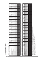
Figure 1.
3. Where precise forming of the refrigerant lines
is required, a copper tubing bender designed
for the size lines used is recommended.
Avoid sharp bends and contact of the
refrigerant lines with metal surfaces.
4. Refrigerant lines should be wrapped with
pressure sensitive neoprene or other
suitable material where they pass through
the raw edges of holes.
5. Coil must be level for proper condensate
drainage.
NOTE: Optional cooling/heating equipment must
be properly sized and installed in accordance
with the furnace manufacturer’s specifi cations
and approved recommendations. “Heating only”
furnace air circulators may have to be replaced
with multi-speed “Heating/Cooling” blowers to
upgrade the air delivery (CFM) when an add-on
coil is installed. Refer to Coil Specifi cations for
recommended CFM and allow for pressure drop
across the coil and fi lters.

4
2. COIL SPECIFICATIONS
TABLE 1 - C6 CASED COIL SPECIFICATIONS
Cased Coil Model Cased C6BA (1)(2)
T24-A T30-A
T24-B T30-B T36-B T42-B
T36-C T42-C T48-C T60-C T42-D T48-D T60-D
X24-A X30-A X35-A
X24-B X26-B X30-B X35-B X36-B X42-B
X36-C X42-C X48-C X60-C X42-D X48-D X60-D
Nominal Capacity BTUH (3)
24,000 30,000 36,000 24,000 24,000 30,000 36,000 36,000 42,000 36,000 42,000 48,000 60,000 42,000 48,000 60,000
Metering Device TXV TXV TXV TXV TXV TXV TXV TXV TXV TXV TXV TXV TXV TXV TXV TXV
Nominal Airfl ow (CFM) 800 1,000 1,000 800 1,200 1,000 1,200 1,200 1,400 1,200 1,400 1,600 2,000 1,400 1,600 2,000
W - Width (in.) 14 1/2 14 1/2 14 1/2 17 1/2 17 1/2 17 1/2 17 1/2 17 1/2 17 1/2 21 21 21 21 24 1/2 24 1/2 24 1/2
H - Height (in.) 20 3/4 20 3/4 20 3/4 20 3/4 26 3/4 20 3/4 20 3/4 26 3/4 26 3/4 26 3/4 26 3/4 30 1/4 30 1/4 30 1/4 30 1/4 30 1/4
HL - Height of Liquid Line (in.) 17 1/2 17 1/2 17 1/2 17 1/2 23 1/2 17 1/2 17 1/2 23 1/2 23 1/2 23 1/2 23 1/2 27 27 27 27 27
HS - Height of Suction Line (in.) 15 1/2 15 1/2 15 1/2 15 1/2 21 1/2 15 1/2 15 1/2 21 1/2 21 1/2 21 1/2 21 1/2 25 25 25 25 25
Connection - Liquid Line 3/8 3/8 3/8 3/8 3/8 3/8 3/8 3/8 3/8 3/8 3/8 3/8 3/8 3/8 3/8 3/8
Connection - Suction Line 3/4 3/4 3/4 3/4 3/4 3/4 3/4 3/4 3/4 7/8 7/8 7/8 7/8 7/8 7/8 7/8
Horizontal Drain Kit (4)
920265 920265 920265 920265 920266 920265 920265 920266 920266 920266 920266 920267 920267 920267 920267 920267
TABLE 2 - C6 HORIZONTAL CASED COIL SPECIFICATIONS
Cased Coil Model C6BH (1)(2)
T24-A T30-A T24-B T30-B T36-B T42-B T36-C T42-C T48-C T60-C T42-D T48-D T60-D
X24-A X30-A X35-A X24-B X26-B X30-B X35-B X36-B X42-B X36-C X42-C X48-C X60-C X42-D X48-D X60-D
Nominal Capacity BTUH (3)
24,000 30,000 36,000 24,000 24,000 30,000 36,000 36,000 42,000 36,000 42,000 48,000 60,000 42,000 48,000 60,000
Metering Device TXV TXV TXV TXV TXV TXV TXV TXV TXV TXV TXV TXV TXV TXV TXV TXV
Nominal Airfl ow (CFM) 800 1,000 1,000 800 1,200 1,000 1,200 1,200 1,400 1,200 1,400 1,600 2,000 1,400 1,600 2,000
W - Width (in.) 14 1/4 14 1/4 14 1/4 17 1/2 17 1/2 17 1/2 17 1/2 17 1/2 17 1/2 21 21 21 21 24 1/2 24 1/2 24 1/2
H - Height (in.) 26 3/4 26 3/4 26 3/4 26 3/4 20 3/4 26 3/4 26 3/4 26 3/4 26 3/4 26 3/4 26 3/4 30 1/4 30 1/4 30 1/4 30 1/4 30 1/4
HL - Height of Liquid Line (in.) 23 1/2 23 1/2 23 1/2 23 1/2 17 1/2 23 1/2 23 1/2 23 1/2 23 1/2 23 1/2 23 1/2 27 27 27 27 27
HS - Height of Suction Line (in.) 21 1/2 21 1/2 21 1/2 21 1/2 15 1/2 21 1/2 21 1/2 21 1/2 21 1/2 21 1/2 21 1/2 25 25 25 25 25
Connection - Liquid Line 3/8 3/8 3/8 3/8 3/8 3/8 3/8 3/8 3/8 3/8 3/8 3/8 3/8 3/8 3/8 3/8
Connection - Suction Line
3/4 3/4 3/4 3/4 3/4 3/4 3/4 3/4 3/4 7/8 7/8 7/8 7/8 7/8 7/8 7/8
(1) Refer to sales specifi cation sheets for Listed/Certifi ed combinations of equipment and required accessories.
(2) X in the model description designates factory installed TXV for R-410a refrigerant.
T in the model description designates factory installed TXV for R-22 refrigerant.
(3) Refer to the current ARI Directory for certifi ed ratings of split systems.
(4) Not required for "H" horizontal ready coils.

5
3. COIL INSTALLATION
WARNING:
Electric furnaces may be connected to
more than one supply circuit.
Upfl ow Furnace —
1. Disconnect all electrical power to the
furnace.
2. If needed, use one of the coil case adapter kits
to match the coil to the furnace air discharge
opening. Refer to the Coil Specifi cations
Section for proper kit numbers.
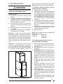
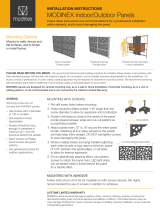
3. Install the coil and level it as needed to
ensure proper condensate drainage. (See
Figure 2)
4. Seal the enclosure as required to minimize
air leakage.
5. Connect the refrigerant lines as outlined in
the Refrigerant Lines section.
Downfl ow — These coils may be installed in
downfl ow applications. Installation of the coils in
these applications only require that the furnace
and coil cabinets are securely mounted together
before setting in place. Fossil fuel applications
require coil to be placed in the supply air stream
only.
Horizontal — Standard coils may also be
installed in horizontal applications. Installation
of the standard coils in these applications
only require that the furnace and coil cabinets
are securely mounted together and that a
horizontal drain pan kit be installed. Refer to the
Specifi cations Section for proper kit numbers.
To Confi gure Horizontal Ready Coils for
Horizontal LEFT Installations:
1) Remove the coil access door.
2) IMPORTANT: Remove the plug from one of
the threaded holes in the horizontal drain
pan. Completely remove the webbing located
in the threaded holes of the horizontal drain
pan. If webbing is not removed, the drain will
not function properly and ceiling damage
may occur.
3) Insert a plug (from the horizontal drain pan)
into the open and unused drain hole in the
drain pan at the bottom of the unit to block
bypass air.
4) Remove the corresponding drain line
knockout from the coil access door to allow
access to the horizontal drain.
5) Replace the door.
NOTE: Install drainpan extension (supplied) on
the following models:
C5BH-*60 C4BH-X36
C5BH-*49 C4BH-X48
C4BH-X60
To Confi gure Horizontal Ready Coils for
Horizontal RIGHT Installations:
1) Remove the coil access door. Unscrew the
line-set tube close-off plate from the front
left cabinet rail.
2) Slide the coil and drain pan assembly out
of the unit.
3) IMPORTANT: Remove the plug from one of
the threaded holes in the horizontal drain
pan. Completely remove the webbing located
in the threaded holes of the drain pan. If
webbing is not removed, the drain will not
function properly and ceiling damage may
occur.
4) Remove the sheet metal hairpin covers
(if supplied) from the back of the coil and
discard.
5) Place the horizontal drain pan on the
opposite side of the coil. On units with 2
sets of knockouts, remove the other set of
knockouts in the coil spacing plates and
insert support rod.
6) Insert a plug (from the horizontal drain pan)
into the open and unused drain hole in the
drain pan at the bottom of the unit to block
bypass air.
7) Slide the coil and the horizontal drain pan
assembly back into the unit. Reattach the
tube close off plate.
Figure 2. Upfl ow Furnace Application

6
8) Remove the corresponding drain line
knockout from the coil access door to allow
access to the horizontal drain.
9) Replace the door.
NOTE: Install drainpan extension (supplied) on
the following models:
C5BH-*60 C4BH-X36
C5BH-*49 C4BH-X48
C4BH-X60
Note: All condensate pans have primary and
secondary drain connections to meet FHA
requirements. If the application is located in
or above a living space where damage may
result from condensate overfl ow, a separate
3/4 inch drain must be provided from the
secondary drain connection and a secondary
drain pan must be installed under the entire
unit. Run secondary drain lines to a place
where they are noticeable if used.
4. VERIFY PRESSURIZATION
WARNING:
This coil is pressurized with Nitrogen.
Avoid direct face exposure or contact
with valve when gas is escaping.
Always ensure adequate ventilation
is present during the depressurization
process. Any uncertainties should be
addressed before proceeding.
VERIFY PRESSURIZATION:
- Test by depressing Schrader valve and listen
for escaping gas
- If no pressure is found, test coil for leak
- If no leak is found, install coil
- If leak is found, clearly mark leak
location and return coil to your distributor
for processing
5. REFRIGERANT LINE
CONNECTIONS
WARNING:
This coil is pressurized with Nitrogen.
Avoid direct face exposure or contact
with valve when gas is escaping.
Always ensure adequate ventilation
is present during the depressurization
process. Any uncertainties should be
addressed before proceeding.
Line Connections:
1. Making note of orientation, remove the hole
grommet from around the refrigerant line set
connection.
2. Remove the valve cap from the end of the
liquid line. Relieve all pressure from the coil by
depressing the valve.
3. Remove the valve core and valve core holder on
the liquid line. DO NOT reuse the valve, threaded
valve holder or O-Ring.
4. It is recommended to wrap a wet rag around
the suction line between the sensing bulb
and the line set braze joint before applying
any heat.
5. Unbraze and remove the cap on the suction
line.
6. Properly dispose of all removed parts.
7. Cut the line set tubing to the proper
length. Be sure that the tubing has been
sized in accordance with the outdoor unit
specifi cations.
8. Inspect both refrigerant lines. The ends of
the lines must be round, clean, and free of
any burrs.
9. Place grommets in proper orientation onto
line set with suffi cient distance to braze
joint.
10. Insert the suction line set tube into the coil
suction tube stub until it bottoms out.
11. Slip the nut from the schrader valve holder
onto the liquid line - check for correct
orientation. Insert liquid line into liquid line
stub until it bottoms out. Liquid line stub is
shipped with the coil but is not attached.
NITROGEN
HEALTH
FLAMMABILITY
REACTIVITY
0 Minimal Hazard
1 Slight Hazard
1
0
0
NITROGEN
HEALTH
FLAMMABILITY
REACTIVITY
0 Minimal Hazard
1 Slight Hazard
1
0
0

7
12. Braze the individual connections with
dry nitrogen fl owing through the joints to
eliminate internal oxidation and scaling.
13. Fasten nut to secure the liquid line to the
bulkhead fi tting. No O-Ring is required.
14. Check the assembly for leaks.
15. On horizontal applications of models with
TXV valve, re-position the sensing bulb on
the suction line so it is in the 4 o'clock or 8
o'clock position on the suction tube.
16. Properly dispose of all removed parts.
6. COMPLETING THE INSTALLATION
CAUTION:
The indoor coil must be checked to
ensure a level installation. Failure to do
so may result in improper condensate
disposal, causing structural damage,
premature equipment failure, or
possible personal injury.
Condensate Drain —
1. The coil condensate pan is furnished with
3/4" NPSC drain connections. Use a PVC
or similar material fi tting to attach the drain
line to the pan. The fi tting should be hand
tightened only. Overtightening may crack
the drain pan and cause a condensate
leak.
2. Connect the drain line and run to a suitable
drain avoiding sharp bends and pinching of
the line. Install a condensate trap and prime
with water.
3. During the system checkout, inspect the
drain line and connections to verify proper
condensate disposal.
4. Perform any necessary adjustments to the
coil components to ensure that all drip points
fall within the outline of the drain pan.
Air Filter — Air fi lters are not provided as an
integral part of this coil, however, a fi lter must
be installed upstream of the coil and inspected
frequently. When the fi lter becomes clogged with
dust or lint, it should be replaced (disposable type)
or cleaned (washable type). The fi lter should be
inspected and replaced or cleaned at least twice
during the year, generally at the start of each
heating and cooling season.
Close-Off Plates and Panels — Install the
necessary air close-off plates around the
refrigerant lines and drain line where required.
Reinstall all inner and outer panels of the coil
case and furnace that were previously removed
to install the indoor coil.
Refrigerant Charging — These cased indoor
coils are not factory charged with refrigerant.
It will be necessary to evacuate the indoor coil
and line set prior to charging. Refer to the outdoor
unit installation manual for detailed charges and
instructions.
7. MAINTENANCE AND SERVICE
WARNING:
Ensure that all electrical power to the
furnace and outdoor (condensing)
unit is off before performing any
mainte
nance or service on the
system.
To ensure optimum performance and to minimize
possible equipment failure, the following periodic
maintenance should be performed on this
equipment:
1. The air fi lter installed with the system should
be checked and cleaned or replaced twice
per year.
2. Check the coil, drain pan, and condensate
drain line for cleanliness at the start of
each heating and cooling season. Clean
as needed.
CAUTION:
Do not operate the system without
having a suitable fi lter in place in
the return air duct system. Always
replace the fi lter with the same size
and type.

INSTALLER: PLEASE LEAVE THESE
INSTALLATION INSTRUCTIONS WITH
THE HOMEOWNER
708823D (Replaces 708823C)
Specifi cations and illustrations subject to change
without notice and without incurring obligations.
Printed in U.S.A. (07/08)
O'Fallon, MO
¢7088230¤
708823D
-
 1
1
-
 2
2
-
 3
3
-
 4
4
-
 5
5
-
 6
6
-
 7
7
-
 8
8


Frigidaire C6B(A,H)-T Installation guide
- Type
- Installation guide
- This manual is also suitable for
Ask a question and I''ll find the answer in the document
Finding information in a document is now easier with AI
Related papers
-
Broan C6B(A,H)-T Installation guide
-
Broan C6B(A,H)-T Installation guide
-
Broan C6B(A,H)-F Installation guide
-
-
Broan C6BH-I Installation guide
-
-
Broan C5B(A,H) Installation guide
-
Broan C6B(A,H)-T Installation guide
-
-
Other documents
-
 GEARVITA T42 Hard reset manual
-
Intertherm C3(D,Q)-0 Installation guide
-
Bryant 311AAV User manual
-
 Modinex USAMOD2C Operating instructions
-
Intertherm FE/E1/E2 Heater Kit Installation guide
-
Unbranded Quick Reference Guide HP User guide
-
Broan C3(D,Q)-0 Installation guide
-
-
COMFORT-AIRE MWG36TC-B Installation, Operation & Maintenance Manual
-
 Modinex USAMOD5E Installation guide


