Reznor F Installation guide

Type
Installation guide

This manual is also suitable for

Form I-OPT-MH, P/N 102247 R8, Page 1
Applies to: Models LDAP, UDAP, APD, UDAS,
UDBP, UDBS, UEAS, F, B, VR
Description/
Application
These options are designed to permit the control of up to six heaters (one "Primary" heater
and one to ve "Secondary" units; see note for LDAP limitations) with one single-stage ther-
mostat or with a time clock and single or multiple single-stage thermostats. For maximum
safety, the multiple control is done in the low voltage circuit. (Interruption of the supply volt-
age is not recommended.) Wiring lengths may not exceed those shown in the table on page
8. DO NOT use these multiple heater control options with a two-stage gas valve or a
two-stage thermostat.
Kit Components
by Model
Check the components
against the list for the
model being installed.
Model LDAP
Model UDAP & APD
Model UDAS
Model UDBP
Model UDBS
Model UEAS
Model F
Model B
Model VR
Installation of Multiple Heater Control, Options CL31 and CL32
Form I-OPT-MH (2-16)
Obsoletes Form I-OPT-MH (Version D.2)
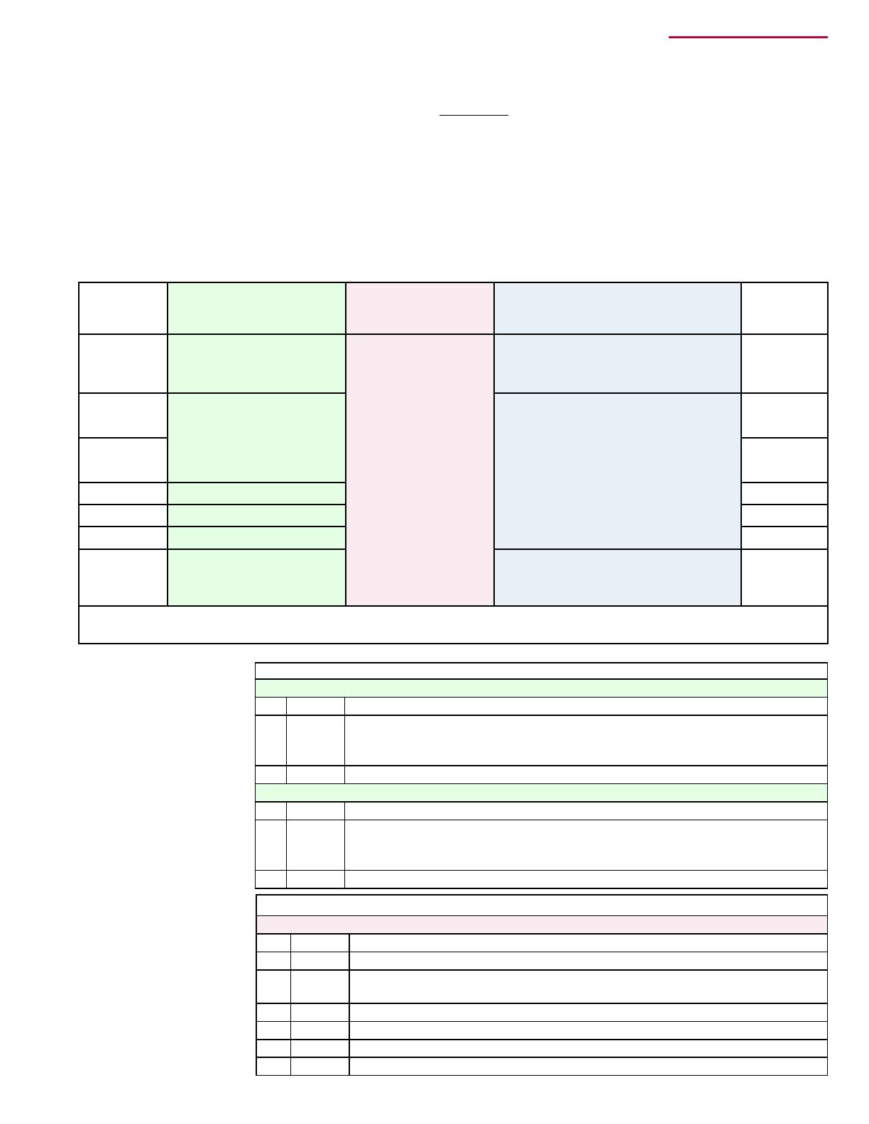
Application
by Voltage
& Model
Model LDAP
Models UDAP, APD,
UDAS, UDBP,
UDBS, and UEAS**
Models F, B, and VR
Application
by Voltage
& Model
115/1 N/A
CL31 for both the
Primary and 1st
Secondary Heater
plus a CL32 each
for the 2nd, 3rd, 4th,
and 5th Secondary
Heaters.
CL31 for both the Primary and 1st
Secondary plus a CL32 each for 2nd,
3rd, 4th, and 5th Secondary Heaters.
115/1
208/1
CL31 for both the Primary
and 1st Secondary Heater
plus a CL32 each for the
2nd, 3rd, 4th, and 5th
Secondary Heaters. *
CL32 for the Primary Heater plus
CL32 each for 1st, 2nd, 3rd, 4th, and
5th Secondary Heaters.
208/1
230/1 230/1
208/3 N/A 208/3
230/3 N/A 230/3
460/3 N/A 460/3
575/3 N/A
CL31 for both the Primary and 1st
Secondary plus a CL32 each for 2nd,
3rd, 4th, and 5th Secondary Heaters.
575/3
* Model LDAP 400 can have ve secondary heaters; Model LDAP 800 can have a maximum of three secondary
heaters; and Model LDAP 1200 can have a maximum of two secondary heaters. ** Model UEAS is 115 volt only.
Kits for Model LDAP
Option CL31 for LDAP - Pkg P/N 208366 for Primary and One Secondary Unit
Qty P/N Description
2 208365 Relay Assemblies each consisting of one P/N 18549 relay, with attached
42" red wire, 42" white wire, 6" blue wire, and 6" brown wire -- all with
terminals.
2 208185 Wiring Diagram Label
Option CL32 for LDAP - Pkg P/N 208367 for each Additional Secondary Unit
Qty P/N Description
1 208365 Relay Assemblies each consisting of one P/N 18549 relay, with attached
42" red wire, 42" white wire, 6" blue wire, and 6" brown wire -- all with
terminals.
1 208185 Wiring Diagram Label
Kits for Models UDAP, APD, UDAS, UDBP, UDBS, UEAS
Opt CL31 for UDAP/ APD/UDAS/UEAS - Pkg P/N 197155 for Primary & One Secondary Heater
Qty P/N Description
1 194808 Transformer 40VA
2 197157 Relay Assemblies each consisting of one P/N 18549 relay, wired and
mounted on a specially designed bracket.
2 195249 Self-drilling screw for attaching relay bracket
2 16228 Cable Clamp 3/16"
2 197164 Wiring Diagram Label
1 197160 Wiring Harness Assembly (brown wires)
Form I-OPT-MH, P/N 102247 R8, Page 2
Kit Components by
Model (cont'd)
Kits for Models UDAP, APD, UDAS, UDBP, UDBS, and UEAS (cont'd)
Opt CL31 for UDBP/UDBS – Pkg P/N 202958 for Primary & One Secondary Heater
Qty P/N Description
2 197157 Relay Assemblies each consisting of one P/N 18549 relay, wired and
mounted on a specially designed bracket.
2 195249 Self-drilling screw for attaching relay bracket
2 16228 Cable Clamp 3/16"
2 197164 Wiring Diagram Label
1 197160 Wiring Harness Assembly (brown wires)
Opt CL32 for UDAP/APD/UDAS/UDBP/UDBS/UEAS – Pkg P/N 197156 for Each
Additional Secondary Heater
Qty P/N Description
1 197157 Relay Assembly consisting of one P/N 18549 relay, wired and
mounted on a specially designed bracket.
1 195249 Self-drilling screw for attaching relay bracket
1 16228 Cable Clamp 3/16"
1 197164 Wiring Diagram Label
Kits for Model VR
Option CL31 for VR – Pkg P/N 205685 for Primary and One Secondary Heater
Qty P/N Description
2 102243
Relay Assemblies each consisting of one P/N 18549 relay, wired and
mounted on a specially designed bracket.
1 194808 Transformer 40VA
1 16354 Twist-on Wire Connector (Orange)
4 98872 Spacers
4 121033 Screws #8 x 1" lg
2 16228 Cable Clamp 3/16"
2 197164 Wiring Diagram Label
Option CL32 for VR – Pkg P/N 205686 for Each Additional Secondary Heater
Qty P/N Description
1 102243 Relay Assembly consisting of one P/N 18549 relay, wired and
mounted on a specially designed bracket.
2 98872 Spacers
2 121033 Screws #8 x 1" lg
1 16228 Cable Clamp 3/16"
1 197164 Wiring Diagram Label
Kits for Models F and B
Option CL31 for Models F & B – Pkg P/N 102248 for Primary and One Secondary
Heater
Qty P/N Description
1 102708 Transformer 35VA – Basler #BE141640-RAK
2 103152 Sheetmetal Screws, #6 x 1-1/2 “ long (for transformer)
2 111233 Tinnerman Clips, #C1110-62 (for transformer screws)
2 102243 Relay Assemblies each consisting of one P/N 18549 relay, wired and
mounted on a specially designed bracket.
2 16228 Cable Clamp 3/16"
2 131127 Wiring Diagram Label
Option CL32 for Models F & B – Pkg P/N 102249 for Each Additional Secondary
Heater
Qty P/N Description
1 102243 Relay Assembly consisting of one P/N 18549 relay, wired and
mounted on a specially designed bracket.
1 16228 Cable Clamp 3/16"
1 131127 Wiring Diagram Label
Form I-OPT-MH, P/N 102247 R8, Page 3





























































FIGURE 1A - Control Compartment showing Transformer Location, Models UDAP, APD, UDAS, and
UEAS "Primary" Heater
The transformer is mounted on the control board on the bottom of the control compartment.
These instructions are designed to assist a qualied electrician in installing this multiple
heater control kit. All electrical wiring and connections, including electrical grounding,
MUST be in accordance with the National Electric Code ANSI/NFPA No. 70 (latest edi-
tion) or, in Canada, with the Canadian Electrical Code, Part 1-C.S.A. Standard C22.1 In
addition, the installation must comply with local ordinances and applicable gas company
requirements.
Follow the instructions that apply to the option and model of heater.
1. Turn off the gas and electric power.
2. Change the Transformer (does not apply to Model LDAP, UDBP, or UDBS) –
applies to OPTION CL31 installation on the "Primary" unit only
Refer to the illustration (FIGURE 1A, 1B, or 1C) for the unit being serviced.
Remove or open panels as required and locate the factory-installed transformer.
Mark and disconnect the wires. Remove the transformer.
Using the same screws (except Models F and B; see FIGURE 1C), install the 35 or
40 VA transformer from the kit. Connect the wires. Close the panel.
Installation
Instructions
WARNING
Improper installation, adjustment, alteration, service or maintenance can cause property
damage, injury, or death. Read the installation, operation, and maintenance instructions
thoroughly before installing or servicing this equipment.
Form I-OPT-MH, P/N 102247 R8, Page 4
Installation
Instructions (cont'd)
FIGURE 1C - Transformer Location, Model F or B "Primary" Heater
Rear View
Transformer
Terminal
Strip
Remove the left outer side panel
(left when facing the rear of the
heater), exposing the inner side
panel and the wiring.
Locate the factory-installed
transformer. Mark and disconnect
the wires. Remove the transformer.
Through the “large” hole in the
side panel (for mounting the
transformer), slide the Tinnerman
clips over the new transformer.
Attach with the screws included in
the kit. Connect the wires to the new
transformer.
Replace the outer side panel.



















FIGURE 1B -
Bottom View
showing
Transformer
Location, Model
VR "Primary"
Heater
2. Change the Transformer (cont'd)
Form I-OPT-MH, P/N 102247 R8, Page 5
FIGURE 2A - Model LDAP
Remove the access panel from
the main heat section.
Locate the position on the
control panel for the new relay.
Attach the relay with the
screws provided in the kit.
3. Install a Relay or Relay Bracket Assembly on the “Primary” Unit and all
“Secondary” Units – Option CL31 and Option CL32. Select the appropriate
FIGURE (2A, 2B, 2C, or 2D) for the Model of Heater.




































FIGURE 2B - Models UDAP, APD,
UDAS, UDBP, UDBS, UEAS
Model UD Sizes 30, 45, 60, 75,
100, 125 - On the rear of the
heater, position the bracket as
illustrated.
Remove the screws from the edge
of the cabinet bottom.
Re-insert the screws attaching the
relay bracket.
Model UD Sizes 150, 175, 200,
225, 250, 300, 350, 400 and all
UEAS - On the rear of the heater,
position the bracket as illustrated.
Remove the screw on the left from
the edge of the cabinet bottom.
Re-insert the screw attaching the
bracket.
Secure the other side of the
bracket with the self-drilling screw
in the kit.
Form I-OPT-MH, P/N 102247 R8, Page 6

















FIGURE 2C - Model VR
On the end of the burner/control box, remove and
discard the screws holding the thermostat terminal strip.
Use the screws and spacers in the option package to
attach the relay bracket and to re-attach the terminal
strip. Follow the sequence below, starting at the burner/
control box
- rst the terminal strip,
- second the spacers,
- third the relay bracket,
- and fourth (on the left side only) – put the blue and
brown wires through the plastic cable clamp and
position the cable clamp on top of the relay bracket.
FIGURE 2D - Model F or B
On the rear of the heater, remove the screws
that hold the thermostat terminal strip. Slide
the relay bracket underneath the terminal strip.
Re-insert the screw on the right side. Put the
blue and brown wires into the plastic cable
clamp, and on the left end of the terminal strip,
position the cable clamp on top. Fasten with the
other screw.











NOTE: The 1" long screws and the spacers in the
option package will not be used.
4. Wiring Diagram Label – All Heaters
Installation
Instructions (cont'd)
See FIGURE 3A, 3B, or 3C for Option CL31 and CL32 wiring diagram.
Model FIGURE Label
LDAP ................3A ...............208185
UDAP & APD .... 3B ...............197164
UDAS ................ 3B ...............197164
UDBP ................3B ...............197164
UDBS ................ 3B ...............197164
UEAS ................3B ...............197164
VR .....................3B ...............197164
F ........................ 3C ...............131127
B .......................3C ...............131127
Select the wiring diagram for the model of heater being installed. Check the
appropriate box on each diagram for the heater function (Primary or Secondary).
Adhere the label in the location specied below for the model of heater .
Packaged Model LDAP – Position the label (P/N 208185) on the inside of the access
panel. Wipe the area with a clean, dry cloth. Remove the backing and adhere the
wiring diagram.
Unit Heater Models UDAP, APD, UDAS, UDBP, UDBS, and UEAS – Position the
label (P/N 197164) on the bottom rear corner of the access panel. Wipe the area with
a clean, dry cloth. Remove the backing and adhere the wiring diagram.
Infrared Heater Model VR – Position the label on the rear of the burner box above
the terminal strip. Wipe the area with a clean, dry cloth. Remove the backing and
adhere the wiring diagram.
NOTE: The spacers are required to allow the access door to open.
3. Install a Relay or Relay Bracket Assembly (cont'd)
Form I-OPT-MH, P/N 102247 R8, Page 7
FIGURE 3A- Multiple
Heater Control Wiring
Diagram Label for Model
LDAP, P/N 208185
Label
208185
CHECK APPROPRIATE BOX:
PRIMARY HEATER SECONDARY HEATER
SECONDARY
HEATER
4
2
3
1
PRIMARY
HEATER
1
4
3
2
1W1WR
R
7
CRIMP TERMINAL
BR BR BR BR
RLBLBLBLB
R
R
CONTROL DEVICE
OR OTHER
THERMOSTAT
RR
BL
WRB
W
RBL
BR
FIELD SUPPLIED WIRING
FIELD WIRING HAVING A MINIMUM TEMPERATURE RATING OF AT LEAST 105 DEGREES C.
SHALL BE USED. SUPPLY CIRCUIT WIRING SHALL HAVE A MINIMUM SIZE OF 18 AWG.
ADDITIONAL
SECONDARY HEATERS
TO
TIME CLOCK
CONTACTS
OPTIONAL
DEVISE
CONTROL
OR OTHER
WD# 189578
For future identication,
check appropriate box on
each wiring diagram label.
Unit Heater Models F and B – Position the label (P/N 131127) in the lower right
corner of the outer left side panel (left when facing the rear of the heater). Wipe the
area with a clean, dry cloth. Remove the backing and adhere the wiring diagram.
5. Control Wiring - All Models
Follow the diagram label to wire the controls.
FIGURE 3B - Multiple
Heater Control Wiring
Diagram Label for
Models VR, UDAP, APD,
UDAS, UDBP, UDBS,
and UEAS, P/N 197164
PRIMARY HEATER SECONDARY HEATER
SECONDARY
HEATER
PRIMARY HEATER
TO COMMON SIDE
OF TRANSFORMER
TO “COM” ON
DSI CONTROL
TO ADDITIONAL
SECONDARY
HEATERS
THERMOSTAT
OR OTHER
CONTROL DEVICE
Label
197164
For future identication,
check appropriate box on
each wiring diagram label.
(NOTE: VR Models do
not have a "W2" terminal.
Splice between the DSI
control "COM" and 24V on
the transformer and use
the twist-on wire connector
provided to connect the
wires.
Form I-OPT-MH, P/N 102247 R8, Page 8
131127
CHECK APPROPRIATE BOX:
PRIMARY HEATER SECONDARY HEATER
REV #2
42
3 1
PRIMARY
HEATER
3
4
1
2
R W1 W1 R
GRD STRIP
OR G67
ON G77
BR
BR BR BR BR
BL BL BL BL R
R
R
CONTROL DEVICE
OR OTHER
THERMOSTAT
RR
BL
BR W
W
RBL
BR
FIELD SUPPLIED WIRING
FIELD WIRING HAVING A MINIMUM TEMPERATURE RATING OF AT LEAST 105 DEGREES C.
SHALL BE USED. SUPPLY CIRCUIT WIRING SHALL HAVE A MINIMUM SIZE OF 18 AWG.
ADDITIONAL
SECONDARY HEATERS
TO
TIME CLOCK
CONTACTS
OPTIONAL
DEVISE
CONTROL
OR OTHER
NOTE #1
NOTE #1: ON STANDING PILOTS MODELS, ATTACH TO BROWN WIRE ON GAS VALVE.
HEATER
SECONDARY
FIGURE 3C - Multiple
Heater Control Wiring
Diagram Label for
Models F and B,
P/N 131127
For future identication,
check appropriate box on
each wiring diagram label.
Installation
Instructions (cont'd)
Do not exceed the control wire lengths shown in the table.
CAUTION: Be careful not to short thermostat leads to a metal
surface. Doing so will cause the transformer to fail, requiring it to
be replaced.
6. Turn on the electric power and the gas. Follow the lighting instructions to
operate the heater.
Check the control system for proper and safe operation.
Field Control Wiring (Length and Gauge)
Wire Type Wire Gauge Maximum Wire Length* Maximum Distance
TEW 18 500 ft (152M) 250 ft (76M)
TEW 14 1300 ft (457M) 650 ft (198M)
TEW 12 2100 ft (640M) 1050 ft (320M)
*Wire length equals wire for circuit going plus wire for returning circuit.
5. Control Wiring (cont'd)
Specications & illustrations subject to change without notice and without incurring obligations.
©Nortek Global HVAC, LLC 2016. All rights reserved.
All marks are the property of their respective organizations.
O’Fallon, MO I Printed in U.S.A. (2/16)
Form I-OPT-MH (2-16)
  • Page 1 1
  • Page 2 2
  • Page 3 3
  • Page 4 4
  • Page 5 5
  • Page 6 6
  • Page 7 7
  • Page 8 8

Reznor F Installation guide

Type
Installation guide
This manual is also suitable for

Ask a question and I''ll find the answer in the document

Finding information in a document is now easier with AI