Installation Instructions
1690 Touchbar
Concealed Vertical Rod
Panic Device
Index:
• Parts List ...................................
• Touchbar Part Numbers ............
• Before Installation .....................
• Installation.................................
• Touchbar Dogging ...................
• Setting Rod Lengths ................
• Re-handing Device..................
• Field Sizing Device ..................
• 1990 Retrofit Instructions ........
• Template ..................................
NOTE: The door prep for the 1690 Hex Bottom Rod is different
than for the RL bottom rod. Please verify rod type in package
and prep required (page 16) before prepping the door.
ININST.1002
Copyright © 2010 Ingersoll-Rand Company.
All rights reserved.
ININST.1002(G)
2
3
3
4
10
11
11
12
14
16

ININST.1002(G) Page 2 of 16
PARTS LIST
1. See page 3 for touchbar
part numbers.
2. Touchbar shown cut away
for visibility.
NOTES
!
RHR shown
Top Rod
Assembly
12
13
15
14
6
26
27
16
17
11
9
5
1
8
7
4
10
22
10
2
3
24
23
21
25
RL Bottom
Rod
Assembly
18
24
23
20
19
RIM CYLINDER
(optional; sold separately)
Finish Part No.
DC13 4270107367
DC35 4270105986
US4
032210-10
US10 032210-06
US26/28 4270100247
Hex Bottom
Rod
Assembly
Package No. PKG.150 (US28 finish) or
Package No. PKG. 151 (DC13/DC35 finish)
Item Quantity Description Part No.
1 4 #10-32 x 1/4" UFPHMS
US28 finish 963125-00
DC13/DC35 finish 4270902255
2 2 Rod bearing bushing BUSH.108
3 4 Retaining ring RRING.108
4 2 1/4-20 x 1/2" FPHMS SCREW.1052
5 1 Traveler lift bracket BRKT.138
6 1 5/32" hex dogging key 4270106944
Package No. CYLASY.1083
Note: Optional. Required with rim cylinder only.
Item Quantity Description Part No.
7 1 Cylinder bushing 4270100663
8 1 Pinion cam 4270100566
9 1 Retractor 4270903161
10 1 Retainer screw SCREW.1049
11 1 Pinion support bracket
BRKT.133
Package No. 4270902993
Note: For use with EO and DT devices only.
Item Quantity Description Part No.
10 1 Retainer screw SCREW.1049
11 1 Pinion support bracket
BRKT.133
Package No. ECAP.130
Item Quantity Description Part No.
12 2 1/4-20 x 1/2" PPHMS 4299100074
13 1 Channel end cap ECAP.127
14 1 Hinge stile touchbar end cap
ECAP.128
15 2 #8 x 1-1/4" FPHTF
4299101314
Package No. COVER.113
Item Quantity Description Part No.
16 1 Center case cover COVER.112
17 2 #8 x 5/8" PPHTC Sems 4299101318
Item Quantity Description Part No.
21 1 Lift arm
BRKTASSY.107
22 2 #8 x 3/4" FPHTF 4299101313
23 2 Touchbar pin PIN.125
24 2 Touchbar anchor BRKT.128
25 1 Lock stile touchbar end cap ECAP.129
26 1 Dogging spring 971493-89
27 1 Dogging assembly
DC13/DC35 finish KIT.1022
US28 finish KIT.1021
Package No. 4270107176 (US28 finish) or
Package No. 4270107178 (DC13/DC35 finish)
Item Quantity Description Part No.
19 1 Hex rod guide 4270101829
20 2 #10-24 x 3/8" UFPHTC Typ F Stl
US28 finish 4299100746
DC13/DC35 finish 4299101027
Package No. PB48
Note: Contains strike, three shims, and four mounting screws.
Item Quantity Description Part No.
18 1 Strike
US28 finish 4270108353
P13 finish 4270108354
P35 finish 4270108355

ININST.1002(G) Page 3 of 16
TOUCHBAR PART NUMBERS
BEFORE INSTALLATION
1. Check "Parts List" (see page 2).
2. Prepare door using template on page 16.
3. Set initial rod lengths (see page 11). Rods are factory set for standard 7' door.
4. If door width is non-standard, cut device (see page 12).
5. If necessary, re-hand device (see page 11).
PARTS LIST (CONTINUED)
DC13
DC35
US3
US10
US26
US26D
US28
30" Nominal Device Length
(24.785" Extrusion Length)
Finish
Without
Dogging
Hole
With
Dogging
Hole
EXT.399 EXT.609
EXT.400 EXT.631
EXT.2324 EXT.2355
EXT.2334 EXT.2356
EXT.2339 EXT.2357
EXT.2289 EXT.2358
EXT.398 EXT.608
36" Nominal Device Length
(30.785" Extrusion Length)
Without
Dogging
Hole
With
Dogging
Hole
EXT.825 EXT.828
EXT.826 EXT.829
EXT.2323 EXT.2351
EXT.2333 EXT.2352
EXT.2338 EXT.2353
EXT.2340 EXT.2354
EXT.830 EXT.827
Without
Dogging
Hole
With
Dogging
Hole
Without
Dogging
Hole
With
Dogging
Hole
42" Nominal Device Length
(36.785" Extrusion Length)
EXT.439 EXT.736
EXT.441 EXT.737
EXT.2341 EXT.2359
EXT.2345 EXT.2360
EXT.2349 EXT.2361
EXT.2350 EXT.2362
EXT.438 EXT.646
48" Nominal Device Length
(42.785" Extrusion Length)
EXT.443 EXT.739
EXT.444 EXT.740
EXT.2298 EXT.2363
EXT.2303 EXT.2364
EXT.2304 EXT.2365
EXT.2294 EXT.2366
EXT.442 EXT.738
HEX BOTTOM
ROD ASSEMBLY
Bent rod 37.812" long
4270101825
(can be shortened by 6")
Jam nut 3/8"-24
4299100004
Hex bolt
BOLT.1004
RL BOTTOM
ROD ASSEMBLY
Bent rod 35.125" long
4270100017
(can be shortened by 5")
Jam nut 3/8"-24
4299100004
RL bottom latch
4270100521
TOP ROD
ASSEMBLY
SU latch
4270101806
Jam nut 3/8"-24
4299100004
Top rod
quantity 1 piece
Bent rod 35.125" long
4270100017 (7' door)
(can be shortened by 5")
Bent rod 47.125" long
4270100018 (8' door)
(can be shortened by 13")

ININST.1002(G) Page 4 of 16
2.1. Start two 1/4-20 x 1/2" pan
head hinge stile mounting
screws in channel end cap.
Leave screws loose.
2.2. Slide device channel under
channel end cap aligning
channel slots.
2.3. Attach lock stile of device to
door using two 1/4-20 x 1/2"
flat head lock stile mounting
screws and tighten securely all
four mounting screws.
Mount device.
2
INSTALLATION
Install rod assemblies.
1
Top rod bearing
bushing
Top rod
assembly
Top
housing
screws (2)
Retaining ring
(fit securely in
groove)
Bottom rod
assembly
Lock stile
mounting
screws (2)
Hinge stile
mounting
screws (2)
Channel
end cap
Device
channel
1.1. Install top rod assembly into door. Secure with #10-32 x 1/4"
housing screws, retaining ring, and rod bearing bushing.
Make sure retaining ring fits securely into groove.
1.2. Install bottom rod assembly into door
same as top rod assembly.
Install traveler lift bracket over rod ends as shown.
3
Traveler
lift bracket
For hex bottom rod, hex guide
mounting holes are horizontal. Use
two #10-24 x 3/8" mounting screws
provided in hex mounting package
to mount hex guide. Discard two
extra #10-32 x 1/4" mounting
screws in device mounting package.
NOTE
!

ININST.1002(G) Page 5 of 16
4.2. Wire RX switch as shown below. For EL wiring, go to Step 4.3.
4.1. Drill 3/8" diameter hole for EL/RX wiring through channel end cap, channel, and inside face of door.
Prepare hole and wire EL/RX device. (If device is not EL/RX, go to Step 5.)
4
Hole must be free of burrs.
NOTE
!
3/8" drilled
hole
Electric power transfer
(EPT-2 part No. 012011
EPT-10 part No. 012012)
Switch shown not activated
(touchbar not depressed)
Wiring must be pulled
tight so cable will not
interfere with touchbar
and channel movement.
CAUTION
!
Touchbar
NO
NC
C
Yellow
Red
Blue
RX switch
(part No. WIRE.1001)
• The RX switch is activated when the
touchbar is depressed.
• Use the Von Duprin EPT-10 power
transfer (for three wires), EPT-2 power
transfer (for two wires), electric hinge,
electric pivot, or door loop to transfer
the wiring from the door to the frame.
• Connect the power transfer wires and
switch assembly wires with crimp
connectors. Unused wires should be
insulated separately.
The RX switch is available
only as a factory installed
item. Part No. WIRE.1001 can
be used only to replace the
factory installed RX switch.
NOTE
!

ININST.1002(G) Page 6 of 16
4.3. Wire EL solenoid as shown below. All EL1690 devices are fail secure.
Voltage: 24 VDC
Current: 16 A inrush (0.3 sec.)
0.25 A holding
Electrical Specifications
Solenoid must be wired
to PS873 logic board
Solenoid
Potted
circuit
board
{
12 AWG minimum,
200 feet maximum
Black
Black
If 871-2 logic board, refer to Von
Duprin instructions 941352.
Any reference to Von Duprin EL
devices also applies to EL1690.
If other 873 logic board, refer to
Von Duprin instructions 941353.
Any reference to Von Duprin EL
devices also applies to EL1690.
PS873
power
supply
120 VAC
Outside
control
switch
EL1690
Electric
power
transfer
or pivot
NOTE
!
Electric power transfer
(EPT-2 part No. 012011
EPT-10 part No. 012012)
Wiring must be
pulled tight so cable
will not interfere with
touchbar and
channel movement.
CAUTION
!
Potted circuit board
(part No. 110741-00)
Solenoid (part No. 971687-00)
Plunger (part No. PLUNGER.101)
The potted circuit board is a
protection circuit. It
disconnects power from the
solenoid if the plunger does
not seat within a specified
time. To reset the protection
circuitry, remove power from
the solenoid and reapply.

ININST.1002(G) Page 7 of 16
Adjust rods.
5
Top Rod Adjustment
5.1. Dog the device. If it dogs and undogs freely, go to Step 5.2. If it does not, the top rod is too long. To determine how much to
shorten the top rod:
A. Undog the device.
B. Hold the top rod all the way up and push the lift arm to the bottom of its travel with the touchbar completely out.
C. Measure the distance between the bottom of the traveler projection and the top of the lift arm roller (see Figure 5-1).
D. Subtract the distance from 1/2".
E. Using the difference from Step D, find the number of turns to shorten the top rod from the "Rod Adjustment Table" below.
F. Remove the top rod and shorten it by the required number of turns. Reinstall the top rod.
5.2. Dog the device and push the traveler against the lift arm while maintaining pressure on the traveler. Attempt to pivot the top
latch bolt (See Figure 5-2). If the top latch bolt pivots freely, go to Step 5.3. If the top latch bolt drags or lifts the top rod, the
top rod is too short. To determine how much to lengthen the top rod:
A. Push the traveler all the way down then slowly lift it away from the lift arm until the top latch bolt moves freely.
B. Measure the distance between the bottom of the traveler projection and the top of the lift arm roller (see Figure 5-1).
C. Using the measured distance, find the number of turns to lengthen the top rod from the "Rod Adjustment Table" below.
D. Remove the top rod and lengthen it by the required number of turns. Reinstall the top rod.
Bottom Rod Adjustment
5.3. Undog the device and push down firmly on the lift arm and on the end of the bottom rod (be sure the touchbar is all the way out).
Find the distance of the bottom rod from the bottom of the door. Make sure you measure from the bottom of the door, not from
the latch housing. If the bottom rod is flush with the door or sticks out from the door no more than 1/32" go to Step 7.
5.4. If the bottom rod sticks out more than 1/32" the bottom rod is too long. To determine how much to shorten the bottom rod:
A. Measure the distance that the bottom rod sticks out of the door and look up the number of turns required to shorten the
bottom rod in the "Rod Adjustment Table."
B. Remove the bottom rod, shorten it by the required number of turns, and reinstall the bottom rod.
5.5. If the bottom rod is recessed into the door by more than 1/16" the bottom rod is too short. To determine how much to lengthen
the bottom rod:
A. Measure the distance that the bottom rod is recessed into the door and look up the number of turns required to lengthen
the bottom rod in the "Rod Adjustment Table."
B. Remove the bottom rod, lengthen it by the required number of turns, and reinstall bottom rod.
Figure 5-1
Bottom of traveler
projection
Distance
Top of lift
arm roller
Figure 5-2
Top latch bolt
Top latch bolt
pivots about this
roll pin
Rod Adjustment Table
Distance
No. of Turns
1/32"
1
1/16"
2
1/2"
12
7/16"
11
13/32"
10
3/8"
9
11/32"
9
5/16"
8
15/32"
12
9/32"
7
1/4"
6
7/32"
6
3/16"
5
5/32"
4
1/8"
3
3/32"
3

ININST.1002(G) Page 8 of 16
Install outside cylinder. (If no outside cylinder, go to Step 8.)
6
6.1. Remove traveler lift bracket and axle (Figure 6-1).
6.2. Cut cylinder tailpiece to correct length (Figure 6-2).
6.3. Install cylinder into door and secure with two
mounting screws. Screws must be flush with surface
of door.
7.1. With cylinder in locked position and key removed,
install cylinder bushing and pinion cam into hole
(Figure 7-1). Orient pinion cam as shown.
7.2. Install retractor into traveler under tabs and place
over rods (Figure 7-2). Position retractor as shown
for NL or HB function (Figure 7-3).
Figure 6-2
The lift arm should remain attached
to the device. Removing the axle
simplifies Step 6.2.
NOTE
!
Figure 6-1
RHR shown
Axle
Lift arm
Traveler lift bracket
Tailpiece cut length =
door thickness D
minus 3/16"
Cylinder mounting screws (2)
D
If 5/32" spacer is used, as in
Kawneer applications, cut
length is 1-23/32" for a
1-3/4" thick door.
NOTE
!
Apply a light coating of Duralub or equivalent
lubricant to prolong life of pinion cam.
NOTE
!
Install pinion cam, retractor, and traveler lift bracket (for outside cylinder only).
7
Figure 7-3
Install retractor with teeth to right as shown
for both RHR and LHR doors; this makes all
keys function in the same direction
Night latch (NL)
Hold back (HB)
Figure 7-1
Figure 7-2
Traveler
lift bracket
Retractor
Flat spots on
pinion cam must
be positioned
as shown
Cylinder
bushing
Pinion
cam

ININST.1002(G) Page 9 of 16
Install pinion gear support bracket, retainer screw, and axle.
8
8.1. Install pinion gear retainer, retainer screw, and axle. (Retainer screw and axle are
interchangeable.)
8.2. Test NL or HB function.
9.1. Install center case cover over center case and tighten securely with two (#8 x 5/8" FPHTC)
cover screws.
9.2. Place hinge stile end cap over pushbar and secure with two (#8 x 1-1/2" FPHTC) end cap
mounting screws.
Perform functional check.
10
10.1. Press touchbar and release so top latch locks forward. Bottom latch bolt should be flush to
within 1/32" to bottom of door.
10.2. Dog device. Top latch should pivot freely.
Pinion
support
bracket
Retainer
screw
Axle
Install covers.
9
Hinge stile end cap
Device must be undogged to
install center case cover.
NOTE
!
End cap
mounting screws
#8 x 1-1/2" FPHTC
Center case cover
Cover screws
#8 x 5/8" FPHTC

ININST.1002(G) Page 10 of 16
TOUCHBAR DOGGING
These instructions are for touchbar dogging of new style DOM 1690
devices. New style devices have two cover screws installed vertically
into the center case cover. (Old style devices have four cover screws
installed horizontally into the center case cover.)
NOTE
!
EL (electric latch retraction) devices cannot be mechanically dogged
using the touchbar. If mechanical hold back is required in addition to
electric latch hold back, use the pull side HB key cylinder option.
NOTE
!
1. Depress touchbar with hand and maintain pressure on touchbar.
2. Insert dogging key into hole on touchbar.
3. Rotate key approximately 1/8 turn clockwise.
4. Release pressure on touchbar (touchbar will remain depressed to door).
To Dog Device (hold latch retracted)
To Undog Device (panic latch locks upon closing)
1. Depress touchbar with hand and maintain pressure on touchbar.
2. Insert dogging key into hole on touchbar.
3. Rotate key approximately 1/8 turn counterclockwise.
4. Release pressure on touchbar (touchbar will extend from door).
1
2
4
3
1
2
4
3

ININST.1002(G) Page 11 of 16
1. Determine top rod set length TR:
where C = distance from center line of pinion to bottom of door (template standard is 41-5/16").
TR
2. Set top rod to nearest 1/32" as determined in Step 1. Jamb nut must be tightened so bent end
of rod is parallel to sides of latch housing.
3. Determine overall bottom rod length BR:
BR
4. Set bottom rod to nearest 1/32" as determined in Step 3. For RL bottom rod
assembly, jamb nut must be tightened so bent end of rod is parallel to sides
of latch housing. For hex bottom rod assembly, jamb nut must be tightened
so bent end of rod is perpendicular to flat on hex bolt (see end view).
1. Remove axle (Figure 1).
2. Remove lift arm and
reinstall on opposite
side (Figure 2).
3. Reinstall axle and
tighten securely (Figure 3).
4. Verify that lift arm
moves smoothly when
touchbar is depressed.
Figure 1 Figure 2
Lift arm moved to
opposite position
Figure 3
SETTING ROD LENGTHS
RE-HANDING DEVICE
Rod at maximum extension
Factory length settings are for standard 7' door (door height = 83.187") with C dimension = 41.313":
TR = 41-7/32" (41.219") and BR = 39-25/32" (39.781")
NOTE
!
Hex Bottom
Rod Assembly
RL Bottom
Rod Assembly
End View
Rod end must be
parallel to flat on
hex bolt
TR = door height C 0.655"
BR = C 1.532"

ININST.1002(G) Page 12 of 16
Note: These instructions assume a 1/2" blade stop on the door frame.
1. Determine door clear opening. This is the distance inside the frame.
2. Determine channel cut length A:
3. Verify that A determined in Step 2 is not less than minimum A dimension listed in table.
Standard 1690 devices can be shortened by up to 6". EL devices can be shortened by up to 1.5".
4. Determine touchbar cut length B:
Standard Device
Standard Device Size Factory Dimension A Minimum Dimension A Minimum Dimension A
EL Device
2' 6" 27.138" 21.138" 25.638"
3' 0" 33.138" 27.138" 31.638"
3' 6" 39.138" 33.138" 37.638"
4' 0" 45.138" 39.138" 43.638"
A
B
5. Remove two end cap screws, end cap, and touchbar.
6. Cut hinge side of touchbar to dimension B from Step 4.
7. Cover device mechanism to keep chips out and cut channel to dimension A from Step 2.
1/2" reference
(when touchbar out)
FIELD SIZING DEVICE
After removing,
cut from this end
Channel
Touchbar
End cap
End cap
screws
A = door opening 2-27/32"
B = door opening 5-7/32"

ININST.1002(G) Page 13 of 16
9. Clean debris from touchbar and channel.
10. Slide pushbar over touchbar pins. Make sure to install both pins in lower slot in pushbar. If
touchbar bracket is removed, it should be reinstalled with stop tabs turned up away from channel.
8. If hinge stile has not been prepared for channel hinge stile 1/4-20 mounting screws:
Place hinge stile end cap into hinge end of channel. Drill through the center of end cap
slots using a letter "I" drill. These two holes will be used to transfer location of mounting
screw holes to hinge stile when device is applied to door.
If hinge stile has been prepared for channel hinge stile 1/4-20 mounting screws:
Using end cut from channel in Step 3 as a template, place backs of channel sections
against each other and align ends. Mark slot pattern on the cut-down channel. Following
all safety precautions, use a drill and aluminum saw to cut slots in cut-down channel section.
Letter "I" drill
through channel
2 places
Mark and
cut slots
Piece cut
from channel
Touchbar lower slot
Touchbar bracket
(goes in lower slot)
Tabs point up
as shown
Hinge stile
end cap
Cut-down
channel
11. Reinstall end cap and screws.

ININST.1002(G) Page 14 of 16
1. Remove crossbar device, door con studs, traveler, retractor, pinion, pinion bushing, rod bushings
and rings from door.
Note: Pinion, pinion bushing, and retractor present on NL/HB devices only.
1990 RETROFIT INSTRUCTIONS
Continued on next page
21/32"
5/16"
5/8"
3-5/32"
#9 (0.196") drill,
1/4-20 tap, 2 holes
(inside face only)
Existing door con
stud hole
Existing pinion
hole
2. If non-standard door width, follow field sizing directions on page 12 to size device to
appropriate length.
3. Using existing pinion or door con stud holes as a reference, locate the two 1/4-20 mounting
holes on the lock stile. Drill and tap 1/4-20, inside face only.
Door con
studs (4)
Crossbar
device
Hinge stile
Lock stile

ININST.1002(G) Page 15 of 16
Lock stile
mounting
screws (2)
Channel end cap
(use to mark
mounting holes)
Channel equal
distance to
bottom of door
on both sides
Hinge stile
Lock stile
8. Remove the device from the door.
9. Drill and tap through two 1/4-20 mounting holes on hinge stile, inside face only.
10. Continue on with 1690 installation instructions.
11. When installation is complete, remove the 1/4-20 set screws from the old 1990 end cases and
install them in the exposed 1990 door con stud holes on the hinge stile. The lock stile holes do
not need to be filled. If the set screws in the 1990 end cases are unavailable or unusable, new set
screws can be ordered as listed in the table below. New set screw hole plugs are factory supplied
if retrofit is specified on the device order.
Set screw hole plugs
Set Screw Hole Plugs
Finish Part No.
US28
SCREW.1068 (pkg. of 3)
DC13/DC35
SCREW.1067 (pkg. of 3)
4. Install new rod bushings and retaining rings (refer to Step 1 on page 4 of instructions).
5. Mount the device to the lock stile using the supplied 1/4-20 undercut flat head screws.
6. Position the device horizontally on the door (same distance from bottom of door to bottom of
channel on both stiles).
7. Position channel end cap in end of channel and use to mark locations for hinge mounting holes.

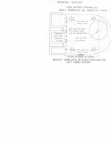
ININST.1002(G) Page 16 of 16
Bottom Plan View, Head Jamb (looking up)
Showing Upper Strike Mounting Holes
3/4" dia. cut
strike opening
for bottom latch
thru threshold
29/32"
Blade
stop
bottom latch
Top Plan View, Rod Latch
Showing Strike Cutout in Threshold
for Round Latch
Detail A
(for cylinder)
3/64"
Door clear opening
11/16"
11/32"
21/32"
11/16"
of top latch
#29 (0.136")
drill,
#8-32 tap,
4 holes
Blade
stop
Door
height
7/16"
1-3/8"
1-3/8"
1/8"
1-1/4"
7/8"
Cutout on inside
face only
1/4" radius
Hinge stile
Lock stile
15/64" dia.
drill thru, c'sink
with 5/16" dia.
tool, 2 holes,
for cylinder;
see Detail A
13/32"
13/16"
#9 (0.196") drill, c'sink 82°
to 25/64" dia., 4 holes,
inside face only
7/16"
1-1/2"
1/4"
3"
1-1/2"
5/8"
1/2"
3/4" min.
1-3/8"
7/8"
Rod type latch
location
Bottom of door
Face of
door blade
stop
5/16"
9/16" dia. ream
for cylinder only
1-3/16" dia. hole,
outside face only,
for cylinder only
11/16"
3/8"
3/4"
See Note D
#7 (0.201")
drill thru,
1/4-20 tap,
4 holes
With Standard
Rods and Latches
1690 Touchbar
Concealed Vertical Rod
Panic Device
Door Preparation Template
Dimensions from face of door
blade stop to mounting hole
center lines 3/4" minimum.
NOTE D
!
1. All holes inside face only
except as noted.
2. All dimensions for 1-3/4"
thick, 1/8" wall doors.
Consult factory for others.
NOTES
!
LHR shown
RHR opposite
Pull side
Push side
Lock
stile
Hinge
stile
5/16" dia.
x 82°
countersink
41-5/16" to
bottom of
door;
dimension C
for setting
rod lengths
9/16" 3/8"
3/4"
Hex Bottom Bolt Mounting Location
#9 (0.196") drill,
c'sink 82° to 25/64"
dia., 2 holes,
inside face only
/