KitchenAid 740-0781 Owner's manual
- Category
- Barbecues & grills
- Type
- Owner's manual

KitchenAid ®
FREESTANDING OUTDOOR GRILL
For questions about features, operation/performance, parts, accessories or service, call: 1-877-373-2301
or visit our website at www.Kitchenaidgrills.com
P
ASADOR AUTONOMO PARA EXTERIOR
Para consultas respecto a caracteristicas, funcionamiento, rendimiento, piezas, accesorJos o servJcJot@cnJco, Ilame al: 1-877-373-2301
o vJsJtenuestro sJtio de Jnternet en www.Kitchenaidgrills.com
COMFFOIR POUR GRIL D'EXTERIEUR
AUTOPORTANT
............. ,:_ ....... _ o
Pour des questions apropos des caract@rJstiques, du fonctionnemenVrendement, des pJ@ces,des accessoJres ou du service,
composer le : 1-877-373-2301
ou vJsJtez notre site web www.Kitchenaidgrills.com
Table of Contents/Jndice/Table des matieres .................................................................. 2
740/750-0781
19000391 A0

TABLE OF CONTENTS
OUTDOOR GRILL SAFETY ................................................................. 3
INSTALLATION REQUIREMENTS .................................................... 5
Tools and Parts ........................................................................................ 5
Location Requirements ............................................................................ 5
Product Dimensions ................................................................................. 6
Built-In Outdoor Grill Enclosure ............................................................ 6
Cabinet Cutout Dimensions .................................................................... 7
Gas Supply Requirements ....................................................................... 8
Gas Connection Requirements ................................................................ 9
REPLACEMENT PARTS ..................................................................... 10
INSTALLATION INSTRUCTIONS .................................................... 12
Unpack Grill .......................................................................................... 12
Install Grill ............................................................................................. 12
Make Gas Connection ........................................................................... 14
GAS CONVERSIONS ............................................................................ 15
Check and Adjust the Burners ............................................................... 18
OUTDOOR GRILL USE ....................................................................... 20
Using Your Outdoor Grill ..................................................................... 20
Using Your Infrared Searing Burner .................................................... 22
Using Your Rotisserie Burner ............................................................... 22
Rotisserie Cooking Tips ........................................................................ 23
TIPS FOR OUTDOOR GRILLING ..................................................... 24
Cooking Methods .................................................................................. 24
Grilling Chart ........................................................................................ 25
OUTDOOR GRILL CARE ................................................................... 27
Replacing the Igniter Battery ................................................................ 27
General Cleaning ................................................................................... 27
TROUBLESHOOTING ......................................................................... 29
ASSISTANCE .......................................................................................... 29
Accessories ............................................................................................ 29
WARRANTY ........................................................................................... 30
NrDICE
SEGURIDAD DEL ASADOR PARA EXTERIORES ....................... 33
REQUISITOS DE INSTALACI6N ...................................................... 35
Herramientas y piezas ............................................................................ 35
Reqnisitos de ubicaci6n ......................................................................... 35
Medidas del producto ............................................................................ 36
Recinto del asador empotrado para exteriores ...................................... 36
Dimensiones del corte del armario ........................................................ 37
Reqnisitos del suministro de gas ........................................................... 38
Reqnisitos para la conexi6n de gas ....................................................... 39
PIEZAS DE REPUESTO ....................................................................... 41
INSTRUCCIONES DE INSTALACI6N ............................................. 44
Desempaque el asador ........................................................................... 44
Instalacidn del asador ............................................................................ 45
Conexi6n del suministro de gas ............................................................ 45
CONVERSIONES DE GAS ................................................................... 46
Revise y regule los quemadores ............................................................ 50
USO DEL ASADOR PARA EXTERIORES ....................................... 52
C6mo usar el asador para exteriores ..................................................... 52
Uso del quemador infrarrqjo para dorado rfipido ................................. 54
Uso del quemador del rostizador .......................................................... 54
Consejos para la cocci6n con el rostizador ........................................... 55
CONSEJOS PARA ASAR AL AIRE LIBRE ...................................... 56
Mdtodos de coccidn ............................................................................... 57
Cuadro para asar .................................................................................... 57
CUIDADO DEL ASADOR PA1L_ EXTERIORES ............................ 60
Cdmo reemplazar la bateria del encendedor ....................................... 60
Limpieza general ................................................................................... 60
SOLUCI6N DE PROBLEMAS ............................................................ 62
ASISTENCIA .......................................................................................... 62
Accesorios ............................................................................................. 62
GA1L_NTL_ ............................................................................................. 63
TABLE DES MATIERES
SI_CURITI_ DU GRIL D'EXT6RIEUR ............................................... 63
EXIGENCES D'INSTALLATION ....................................................... 65
()utils et pi_ces ....................................................................................... 65
Exigences d'emplacement ..................................................................... 65
Dimensions du produit .......................................................................... 66
Enceinte du gril d'extdrieur encastrd ..................................................... 66
Dimensions de l'ouverture fl ddcouper dans le placard ......................... 67
Spdcifications de l'alimentation en gaz ................................................. 69
Exigences concemant le raccordement au gaz ..................................... 69
PI6CES DE RECHANGE ...................................................................... 73
INSTRUCTIONS D'INSTALLATION ................................................ 75
Ddballage du gril ................................................................................... 75
Installation du gril .................................................................................. 75
Raccordement au gaz ............................................................................. 77
CONVERSIONS POUR CI-L_NGEMENT DE GAZ ......................... 78
Contr61e et rdglage des brfileurs ............................................................ 82
UTILISATION DU GRIL D'EXT6RIEUR ........................................ 83
Utilisation du gril d'extdrieur ................................................................ 83
Utilisation du brfileur infrarouge fl r6tissage ........................................ 85
Utilisation du brfileur de toumebroche ................................................. 85
Conseils de cuisson fl l'aide du tournebroche ....................................... 86
CONSEILS POUR L'UTILISATION DU GRIL D'EXT6RIEUR. 87
Mdthodes de cuisson ............................................................................. 88
Tableau de cuisson au gril ..................................................................... 88
ENTRETIEN DU GRIL D'EXT6RIEUR ........................................... 91
Remplacement de la pile de l'allumeur ................................................ 91
Nettoyage gdndral .................................................................................. 91
D6PANNAGE ......................................................................................... 93
ASSISTANCE .......................................................................................... 93
Accessoires ............................................................................................ 93
GARANTIE ............................................................................................. 94
2

OUTDOOR GRILL SAFETY
Your safety and the safety of others are very important.
We have provided many important safety messages in this manual and on your appliance. Always read and obey all safety
messages.
This is the safety alert symbol.
This symbol alerts you to potential hazards that can kill or hurt you and others.
All safety messages will follow the safety alert symbol and either the word "DANGER" or "WARNING."
These words mean:
You can be killed or seriously injured if you don't immediately
follow instructions.
You can be killed or seriously injured if you don't follow
instructions.
All safety messages will tell you what the potential hazard is, tell you how to reduce the chance of injury, and tell you what can
happen if the instructions are not followed.
_, DANGER
If you smell gas:
1. Shut off gas to the appliance.
2. Extinguish any open flame.
3. Open lid.
4. If odor continues, keep away from the
appliance and immediately call your
gas supplier or your fire department.
WARNING
1. Do not store or use gasoline or other
flammable liquids or vapors in the
vicinity of this or any other appliance.
2. An LP cylinder not connected for use
shall not be stored in the vicinity of
this or any other appliance.
S_t_ _ CaHf_nia Propo_tien 65 W_nir_s:
WARNING:This p_c_ con_ms one onmore chem_a_s know_ to the State of Ca_iifocniato cause canc:e_°
WARNING:This p_uct centares one onmore _em_a_s known to the State of C_ifomia to cause bi_h defects or ot_heF
_odu_ive h_m,
In the State of Massachusetts, the following installation instructions apply:
[] Installations and repairs must be performed by a qualified or licensed contractor, plumber, or gasfitter qualified or licensed by
the State of Massachusetts.
[] If using a ball valve, it shall be a T-handle type.
[] A flexible gas connector, when used, must not exceed 3 feet.
|M| ORTANT: This grill is manufactured for outdoor use only. [:orgrills that are to be used at elevations above 2000 ft (609.6 m) orifice conversion
is required. See "Gas Supply Requirements" section. It is the responsibility of the installer to comply with the minimum installation clearances
specified on the model/serial rating plate. The model/serial rating plate for built-in models can be found on the right-hand side of the grill.

iMPORTANT SAFETY iNSTRUCTiONS
WARNING: To reduce the risk of fire, electrical shock,
injury to persons, or damage when using the outdoor cooking
gas appliance, follow basic precautions, including the
following:
[] Do not install portable or built-in outdoor cooking gas
appliances in or on a recreational vehicle, portable trailer,
boat or in any other moving installation.
[] Always maintain minimum clearances from combustible
construction, see "Location Requirements" section.
[] The outdoor cooking gas appliance shall not be located
under overhead unprotected combustible construction.
[] This outdoor cooking gas appliance shall be used only
outdoors and shall not be used in a building, garage, or any
other enclosed area.
[] Keep any electrical supply cord and fuel supply hose away
from any heated surfaces.
[] Keep outdoor cooking gas appliance area clear and free
from combustible materials, gasoline and other flammable
vapors and liquids.
[] Do not obstruct the flow of combustion and ventilation air.
Keep the ventilation openings of the cylinder enclosure free
and clear from debris.
[] Open the cabinet door and inspect the gas cylinder supply
hose before each use of the outdoor cooking gas
appliance. If the hose shows excessive abrasion or wear,
or is cut, it MUST be replaced before using the outdoor
cooking gas appliance. Contact your dealer and use only
replacement hoses specified for use with the outdoor
cooking gas appliance.
Visually check the burner flames.
They should be blue. Slight
yellow tipping is normal for LP
gas. The flames should be
approximately 1" (2.5 cm) high.
Check and clean burner/venturi tube for insects and insect
nest. A clogged tube can lead to fire under the outdoor
cooking gas appliance.
SAVE THESE
[] The LP gas supply cylinder to be used must be:
- constructed and marked in accordance with the
Specification for LP Gas Cylinders of the U.S. Department
of Transportation (DOT) or the National Standard of
Canada, CAN/CSA-B339, Cylinders, Spheres, and Tubes
for Transportation of Dangerous Goods; and Commission.
- provided with a listed overfilling prevention device.
- provided with a cylinder connection device compatible
with the connection for outdoor cooking gas appliances.
[] Always check connections for leaks each time you connect
and disconnect the LP gas supply cylinder. See
"Installation Instructions" section.
[] When the outdoor cooking gas appliance is not in use, the
gas must be turned off at the supply cylinder.
[] Storage of an outdoor cooking gas appliance indoors is
permissible only if the cylinder is disconnected and
removed from the outdoor cooking gas appliance.
[] Cylinders must be stored outdoors and out of the reach of
children and must not be stored in a building, garage, or
any other enclosed area.
[] The pressure regulator and hose assembly supplied with
the outdoor cooking gas appliance must be used. A
replacement pressure regulator and hose assembly
specific to your model is available from your outdoor
cooking gas appliance dealer.
[] Gas cylinder must include a collar to protect the cylinder
valve.
[] For appliances designed to use a CGA791 Connection:
Place a dust cap on cylinder valve outlet whenever the
cylinder is not in use. Only install the type of dust cap on
the cylinder valve outlet that is provided with the cylinder
valve. Other types of caps or plugs may result in leakage
of propane.
If the following information is not followed exactly, a fire
causing death or serious injury may occur.
[] Do not store a spare LP gas cylinder under or near this
outdoor cooking gas appliance.
[] Never fill the cylinder beyond 80 percent full.
INSTRUCTIONS
4

INSTALLATION REQUIREMENTS
Gather the required tools and parts before starting installation. Read and
follow the instructions provided with any tools listed here.
Tools Needed
• Tape measure
• Small, flat-blade screwdriver
• #2 and #3 Phillips screwdriver
• Level
• Wrench or pliers
• Pipe wrench
• Scissors or cutting pliers
(to remove tiedowns)
• Noncorrosive leak- detection
solution
Parts Supplied
• Gas pressure regulator/hose assembly set fbr 11" WCP LP gas.
• 1 - "AA" size alkaline battery
• 20 lb LP gas fuel tank tray
• 12 screws (fbr installing 20 lb LP gas fuel tank tray, 90 ° brass clamp/
Natural gas regulator clamp)
• Hardware packet
• 2 piece 90 ° brass clamp (fbr mounting 90 ° brass connector)
• Hex wrench (fbr loosening control knobs)
• Warming rack
Parts Needed
• 20 lb LP gas fuel tank
Parts Supplied for Conversion to Natural Gas
• Natural gas conversion kit (which includes):
• Natural gas regulator (marked "Natural Gas Regulator")
• 10 ft (3.0 m) PVC flexible gas supply hose with quick connector
• 6 mm nut driver
• Natural gas regulator clamp
• 2.05 mm Natural gas orifice for rotisserie/infrared burner
• 2.10 mm Natural gas orifice for infrared searing burner
Parts Needed for Conversion to Natural Gas
• Gas line shutoff valve
• V2" male pipe thread nipple for connection to pressure regulator.
• LP gas-resistant pipe-joint compound
• CSA design-certified outdoor flexible stainless steel appliance
connector (4-5 ft [ 1.2-1.5 m]) or rigid gas supply line as needed.
Explosion Hazard
Do not store fuel tank in a garage or indoors.
Do not store grill with fuel tank in a garage or indoors.
Failure to follow these instructions can result in death,
explosion, or fire.
Fire Hazard
Do not use grill near combustible materials.
Do not store combustible materials near grill.
Doing so can result in death or fire.
Select a location that provides minimum exposure to wind and traffic
paths. The location should be away from strong draft areas.
Do not obstruct flow of combustion and ventilation air.
Clearance to combustible construction tbr outdoor grills:
• A minimum of 24" (58.0 cm) must be maintained between the front
of the grill hood, sides and back of the grill and any combustible
construction.
• A 24" (58.0 cm) minimum clearance must also be maintained below
the cooking surface and any combustible construction.
Rotisserie (accessory)*
If you equip your grill with a rotisserie, a 6" (15.2 cm) minimum
clearance is needed tbr the rotisserie motor.
A grounded, 3 prong outlet located to the left of the grill is required.
*See "Assistance" section to order.

iii:_'_i>_iiiii_•:_:_ii_;:_iiiliiiiii?_i_i,ili_ii<!_ii!_;ii_ili_ii,i,i_!_; !ii::_i_•:_:_iii!,ii>iiii_i_i_i_•_i_,iiiil),_•i:?_iiii_iiiii,_ii_,_ii_,_iii¸_(i_iii_'i!!i_ii:!)_,_;:!_i:i_,!,!!_ii_•i:_ii_i_ii%_
Fire Hazard
Do not install grill on or near combustible materials.
Doing so can result in death or fire.
The enclosure for the built-in outdoor grill is to be a minimum of 11"
(28.0 cm) high x 23" (58.4 cm) deep x 36" (91.4 cm) wide.
This built-in outdoor grill is only for installation in a built-in enclosure
constructed only of noncombustible materials. Non-combustible
materials could be brick, firewall or steel• Do not use wood or other
combustible materials for built-in enclosure.
6

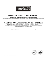
Theillustrationbelowincludescutoutdimensionsandminimumspacingrequirements.Theillustrationisforreference.Thedesignofyourcabinet
layoutcanbepersonalized,butthedimensionsforthecutoutsandminimumspacingmustbefollowed.
Centerorsupportsur[Scesmustbelevel.
Theinstallationofthisgrillmustcon_brmwithlocalcodesor,intheabsenceoflocalcodes,witheithertheNationalFuelGasCode,ANSIZ223.1/
NPFA54,NaturalGasandPropaneInstallationCode,CSAB149.1,orPropaneStorageandHandlingCode,B149.2.
Copiesofthestandardslistedmaybeobtainedfrom:
CSAInternational
8501EastPleasantValleyRd.
Cleveland,Ohio44131-5575
NOTE:Thegrilldropsintotheopeningandissupportedbyitssideflanges.Donotuseabottomsupport.
6" (I5.2crn)
4" (1Ocrn)
36. 5" (92.7crn)
Built-in Outdoor Grill Enclosure Ventilation Requirements
Any enclosure is to be ventilated by openings at both the top and lower
levels of the enclosure. The following in_brmation is the minimum for
proper ventilation of your island construction.
There should be a minimum of 1 7/8" (4.4 cm) of clearance from the
bottom of the main burner bowl assembly and the front wall of the
island for proper ventilation.
NOTE: There should be no solid sur[Sce underneath the firebox
portion of the grill.
A minimum of 3" (7.6 cm) is required between the back of the grill
and any noncombustible materials. A minimum of
24" (61.0 cm) is required between the back of the grill and any
combustible material.
The island must be vented in one of the 2 following ways:
A 90° or a 180° ventilation in the island to ensure that air flows
through the island at either 90 ° or 180°.
Any enclosure for built-in installation is to have at least one
ventilation opening on an exposed exterior side located within 2V:"
(6.0 cm) of the top and is to be a minimum of
20 in.2(129.0 cm_). One ventilation opening within
1V:"(3.0 cm) of the bottom of the enclosure, and the bottom opening
is to be a minimum of 10 in) (64.5 cm_). All vent openings are to be
unobstructed. Every opening is to be a minimum of 1/8" (0.32 cm)
wide. 7

Toensurethatthegrilloperatesproperly,itisrecommendedthatthe
islandhaveventilationonall4sidesasshowninthefollowing
illustration.Theventilationholesshouldbeasdiagramedtoensure
adequateventilationforyourgrillandisland.
20 in.2(129.0 cm 2)rain.
ventilation both sides
f/2"
10 in. 2 (64.5 crn2) vain.
ventilation both sides
"--,,2_/;' (6.0 cm) max.
= Proper ventilation is a required based on the above mentioned
specifications for your grill to operate properly.
LP Gas
LP Gas Pressure Regulator/Hose Assembly Location
Measurements shown are for attaching the LP gas pressure regulator/
hose assembly to the enclosure.
Natural Gas Conversion
Natural Gas Pressure Regulator Location
Measurements shown are for attaching the Natural gas pressure regulator
to the enclosure.
\
\
\
\
\
10"(25 4cm)
i ........ H JJiiiii ........ i
Explosion Hazard
Use a new CSA International approved "outdoor"
gas supply line.
Install shut-off valve.
Securely tighten all gas connections.
If connected to LP, have a qualified person make sure
gas pressure does not exceed 14" (36 cm) water
column.
Examples of a qualified person include:
licensed heating personnel,
authorized gas company personnel, and
authorized service personnel.
Failure to do so can result in death, explosion, or fire.
Observe all governing codes and ordinances.
IMPORTANT: This installation must conlbrm with all local codes and
ordinances. In the absence of local codes, installation must conlbrm with
American National Standard, National Fuel Gas Code ANSI Z223.1 -
latest edition or CAN/CGA B 149.1 - latest edition.
IMPORTANT: Grill must be connected to a regulated gas supply.
8

Refertothemodel/serialratingplateforinibrmationonthetype
ofgasthatcanbeused.Ifthisinibrmationdoesnotagreewith
thetypeofgasavailable,checkwithyourlocalgassupplier.
Gas Conversion:
No attempt shall be made to convert the grill from the gas
specified on the model/serial rating plate for use with a different
gas type without consulting the serving gas supplier. The
conversion kit supplied with the grill must be used. See "Gas
Conversions" section.
Gas Pressure Regulator
The gas pressure regulator supplied with this grill must be used. The
inlet (supply) pressure to the regulator should be as follows for proper
operation:
LP Gas:
Operating pressure: 11" (27.9 cm) WCP
Inlet (supply) pressure: 11" to 14" (27.9 cm to 35.5 cm) WCP
Natural Gas:
Operating pressure: 4" (10.2 cm) WCP
Inlet (supply) pressure: 7" to 14" (17.8 cm to 35.5 cm) WCP
maximum.
Contact local gas supplier if you are not sure about the inlet (supply)
pressure.
r
Burner Requirements for High Altitude
Input ratings shown on the model/serial rating plate are for elevations up
to 2,000 ft (609.6 m).
For elevations above 2,000 ft (609.6 m), ratings are reduced at a rate of
4% for each 1,000 ft (304.8 m) above sea level. Orifice conversion is
required. See "Assistance" section to order.
Gas Supply Line Pressure Testing
Testing above ½ psi (3.5 kPa) or 14" (35.5 cm) WCP (gauge):
The grill and its individual shutoff valve must be disconnected from the
gas supply piping system during any pressure testing of that system at
test pressures greater than V2psig (3.5 kPa).
Testing below ½ psi (3.5 kPa) or 14" (35.5 era) WCP (gauge) or
lower:
The grill must be isolated from the gas supply piping system by closing
its individual manual shutoff valve during any pressure testing of the gas
supply piping system at test pressures equal to or less than V2psig (3.5
kPa).
This grill is equipped for use with a 20 lb LP gas fuel tank (fuel tank not
supplied). A gas pressure regulator/hose assembly is supplied.
Any brand of 20 lb LP gas fuel tank is acceptable for use with the grill
provided they are compatible with the grill's retenion means (tank tray
included).
The grill is also design-certified by CSA International for local LP gas
supply or lbr Natural gas with appropriate conversion.
20 lb LP Gas Fuel Tank
The 20 lb LP gas fuel tank must be mounted and secured.
1. Open cabinet doors.
2. Loosen the tank tray locking screw.
3. Place the 20 lb LP gas fuel tank bottom collar into the mounting hole
in the tank tray.
4. Tighten the locking screw against the bottom collar of the 20 lb LP
gas fuel tank to secure.
/
A
A. Locking screw
B. Tank tray
C 20 lb LP gasf!¢el tank tray
LP Gas Conversion Using a Local LP Gas Supply
If you want to convert to local LP gas supply, contact your local gas
company lbr specific instructions.
Natural Gas Conversion
Conversion must be made by a qualified gas technician. The qualified
Natural gas technician shall provide the Natural gas supply to the
selected grill location in accordance with the National Fuel Gas Code
ANSI Z223.1/NFPA 54 - latest edition, and local codes. For conversion
to Natural gas, the Natural gas conversion kit supplied with the grill
must be used. See the "Gas Conversions" section.
IMPORTANT: The gas installation must conibrm with local codes, or
in the absence of local codes, with the National Fuel Gas Code, ANSI
Z223.1/NFPA 54 - latest edition.
The supply line shall be equipped with an approved shutoffvalve. This
valve should be located in the same area as the grill and should be in a
location that allows ease of opening and closing. Do not block access to
the shutoff valve. The valve is for turning on or shutting off gas to the
grill.
/3
\
A. Gas supply line
B. Shutoff valve "open" position
C. To grill
A
A. Gas pressure tKqulator/hose assembly

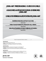
REPLACEMENT PARTS
01
3i
10

Part Part (description) Warran_ Quantity
Number Coverage
01 Main lid 3 1
02 Main lid screw with screw 3 2
cover
03 Temperature gauge housing 3 1
04 Temperature gauge 1 1
05 Main lid handle seat with 1 1
heat insulating spacer, left
06 Main lid handle seat with 1 1
heat insulating spacer, right
07 Main lid handle tube 3 1
08 Rotisserie burner igniter 1 1
wire
09 Rear baffle 3 1
10 Rotisserie heat shield 3 1
11 Rotisserie burner 1 1
12 Rotisserie burner igniter 3 2
bracket
13 Rotisserie burner flex gas 1 1
line
14 Rotisserie orifice with brass 1 1
elbow
15 Main lid bracket, left 3 1
16 Main lid bracket, right 3 1
17 Flange, left 3 1
18 Flange, right 3 1
19 Main burner flex gas clamp 3 1
20 90 ° brass adaptor 1 1
21 Front baffle 1 1
22 Main burner flex gas line 1 1
23 Main manifold 1 1
24 Main gas valve 1 4
25 Regulator, LP 1 1
26 Igniter.junction wire 1 1
27 Sear gas valve 1 1
28 Rotisserie gas valve 1 1
29 Electronic igniter module 1 1
30 Logo 1 1
31 Main control panel 3 1
32 Control knob, main burner 1 5
33 Control knob bezel,main 1 5
burner
Part Part (description) Warranty Quanti_
Number Coverage
Control knob bezel, rotisserie 1 1
burner
35 Control knob, rotisserie 1 1
burner
36 Trim piece, rear 3 1
37 Sear burner 1 1
38 Sear burner igniter wire 1 1
39 Main burner igniter wire, A 1 1
40 Main burner igniter wire, B 1 1
41 Main burner igniter wire,C 1 1
42 Main burner igniter wire,D 1 1
43 Main burner 10 4
44 Flame tamer 3 4
45 Cooking grid with hole 3 3
46 Warming rack 3 1
47 Burner pin assembly 1 4
48 Tank tray 3 1
49 Tank tray bolt 1 1
50 90° clamp,right 3 1
51 90° clamp,left 3 1
52 Preassembly hardware pack 1 1
53 Regulator with brass 1 1
connector, Natural gas
54 Natural gas regulator clamp 3 1
55 Nut &iver 1 1
56 Grease cup 3 1
57 10 ft (3.0 m) PVC flexible 1 1
gas supply hose with quick
connector
58 Lighting rod 1 1
59 Trim piece, front 3 1
60 Electronic igniter module 1 1
heat shield panel
61 Main burner bowl assembly Non-
replaceable 1
Natural gas orifice kit 1 1
34
11

INSTALLATION INSTRUCTIONS
Excessive Weight Hazard
Use two or more people to move and install grill.
Failure to do so can result in back or other injury.
Unpack Grill
1. Remove all packaging materials and remove grill from the shipping
base.
2. Move grill close to desired outdoor location•
3. ()pen the grill hood.
4. Using an utility knife to cut yellow straps and packing tape to open
box from top and remove the boxes•
5. Remove the warming shelf and grill grates from inside the grill and
remove the package inside the firebox•
6. Remove foam block and wrap from inside the grill•
Install 20 lb LP Gas Fuel Tank Tray
The tank tray should be secured to a fixed location that can be easily
accessed and will allow the gas pressure regulator/hose assembly to
connect to the 20 lb LP gas fuel tank without kinking or putting strain on
the gas pressure regulator/hose assembly•
1. Place the tank tray in a location that can be secured using
4 screws (supplied) through the predrilled holes•
2. Use 4 screws to secure the tank tray. The typical location for a 20 lb
LP gas fuel tank is within the enclosure where the tank ban be turned
on and off easily•
A
\\
\
\,
,\
J
J
/
7. Replace the grill grates•
8. Place warming shelf on brackets as shown.
B
A
A. Warming rack brackets
B. Warming rack
9. Dispose of/recycle all packaging material•
12

Place grill into outdoor enclosure, but leave enough room in the back to
connect to the gas supply.
Grease Cup Bracket Installation
1. Loosen and remove the 4 screws preassembled on the grease
cup bracket.
LP Gas Installation
1.
Cheek that the LP gas pressure regulator/hose assembly is
positioned under the grill (as shown in the following illustration)
and is not pinched or kinked.
Use 2 screws and the 1-piece 90° clamp mounting bracket provided
to attach the 90° brass connector to the back of the enclosure. The
/////
//
/.
brass connector is located between the flexible gas hose and the LP 2. Attach the left and right grease cup bracket on firebox bottom
gas pressure/hose assembly, panel under side, align screw holes, insert 4 screws which moved
from step 1 into these screw holes. Screws lock from firebox
bottom panel under side.
B
A
A. 2 screws
B. one piece brass clamp mounting bracke
3. Tighten these 4 screws.
13

NOTE: If grill is to be converted to Natural gas, follow instructions in
the "Gas Conversions" section.
20 lb LP Gas Fuel Tank
Fire Hazard
Do not use grill near combustible materials.
Do not store combustible materials near grill.
Doing so can result in death or fire.
Explosion Hazard
Use a new CSA International approved "outdoor"
gas supply line.
install shut=off vane.
Securely tighten ail gas connections.
if connected to LP, have a qualified person make sure
gas pressure does not exceed 14" (36 cm) water
column.
Examples of a qualified person include:
licensed heating personnel,
authorized gas company personnel, and
authorized service personnel.
Failure to do so can result in death, explosion, or fire.
IMPORTANT: A 20 lb LP gas fuel tank must be purchased separately.
IMPORTANT: The gas pressure regulator/hose assembly supplied must
be used. Replacement gas pressure regulator/hose assembly specific to
your model, is available from your outdoor grill dealer.
To Install the 20 lb LP Gas Fuel Tank:
1. Install the 20 lb LP gas fuel tank into the compartment below the
grill.
2. Tighten the locking screw against the bottom collar of the
20 lb LP gas fuel tank to secure.
To Connect the 20 lb LP Gas Fuel Tank:
1. Check that the 20 lb LP gas fuel tank is in the "Oft "' position. If not,
turn the valve clockwise until it stops.
2. Check that the 20 lb LP gas fuel tank valve has the proper type-1
external male thread connections per ANSI Z21.81.
3. Check that the burner control knobs are in the "Oft "' position.
4. Remove any debris and inspect the valve connections, port, and gas
pressure regulator/hose assembly for damage.
5. Using your hand, turn the gas pressure regulator/hose assembly
clockwise to connect to the 20 lb LP gas fuel tank as shown.
Hand tighten only. Use of a wrench could damage the quick
coupling nut.
A. Gas pressure regulator/hose assembly
B. 20 lb LP gas fitel tank
6. ()pen the tank valve fully by turning the valve counterclockwise.
Wait a few minutes for gas to move through the gas line.
7. Before lighting the grill, test all connections by brushing on an
approved noncorrosive leak-detection solution. Bubbles will show a
leak.
8. If a leak is tbund, turn the tank valve off and do not use the grill.
Contact a qualified gas technician to make repairs.
9. The igniter battery is not factory installed. A "AA" size alkaline
battery is located in the accessory box on the grill grate. Install
battery at this time following the instructions in "Replacing the
Igniter Battery" section.
10. Go to "Check and Adjust the Burners" section.
14

GAS CONVERSIONS
Gas Connection to Natural Gas
5. Use an adjustable wrench to remove the LP gas pressure regulator/
hose assembly from the 90° brass adapter.
Explosion Hazard
Use a new CSA International approved "outdoor"
gas supply line.
install a shut-off valve.
Securely tighten ail gas connections.
Failure to do so can result in death, explosion, or fire.
This installation must conform with local codes and ordinances. In the
absence of local codes, installations must contbrm with either the
National Fuel Gas Code ANSI Z223.1 - latest edition, or CAN/CGA-
B 149.1 Natural Gas and Propane installation code.
Copies of the standards listed above may be obtained from:
CSA International
8501 East Pleasant Valley Rd.
Cleveland, Ohio 44131-5575
National Fire Protection Association
One Batterymarch Park
Quincy, Massachusetts 02269
IMPORTANT: The Natural gas Conversion Kit supplied with this grill
must be used.
1. Turn off all burner control valves.
2. Turn off the main gas supply valve.
3. Disconnect 20 lb LP gas fuel tank (if present) and remove the 20 lb
LP gas fuel tank from the grill cabinet.
4. Use a Phillips screwdriver to remove the one-piece brass clamp
mounting bracket from the cabinet wall.
\
'\\\\\
\\
B
A
.4. 2 screws
B. one-piece brass clamp mounting bracket
A
C
.4. Flexible gas hos<#'om grill
B. 90 ° brass adapter
C. LP gas pressure regulator/hose assembly
6. Install the Natural gas pressure regulator onto the flexible gas hose
from the grill.
7. Check that the Natural gas pressure regulator is positioned under the
grill (as shown in the following illustration) and is not pinched or
kinked.
8. Use 4 screws to attach the Natural gas pressure regulator to the back
of the enclosure.
A
B
.4. Natural gas pressw'e regulator
B. Four 5/32"x 10 mm truss head screws
1. Make gas connections.
A combination of pipe fittings must be used to connect the grill to
the existing gas line.
• The 10 ft (3.0 m) PVC flexible gas supply hose design-certified
by CSA must be used.
• Pipe-joint compounds suitable for use with Natural gas must be
used. Do not use Teflon "_*tape.
2. Connect the brass connector on one end of the 10 ft (3.0 m) PVC
flexible gas supply hose (supplied) to the Natural gas pressure
regulator (A).
t_r<:TEFLON is a registered trademark of E.I. Dn Pont De Nemonrs and Company.
15

3.
Connect the quick connector on the other end of the
10' (3.0 m) PVC flexible gas supply hose to the rigid Natural gas
supply pipe (B).
A
B
A. Brass connector
B. Quick connector
Change Grill Main Burner Valve Orifices
1. Remove the grates and flame tamers.
2. Remove the screw and clip that hold the burner in place. Set the
screw and clip aside. Remove the burner from the grill by lifting the
burner out.
3. Use a 6 mm socket madwrench or 6 mm nut driver to remove the
brass orifice from the end of gas valve. The main burner NG orifice is
located behind the LP orifice, so no additional orifice needs to be
installed.
A. JJain burner orifice
4. Reinsert the burner and reattach using the screw and the clip
previously removed. Repeat the procedure for each main burner.
5. Position the igniters so they are ¼" (6.0 mm) away from each burner.
Change the Rotisserie/Infrared Burner Orifice
1. Using a Phillips screwdriver, unscrew the 2 screws and remove the
rotisserie/infi'ared burner wind baffle.
16
A. Wind baffle

2_
Remove the access cover at the back of the grill by removing the 6
screws at the back of firebox.
\
\
5_
Take out the orifice support, and then use a 6 mm socket and wrench
or 6 mm nut driver to remove the LP orifice at the end of the supply
pipe. Replace with Natural gas orifice.
A
\
\
\
3_
A
_. _CCeSS CO12eF
Using a Phillips screwdriver, remove the screw holding the spider
guard to the burner.
%
\
\
\
4. Use 24 mm wrench to remove the orifice nut.
A
A. Orij?ce nut
A. Orificesupport
B. Orifice
6. Reinstall the spider guard, access cover, and wind baffle.
Change the Infrared Searing Main Burner Orifices
1. Remove the screw securing the inii'ared searing main burner igniter
and remove the igniter from the searing burner.
2_
_.SC'FeW
A
Remove the infrared searing main burner cover screws. Set the
screws and cover aside.
A
_. 2 SCYeWS
17

3. Removetheinfraredsearingmainburnerfromfirebox.
4_ Use a 6 mm socket and wrench or 6 mm nut driver to remove the LP
gas orifice on the end of valve. Replace with Natural gas orifice.
o rifi ce --
g. Reinstall infrared searing main burner. Make sure that the igniter is
out of the way to allow proper positioning of burner. Use a Phillips
screwdriver to attach the mounting screws.
6. Use a Phillips screwdriver to reattach the igniter and infrared searing
main burner plate.
7. Reinstall infrared searing main burner cover. Use a Phillips
screwdriver to attach mounting screws.
8. Open the manual shutoff valve in the gas supply line. The valve is
open when the handle is parallel to the gas pipe.
Record Conversion
The model/serial number plate is located on the right-hand side of the
grill. With a permanent marker, check the box next to "Natural gas" and
mark through "LR"
In the last page of the Use and Care Guide, write "Converted to Natural
Gas." Also record the conversion date and the technician/company that
performed the conversion.
NOTE: Place the LP gas parts in plastic parts bag for future use and
keep with package containing the literature.
The burners are tested and factory-set for most efficient operation.
However, variations in gas supply and other conditions may make minor
adjustments to air shutter or low flame setting necessary.
It is recommended that a qualified person make burner adjustments.
NOTE: The rotisserie burner cannot be adjusted.
Checking and adjusting the grill burner flames requires removing the
grates and flame tamers.
Burner Flame Characteristics
The flames of the grill burners and side burners (on some models) should
be blue and stable with no excessive noise or lifting (LP gas flames will
have a slightly yellow tip). A yellow flame indicates not enough air. If
flame is noisy or lifts away from the burner, there is too much air. Some
yellow tips on flames when the burner is set to HI setting are acceptable
as long as no carbon or soot deposits appear.
Check that burners are not blocked by dirt, debris, insect nests, etc., and
clean as necessary. If they are clean, adjust air shutters as needed.
IMPORTANT: Before adjusting air shutters, let burners cool
completely.
To Adjust:
1. Light grill using information in the "Outdoor Grill Use" section.
2. Observe flame to determine which burners need adjustment and how
the flame is acting.
3. Tuna off the valve and wait until grill and burners cool completely.
4. Remove grill grates and flame tamers.
A. Closed valve
B. Open valve
9. Test all connections by brushing on an approved noncorrosive leak-
detection solution. Bubbles will show a leak. Correct any lea&
found.
1O. The igniter battery is not factory installed. A "AA" size alkaline
battery is located in the accessory box on the grill grate. Install
battery at this time following the instructions in "Replacing the
Igniter Battery" section.
11. Go to "Check and Adjust the Burners" section.
18

5.
6.
7.
8.
Remove the screw and clip that hold the burner in place. Remove
gas burner from the grill.
A
A. Clip
If flame is yellow (not enough air), turn air shutter adjustment screw
counterclockwise.
If flame is noisy or lifts away from burner (too much air), turn air
shutter adjustment screw clockwise.
A. Air shutter adjustment screw
Adjustment should be made clockwise or counterclockwise from 1/
8" (3.2 mm) to 1/4" (6.4 mm).
Replace gas burner, flame tamers and grates.
Light grill using inIbrmation in the "Outdoor Grill Use" section. See
"Burner Flame Characteristics."
Low Flame Adjustment
If flame goes out on the "LO" setting, the low flame setting must be
adjusted.
1. Turn off the valve and wait until grill and burners are cool.
2. Remove grill grates and flame tamers.
3. Light grill using information in the "Outdoor Grill Use" section.
4. Turn burner to its lowest setting and remove knob.
5. Hold valve stem with pliers and insert a small flat-blade screwdriver
into the shaft.
6. Watch the flame and slowly turn the screwdriver counterclockwise.
7. Adjust flame to minimum stable flame.
C
A. Vah,e stem
B. SmallJlat-blade screudriver
C. Pliers'
8. Replace the control knob and turn off the burner.
9. Repeat steps 3 through 8 for each burner if needed.
10. Replace the flame tamers and grates after the burners have cooled.
19

OUTDOOR GRILL USE
This manual covers several different models. The grill you have purchased may have some or all of the features listed. The locations and appearances
of the features shown here may not match those of your model,
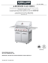
Control Panel
I
A B C D E F
A. Left grill burner control knob
B. Left center grill burner control knob
C. Right center grill burner control knob
D. Right grill burner control knob
E. Rotisserie burner control knob
F Infrared searing burner control knob
Explosion Hazard
Do not store fuel tank in a garage or indoors.
Do not store grill with fuel tank in a garage or indoors.
Failure to follow these instructions can result in death,
explosion, or fire.
Fire Hazard
Do not use grill near combustible materials.
Do not store combustible materials near grill.
Doing so can result in death or fire.
Food Poisoning Hazard
Do not let food sit for more than one hour before or
after cooking.
Doing so can result in food poisoning or sickness.
Inspect the LP Gas Fuel Tank Supply Hose
Inspect the gas wessure regulator/hose assembly betbre each use.
1. Inspect the gas pressure regulator/hose assembly for cuts, abrasions,
or excessive wear.
2. If necessary, replace the gas pressure regulator/hose assembly before
using the grill.
Contact the dealer and use only replacement hoses specified for use
with the grill.
A
A. Gas pressure re_dator/hose assembly
2O
Page is loading ...
Page is loading ...
Page is loading ...
Page is loading ...
Page is loading ...
Page is loading ...
Page is loading ...
Page is loading ...
Page is loading ...
Page is loading ...
Page is loading ...
-
 1
1
-
 2
2
-
 3
3
-
 4
4
-
 5
5
-
 6
6
-
 7
7
-
 8
8
-
 9
9
-
 10
10
-
 11
11
-
 12
12
-
 13
13
-
 14
14
-
 15
15
-
 16
16
-
 17
17
-
 18
18
-
 19
19
-
 20
20
-
 21
21
-
 22
22
-
 23
23
-
 24
24
-
 25
25
-
 26
26
-
 27
27
-
 28
28
-
 29
29
-
 30
30
-
 31
31


KitchenAid 740-0781 Owner's manual
- Category
- Barbecues & grills
- Type
- Owner's manual
Ask a question and I''ll find the answer in the document
Finding information in a document is now easier with AI
Related papers
-
KitchenAid 720-0893 Owner's manual
-
KitchenAid 730-0893G Operating instructions
-
-
-
KitchenAid 740-0781 Operating instructions
-
KitchenAid 720-0745B User guide
-
-
-
-
Other documents
-
Cuisinart CGL-330 Owner's manual
-
 Nexgrill 710-0002 Owner's manual
-
 Nexgrill 720-0709 Owner's manual
-
Jenn-Air 720-0720 Owner's manual
-
Jenn Air 720-0709 Owner's manual
-
Nex 720-0336C Owner's manual
-
 Jenn Air - Old 720-0720 Owner's manual
-
Amana AM26LP-P Owner's manual
-
 Kirkland Signature 720-1068 Operating instructions
-
Bull 114686 Operating instructions


