AVENTICS Series 616 Sentronic HD Installation guide
- Type
- Installation guide

IM14277/R02
GB
DE
Installation manual
Installationshandbuch
Sentronic
HD
Digital Pressure Regulator
Digitaler Druckregler
Series 616 / Baureihe 616

INSTALLATION
GB
2
Visit our website at Emerson.com/AVENTICS
CAUTION! Dangerous operating conditions may occur when using the programming interface on the valve as the valve may possibly
not react to the analog setpoint any more.
Provide for protection against uncontrolled movement of equipment when putting the valve into operation and before making any
modications to the valve settings.
NOTICE
The information in this manual is subject to change without notice.
In no event shall ASCO NUMATICS be liable for technical or editorial errors or omissions. Neither is any liability assumed for accidental
or consequential damages arising out of or in connection with the supply or use of the information contained herein.
THIS MANUAL CONTAINS INFORMATION PROTECTED BY COPYRIGHT. NO PART OF THIS DOCUMENT MAY BE PHOTOCOPIED OR
REPRODUCED IN ANY FORM OR MANNER WHATSOEVER WITHOUT PRIOR WRITTEN PERMISSION FROM ASCO NUMATICS.
COPYRIGHT © 2016 - ASCO NUMATICS - All rights reserved.
ESD
This product complies with the essential requirements of the EMC Directive 2014/30/EU and its amendments. It is CE-approved.
A separate Declaration of Conformity is available on request.
Please provide ordering code and serial numbers of products concerned.
We herewith declare that the version of the product described in this installation manual is intended to be incorporated into or assembled with
other machinery and that it must not be put into service until the machinery into which it is to be incorporated has been declared in conformity
with the provisions of Council Directive 2006/42/EC.
Handling, assembly and putting into service and all settings and adjustments must be done by qualied, authorised personnel only.
This product contains electronic components sensitive to
electrostatic discharge. An electrostatic discharge generated by a
person or object coming in contact with the electrical components
can damage or destroy the product.
To avoid the risk of electrostatic discharge, please observe the
handling precautions and recommendations contained in standard
EN 100015-1. Do not connect or disconnect the device while it is
energised.
CAUTION
OBSERVE PRECAUTIONS
FOR HANDLING
ELECTROSTATIC SENSITIVE DEVICES
!
CONTENTS / INHALT
English version _________________________________________________________ 2
1. Description _______________________________________________________________________________ 3
1.1 Catalogue number ____________________________________________________________________ 3
1.2 Operating elements ___________________________________________________________________ 4
1.3 Operating modes _____________________________________________________________________ 4
2. Electrical connection ________________________________________________________________________ 5
3. Analog setpoint - outlet pressure ______________________________________________________________ 6
4. Technical characteristics _____________________________________________________________________ 7
4.1 Fluid characteristics ___________________________________________________________________ 7
4.2 Specications ________________________________________________________________________ 7
6. Accessories _______________________________________________________________________________ 8
7. Maintenance and care _______________________________________________________________________ 9
8. Dimensions and weight _____________________________________________________________________ 9
Deutsche Version ______________________________________________________ 11

INSTALLATION
GB
3
Visit our website at Emerson.com/AVENTICS
1. DESCRIPTION
The Sentronic
HD
with integrated digital control loop combines the latest in pneumatics technology with in-
telligent electronics. The Sentronic
HD
series allows precise control of pressure, ow, force, velocity and dis-
placement or angle positions.
Cascaded control allows setting up complex control loops using the DaS-HD software (Data Acquisition Soft-
ware). Digital control offers many advantages during installation and start-up of the Sentronic
HD
valve and
extended possibilities to adapt it to various applications.
• Digital pressure control in a closed loop: An internal pressure sensor measures the inlet/outlet pressure.
The outlet pressure is adjusted in real time.
• The control parameters can be changed with the DaS software: This exibility allows the valve to be adapted
to the most various applications, and its response time, overshoot and precision to be optimised.
• After having set the optimum parameters, you can save them in a project le for your personal use or send
them to our Product Support for future serial production.
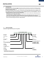
1.1 HOW TO ORDER
Sentronic
HD
- Digital electronic pressure regulator
15-DIGIT PRODUCT CODE
G 616 A C S I O I XXX PP
Pipe thread Pressure range
G = ISO 228 03 = 0...3 bar
06 = 0...6 bar
Product series
10 = 0...10 bar
V1 = -1 ... (+3 bar)
616
Revision letter Options
A = Initial A00 = Standard
Size Input 2 / Display with buttons
4 = G1/4 + pressure hold 0 = Standard NC + Display
5 = G1/4 + pressure release 2 = Analog IN 2 + Display
4 = Digital IN 2 + Display
Setpoint
6 = Frequency IN + Display *
0 = 0 - 10 V
1 = 0 - 20 mA
2 = 4 - 20 mA
3 = PWM - Frequency *
Feedback Output 2
0 = 0 - 10 V 0 = NC
1 = 0 - 20 mA 1 = Digital OUT
2 = 4 - 20 mA 2 = Analog Out 2
* If Setpoint PMW-Frequency is selected,
frequency input is not avaliable at IN 2

INSTALLATION
GB
4
Visit our website at Emerson.com/AVENTICS
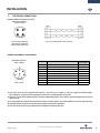
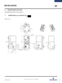
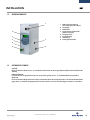
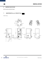
1.2 OPERATING ELEMENTS
1.3 OPERATING MODES
Shut-off:
If the setpoint falls below 0.5 %, the pilot valves is switched off and the valve is fully exhausted.
Overtemperature:
If the temperature of the internal control electronics exceeds 100°C, the operating mode is switched to AU-
TOSAFE.
Autosafe:
If the coil current exceeds a certain value, dependent on the mechanics, for more than 20 seconds, the output
current is limited to max. 70% to prevent the valve from overheating.
1 Power supply,
8-pin male connector M12
2 LC display
3 Control panel
4 Programming interface
(Ethernet TCP/IP)
5 Pressure supply
6 Pressure outlet
7 Exhaust
8 Ground connection M4 thread
1
2
7
6
3
5
8
4

INSTALLATION
GB
5
Visit our website at Emerson.com/AVENTICS
CONNECTOR PINNING / CABLE WIRING
M12 male connector,
8-pin, A coded
Pin Description
8-wire cable
(5 m, 10 m)
1 Digitaler input white
2 +24 VDC voltage supply brown
3 Setpoint ground SET- green
4 Setpoint SET+ (PWM) yellow
5
Analog input 2 / Digital input 2 / Frequency input
grey
6 Analog output pink
7 Ground 24VDC blue
8 Digital output / Analog output 2 red
Body EMC screen shield
View on valve
2. ELECTRICAL CONNECTION
Ethernet TCP/IP programming interface
M12 male connector,
4-pin, D coded
View on male connector
(the device is equipped
with a female connector)
❉) The use of a shielded cable is recommended.
1) The valve must only be supplied with 24V DC ±10% and a max. ripple of 10% (no supply via diode bridge).
Overvoltage or a ripple rate exceeding these tolerances can damage the electronics.
2) The max. current at the digital output is 200 mA/4.8W (PNP output). The output is protected against short circuit
and overload.
3) If a relay (inductive load) is connected to the pressure switch output, a freewheel diode or a varistor must be used.
4) A shielded cable must be used for protection against interference and EMC.
5) The valve body must be grounded with the earthing terminal PE (dia. M4)

INSTALLATION
GB
6
Visit our website at Emerson.com/AVENTICS
10 V
20 mA
20 mA
0
0
4
5 V
10 mA
12 mA
50 mV
0.1 mA
4.08 mA
+50% PMR
-50% PMR
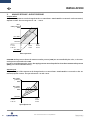
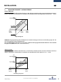
Setpoint span
The pressure span of the setpoint can be changed via the DaS-HD software. Switch Module 1 to "Rescale" in the "Pa-
rameter/Setpoint" section. The span is between +10 and +150 %.
CAUTION: Outlet pressures above the maximum outlet pressure (PMR) are not controlled by the valve, i.e. the max.
outlet pressure is limited to the PMR.
In order to avoid damaging the sensor, the supply pressure must always be less than the maximum inlet pressure
(MAP) (see Technical Characteristics).
3. ANALOG SETPOINT - OUTLET PRESSURE
Setpoint offset
The pressure setpoint zero can be changed via the DaS-HD software. Switch Module 1 to "Rescale" in the "Parameter/
Setpoint" section. The zero range is max. -50 ... +100 %.
Span adjustment
Offset adjustment
Max.
outlet pressure
PMR
SHUT-OFF
10 V
20 mA
20 mA
0
0
4
50 mV
0.1 mA
4.08 mA
Factory
setting: 0%
Max. outlet
pressure
PMR
SHUT-OFF
Max. outlet
pressure
PMR
Factory
setting: 100%
50% setting

INSTALLATION
GB
7
Visit our website at Emerson.com/AVENTICS
4. TECHNICAL CHARACTERISTICS
CONSTRUCTION INSTALLATION
Pilot operated valve
Body: Aluminium
Internal parts: Stainless steel, brass, aluminium and POM
Seals: Fluorelastomer (FPM)
Degree of protection: IP65
Assembly position: any; for optimum performance
vertically with solenoid at the top.
Air: free of condensatei
Connections: without hemp or Teon sealing tape
Electrical connection: Select a wire section that will
give a a voltage drop of less than 2 volts at 2A.
4.1 FLUID CHARACTERISTICS
FLUIDS : Air or neutral gas, free of condensate, lubricated or not
Class 5 to ISO 8573-1
PORTS : G1/4
MAX. INLET PRESSURE : 12 bar
PRESSURE RANGE : see Section 1.1
TEMPERATURE / FLUID : 0...50 °C
TEMPERATURE / AMBIENT : 0...50 °C
HYSTERESIS : <0,25% of span
LINEARITY : <0,25% of span
REPEATABILITY : <0,25% of span
4.2 SPECIFICATIONS
nominal
diameter
DN
stabilised
voltage *
max. power
(W)
max. current
(mA)
insulation
class
degree of
protection
flow
electrical connection
coeffi-
cient Kv
(Nm
3
/h)
at 6 bar
(l/min -
ANR)
6
24 V DC
+/-10%
5 240 F IP65 1,12 1200
8-pin M12 connector,
A coded
(not supplied)
* Max. ripple: 10 %
Setpoint input : 0 ... 10 V (100 kOhm input resistance)
0 ... 20 mA / 4 ... 20 mA (250 Ohm input resistance)
Feedback output : 0 ... 10 V (max. 10 mA), short-circuit protected
0 ... 20 mA / 4 ... 20 mA (max. 24 VDC)
Digital output : pnp; open collector; max. 200 mA/4.8W, short-circuit protected
HIGH (24 VDC) if feedback=setpoint
LOW (open) if feedback≠setpoint

INSTALLATION
GB
8
Visit our website at Emerson.com/AVENTICS
INSTALLATION AND OPERATING INSTRUCTIONS
1. Before putting into operation carefully check all electrical connections and the supply voltage (24 VDC ±10 %).
Overload can destroy the electronics. Recommended pre-fuse T2.0 A.
2. The electrical connection is made with a round connector M12x1. The connector must meet the requirements
of DIN 60079-15.
WARNING:
Do not disconnect the connector while under voltage!
When disconnected from power, use supplied protection cover to ensure IP protection.
3. Use shielded cables for the electrical connection of the valve. The shield, connector and control cabinet must
be EMC compliant. The valve body must be electrically connected to ground (PE, machine ground). Do not run
control cables parallel to high-voltage lines, servo-motor control cables etc.
4. Min. wire cross-section of supply voltage cable: 0.25 mm
2
.
For longer cabling distances use larger cross-section cables as required.
5. Make sure that the valve is under pressure when a setpoint signal is applied to the valve (applying a setpoint
signal with no pressure on the valve will cause it to overheat).
6. The valve is factory adjusted.
7. The product must be returned to the factory for repair.
WARNING NOTES
These products are intended for use in industrial compressed air systems only. Do not use these products where
pressures and temperatures can exceed those listed under SPECIFICATIONS. Please also see the corresponding prod-
uct specication sheets.
Before using these products with uids other than those specied, for non-industrial applications, life-support sys-
tems, or other applications not within published specications, consult ASCO Numatics.
Through misuse, age, or malfunction, components used in uid power systems can fail in various modes.
The system designer is warned to consider the failure modes of all component parts used in fluid power systems
and to provide adequate safeguards to prevent personal injury or damage to equipment in the event of such
failure.
System designers must provide a warning to end users in the operating manual if protection against a failure mode
cannot be adequately ensured.
System designers and end users are cautioned to review specic warnings found in instruction sheets packed and
shipped with these products.
5. ACCESSORIES
description
catalogue number
Supply cable 5 m; 8x0,50 mm
2
; straight connector
N43802302700000
Supply cable 10 m; 8x0,50 mm
2
; straight connector
N43802302800000
Supply cable 10 m; 8x0,50 mm
2
; right-angle connector
N43802302900000
Programming cable 2 m; M12 to RJ45 connector
N43802302600000


IM14277-DE/R02
Installationshandbuch
Digitaler Druckregler
Sentronic
HD
Baureihe 616
DE

DE
INSTALLATION
INHALT
1. Beschreibung ............................................................................................................................................ 13
1.1 Bestellangaben ................................................................................................................................ 13
1.2 Bedienelemente .............................................................................................................................. 14
1.3 Betriebszustände............................................................................................................................. 14
2. Elektrischer Anschluss ................................................................................................................................ 15
3. Analoger Sollwert - Ausgangsdruck ........................................................................................................... 16
4. Technische Daten ....................................................................................................................................... 17
4.1 Fluidtechnische Daten ..................................................................................................................... 17
4.2 Kennwerte ...................................................................................................................................... 17
5. Zubehör ..................................................................................................................................................... 18
6. Wartung und Pege ................................................................................................................................... 19
7. Abmessungen und Gewichte ...................................................................................................................... 19
ANMERKUNGEN
DIE IN DIESEM HANDBUCH ENTHALTENEN ANGABEN KÖNNEN OHNE VORHERIGE ANKÜNDIGUNG GEÄNDERT WERDEN.
ASCO NUMATICS übernimmt keinerlei Haftung für technische oder redaktionelle Fehler oder Ungenauigkeiten oder für versehentlich entstehende
Schäden oder Folgeschäden, die durch die Bereitstellung dieses Handbuchs oder aus der Anwendung desselben entstehen.
DAS VORLIEGENDE HANDBUCH ENTHÄLT URHEBERRECHTLICH GESCHÜTZTE ANGABEN. KEIN TEIL DIESES HANDBUCHS DARF OHNE VORHERIGE
SCHRIFTLICHE GENEHMIGUNG VON ASCO NUMATICS AUF IRGENDEINE ART UND WEISE VERVIELFÄLTIGT ODER ÜBERTRAGEN WERDEN.
COPYRIGHT © 2016 - ASCO NUMATICS - Alle Rechte vorbehalten.
Dieses Produkt enthält elektronische Bauteile, die gegenüber elektrostati-
schen Entladungen (ESD) empndlich sind. Berührungen der elektrischen
Bauteile durch Personen oder Gegenstände können zu einer elektrostati-
schen Entladung führen, die das Produkt beschädigt oder zerstört.
Um das Risiko einer elektrostatischen Entladung zu vermieden, sind die
Handhabungshinweise und Empfehlungen nach EN 100015-1 zu beachten.
Zum elektrischen Anschließen oder Trennen des Produkts ist die Versor-
gungsspannung abzuschalten.
ESD
A C H T U N G
VORSICHT BEI HANDHABUNG VON
ELEKTROSTATISCH GEFÄHRDETEN
BAUTEILEN (EGB)
Dieses Produkt entspricht der Richtlinie 2014/30/EU und deren Ergänzungen über die Elektromagnetische Verträglichkeit. Es ist
nach CE zugelassen. Eine Konformitätserklärung steht auf Anfrage zur Verfügung.
Geben Sie bitte für die entsprechenden Produkte die Artikelnummer und Seriennummer an.
Hiermit erklären wir, dass das in diesem Installationshandbuch beschriebene Gerät in der von uns gelieferten Ausführung zum Einbau oder Zu-
sammenbau mit anderen Maschinen bestimmt ist, und dass die Inbetriebnahme so lange untersagt ist, bis festgelegt wurde, dass die Maschine in
die das Gerät eingebaut werden soll, den Bestimmungen der Richtlinie 2006/42/EG entspricht.
Die Handhabung, Montage und Inbetriebnahme, sowie Einstell- und Justierarbeiten dürfen ausschließlich von autorisiertem Fachpersonal durch-
geführt werden.
ACHTUNG! Wenn die Programmierschnittstelle am Ventil benutzt wird, können gefährliche Betriebszustände auftreten, da das
Ventil möglicherweise nicht mehr auf den angelegten analogen Sollwert reagiert.
Bei Inbetriebnahme und vor Änderungen der Ventileinstellungen sind Vorkehrungen gegen unkontrollierte Bewegung von An-
lagenteilen zu treffen.
!
11
Visit our website at Emerson.com/AVENTICS

DE
12
Visit our website at Emerson.com/AVENTICS
INSTALLATION
1. BESCHREIBUNG
Sentronic
HD
mit integriertem digitalem Regelkreis verbindet neueste Pneumatik-Technologie mit intelligenter
Elektronik. Diese Baureihe ermöglicht die exakte Regelung von Druck, Durchuss, Kraft, Geschwindigkeit
und Weg oder Winkelpositionen.
Durch die Möglichkeit der kaskadierten Regelung können mit Hilfe der DaS-HD-Software (Data Acquisition
Software) auch komplexe Regelkreise realisiert werden. Die digitale Steuerung bietet viele Vorteile bei der
Installation und der Inbetriebnahme sowie erweiterte Möglichkeiten, das Sentronic
HD
-Ventil an die verschie-
densten Anwendungen anzupassen.
• Digitale Drucksteuerung im geschlossenen Regelkreis: Ein interner Drucksensor misst den Eingangs-/Aus-
gangsdruck. Der Ausgangsdruck wird in Echtzeit eingeregelt.
• Regelparameter können mit der zusätzlichen DaS-HD-Software geändert werden: Diese Flexibilität ermöglicht
es, das Ventil an die verschiedensten Anwendungen anzupassen und die Ansprechzeit, das Überschwingen
und die Präzision des Ventils zu optimieren.
• Nach der Bestimmung der optimalen Parameter können diese zum persönlichen Gebrauch in einer Projekt-
Datei gespeichert werden, die auch für eine zukünftige Serien-Produktion an unsere Abteilung Product
Support eingesandt werden kann.
1.1 BESTELLANGABEN
Sentronic
HD
- Digitales elektronisches Druckregelventil
15-STELLIGER BESTELLSCHLÜSSEL
G 616 A C S I O I XXX PP
Gewindeanschluss Druckbereich
G = ISO 228 03 = 0...3 bar
06 = 0...6 bar
Produktbaureihe
10 = 0...10 bar
V1 = -1 ... (+3 bar)
616
Revisionsbuchstabe Optionen
A = Erstfreigabe A00 = Standard
Größe Eingang 2 / Display mit Tasten
4 = G1/4 + Druckhaltende Version 0 = Standard NC + Display
5 = G1/4 + Entlüftende Version 2 = Analoger Eingang 2 + Display
4 = Digitaler Eingang 2 + Display
Sollwert
6 = Frequenzeingang + Display *
0 = 0 - 10 V
1 = 0 - 20 mA
2 = 4 - 20 mA
3 = PWM - Frequenz *
Istwert Ausgang 2
0 = 0 - 10 V 0 = NC
1 = 0 - 20 mA 1 = Digitaler Ausgang
2 = 4 - 20 mA 2 = Analoger Ausgang 2
* Wenn Sollwert PWM-Frequenz gewählt wurde, ist
bei Eingang 2 Frequenzeingang nicht verfügbar

DE
13
Visit our website at Emerson.com/AVENTICS
INSTALLATION
1.2 BEDIENELEMENTE
1.3 BETRIEBSZUSTÄNDE
Shutoff:
Wird der Sollwert kleiner 0,5 %, so werden die Pilotventile stromlos geschaltet und das Ventil entlüftet voll-
ständig.
Übertemperatur:
Erreicht die interne Regelelektronik eine Temperatur größer 100 °C, so wird AUTOSAFE eingeschaltet.
Autosafe:
Überschreitet der Magnetstrom für länger als 20 Sekunden einen vorbestimmten, von der Mechanik abhän-
gigen Wert, so wird der Ausgangsstrom auf 70% reduziert, um eine Überhitzung des Ventils zu vermeiden.
1 Elektrische Versorgung,
M12-Leitungsstecker, 8 pol.
2 LC-Display
3 Bedienfeld
4 Programmierschnittstelle
(Ethernet TCP/IP)
5 Eingangsdruck
6 Druckausgang
7 Entlüftung
8 Erdung M4 Gewinde
1
2
7
6
3
5
8
4

DE
14
Visit our website at Emerson.com/AVENTICS
INSTALLATION
STECKERBELEGUNG / KABELBELEGUNG
M12-Leitungsstecker
8-polig, A-kodiert
Pin Beschreibung
8-adriges Kabel
(5 m, 10 m)
1 Digitaler Eingang weiß
2 +24 VDC-Spannungsversorgung braun
3 Sollwert-Masse SOLL- grün
4 Sollwert SOLL+ (PWM) gelb
5
Analoger Eingang 2 / Digitaler Eingang 2 / Frequenzeingang
grau
6 Analoger Ausgang rosa
7 Masse 24VDC blau
8 Digitaler Ausgang / Analoger Ausgang 2 rot
Gehäuse EMV-Abschirmung Schirm
Ansicht Ventil
2. ELEKTRISCHER ANSCHLUSS
Programmierschnittstelle Ethernet TCP/IP
M12-Leitungsstecker,
4-polig, D-kodiert
Ansicht Leitungsstecker
(das Gerät ist mit einer
Leitungsdose versehen)
❉) Es wird empfohlen, ein geschirmtes Kabel zu verwenden.
1. Das Ventil darf nur mit einer Versorgungsspannung von 24VDC ±10% und einer maximalen Welligkeit von 10%
betrieben werden. (Eine Einspeisung über Diodenbrücke ist nicht gestattet). Überspannungen und Welligkeiten
außerhalb dieser Toleranzen können zu einer Beschädigung der Elektronik führen.
2. Der maximale Strom des Druckschalters beträgt 200 mA/4,8W (PNP-Ausgang). Der Ausgang ist gegen Kurzschluss
und Überlast geschützt.
3. Bei Anschluss eines Relais (induktive Last) an den Druckschalterausgang ist eine Freilaufdiode oder ein Varistor zu
verwenden.
4. Zum Schutz gegen elektromagnetische Störungen ist ein abgeschirmtes Kabel zu verwenden.
5. Das Ventilgehäuse ist mit Hilfe der Erdungsklemme (ØM4) zu erden.

DE
15
Visit our website at Emerson.com/AVENTICS
INSTALLATION
Sollwert-Spanne
Die Druck-Spanne des Sollwerts kann über die DaS-HD-Software verändert werden. Hierzu im Abschnitt "Parameter/
Sollwert" das Modul 1 auf "Reskalieren" umschalten. Der Einstellbereich für die Spanne ist +10 ... +150 %.
WARNUNG: Ausgangsdrücke größer als PMR (Pressure Maximum Range) werden vom Ventil nicht geregelt, d.h. der
max. Ausgangsdruck wird auf PMR begrenzt.
Um eine Beschädigung des Sensors zu vermeiden, sollte der Versorgungsdruck immer kleiner als der maximale
Eingangsdruck (MAP) sein (siehe "Technische Daten").
3. ANALOGER SOLLWERT - AUSGANGSDRUCK
Sollwert-Nullpunkt
Der Druck-Nullpunkt des Sollwerts kann über die DaS-HD-Software verändert werden. Hierzu im Abschnitt "Parameter/
Sollwert" das Modul 1 auf "Reskalieren" umschalten. Der Einstellbereich für den Nullpunkt ist maximal -50 ... +100 %.
Einstellung der Spanne
Nullpunktabgleich
Max.
Ausgangsdruck
PMR
ABSCHALTUNG
10 V
20 mA
20 mA
0
0
4
5 V
10 mA
12 mA
50 mV
0.1 mA
4.08 mA
+50% PMR
-50% PMR
10 V
20 mA
20 mA
0
0
4
50 mV
0.1 mA
4.08 mA
Werkseitige
Einstellung: 0%
Max.
Ausgangsdruck
PMR
ABSCHALTUNG
Max.
Ausgangsdruck
PMR
Werkseitige
Einstellung: 100%
Einstellung: 50%

DE
16
Visit our website at Emerson.com/AVENTICS
INSTALLATION
4. TECHNISCHE DATEN
KONSTRUKTIONSMERKMALE EINBAU
Pilot gesteuertes Ventil
Gehäuse: Aluminium
Innenteile: Edelstahl, Messing, Aluminium und POM
Dichtungen: Fluorelastomer FPM
Schutzart: IP65
Einbaulage: beliebig, vorzugsweise vertikal mit Ma-
gnet nach oben
Luft: kondensatfrei
Anschlüsse: Ohne Hanf oder Teon-Band
Elektrischer Anschluss: Drahtquerschnitt so wählen,
dass bei 2A ein Spannungsabfall von weniger als 2
Volt auftritt.
4.1 FLUIDTECHNISCHE DATEN
MEDIUM : Luft oder neutrales Gas, kondensatfrei, geölt oder ungeölt
Klasse 5 nach ISO 8573-1
ANSCHLÜSSE : G1/4
MAX. EINGANGSDRUCK : 12 bar
DRUCKBEREICH : siehe Abschnitt 1.1
TEMPERATUR / MEDIUM : 0...50 °C
TEMPERATUR / UMGEBUNG : 0...50 °C
HYSTERESE : <0,25 % vom Endwert
LINEARITÄT : <0,25 % vom Endwert
REPRODUZIERBARKEIT : <0,25 % vom Endwert
Sollwerteingang : 0 ... 10 Volt (Eingangswiderstand 100 kOhm)
0 ... 20 mA / 4 ... 20 mA (Eingangswiderstand 250 Ohm)
Istwertausgang : 0 ... 10 Volt (max. 10 mA), kurzschlussfest
0 ... 20 mA / 4 ... 20 mA (max. 24 VDC)
Digitaler Ausgang : pnp; open collector; max. 200 mA/4,8W, kurzschlussfest
HIGH (24 VDC) für Ist=Soll
LOW (open) für Ist
≠Soll
4.2 KENNWERTE
Nennweite
DN
Spannung *
Leistungs-
aufnahme
max.
(W)
Strom-
aufnahme
max.
(mA)
Isolations-
klasse
Schutzart
Durchfluss
Elektrischer Anschluss
K
V
-Wert
(Nm
3
/h)
bei 6 bar
(Nl/min)
6
24 V DC
+/-10%
5 240 F IP65 1,12 1200
8-polige Leitungsdose M12,
A-codiert
(separat zu bestellen)
* Restwelligkeit: 10 %

DE
17
Visit our website at Emerson.com/AVENTICS
INSTALLATION
5. ZUBEHÖR
Bezeichnung
Artikel-Nr.
Spannungsversorgungskabel 5 m; 8x0,50 mm
2
; gerade Leitungsdose
N43802302700000
Spannungsversorgungskabel 10 m; 8x0,50 mm
2
; gerade Leitungsdose
N43802302800000
Spannungsversorgungskabel 10 m; 8x0,50 mm
2
; Winkel-Leitungsdose
N43802302900000
Programmierkabel 2 m; M12 auf RJ45-Stecker
N43802302600000
MONTAGE- UND BEDIENUNGSHINWEISE
1. Vor der Inbetriebnahme sorgfältige Kontrolle der elektr. Anschlüsse und der Versorgungsspannung (24
VDC ±10%). Überspannung kann die Elektronik zerstören.
Empfohlene Vorsicherung T 2.0 A
2. Der elektrische Anschluss erfolgt über einen Rundstecker M12x1. Der verwendete Stecker muss die Anforde-
rungen nach DIN 60079-15 erfüllen.
Sicherheitshinweis:
Der Stecker darf nicht unter Spannung gezogen werden!
Bei gezogenem Stecker ist zur Aufrechterhaltung des IP-Schutzgrades die mitgelieferte Schutzkappe aufzu-
stecken.
3. Für den elektr. Anschluss des Ventils sind abgeschirmte Kabel zu verwenden. Die Schirmanbindung, Stecker
und Schaltschrank sind EMV-gerecht zu erfolgen. Der Ventilkörper ist elektr. auf Masse (PE, Maschinenmasse)
zu legen. Ansteuerleitungen nicht parallel zu Starkstromleitungen oder Ansteuerleitungen von Servomotoren
etc. verlegen.
4. Der Leitungsquerschnitt der Versorgungsspannung sollte min. 0,25 mm
2
betragen.
Bei langen Zuleitungen ggf. noch größeren Kabelquerschnitt wählen.
5. Sicherstellen, dass das Ventil mit Druck beaufschlagt ist, sobald ein Sollwertsignal dem Ventil vorgegeben
wird (Sollwertvorgabe, ohne dass das Ventil mit Druck beaufschlagt ist, führt zu einer unzulässig starken Er-
wärmung des Ventils).
6. Das Gerät ist werkseitig abgeglichen.
7. Das Gerät muss zur Reparatur ins Werk eingeschickt werden.
SICHERHEITSHINWEISE
Diese Produkte sind ausschließlich in industriellen Druckluftsystemen zu verwenden. Sie sind dort einzusetzen, wo
die unter "Spezikationen" aufgeführten Druck- und Temperaturwerte nicht überschritten werden. Berücksichtigen
Sie bitte die entsprechende Druckschriftenseite.
Vor dem Einsatz der Produkte mit Flüssigkeiten sowie bei nicht industriellen Anwendungen, in lebenserhaltenden-
oder anderen Systemen, die nicht in den veröffentlichten Anleitungsunterlagen enthalten sind, wenden Sie sich bitte
direkt an ASCO Numatics.
Durch Missbrauch, Verschleiß oder Störungen können in Hydrosystemen verwendete Komponenten auf verschie-
dene Arten versagen.
Systemauslegern wird dringend empfohlen, die Störungsarten aller in Hydrosystemen verwendeten Kompo-
nententeile zu berücksichtigen und ausreichende Sicherheitsvorkehrungen zu treffen, um Verletzungen von Per-
sonen sowie Beschädigungen der Geräte im Falle einer solchen Störung zu verhindern.
Systemausleger sind verpichtet, Sicherheitshinweise für den Endbenutzer im Betriebshandbuch zu vermerken,
wenn der Störungsschutz nicht ausreichend gewährleistet ist.
Systemauslegern und Endbenutzern wird dringend empfohlen, die den Produkten beiliegenden Sicherheitsvor-
schriften einzuhalten.

DE
18
Visit our website at Emerson.com/AVENTICS
INSTALLATION
6. WARTUNG UND PFLEGE
Keine besonderen Anforderungen.
7. ABMESSUNGEN (mm), GEWICHTE (kg)
Gewicht: 1,6 kg
M12-Anschluss-
stecker, 8-polig
M12-Anschlussbuchse,
4-polig; Ethernet
-
 1
1
-
 2
2
-
 3
3
-
 4
4
-
 5
5
-
 6
6
-
 7
7
-
 8
8
-
 9
9
-
 10
10
-
 11
11
-
 12
12
-
 13
13
-
 14
14
-
 15
15
-
 16
16
-
 17
17
-
 18
18


AVENTICS Series 616 Sentronic HD Installation guide
- Type
- Installation guide
Ask a question and I''ll find the answer in the document
Finding information in a document is now easier with AI
in other languages
Related papers
-
Asco Series 616 Digital Pressure Regulator Sentronic Owner's manual
-
AVENTICS Series 616 Sentronic HD Installation guide
-
-
-
-
-
-
-
-
Other documents
-
-
-
JVC RM-HP790DU User manual
-
-
-
-
-
-