
xx
MSO70000/C, DSA70000B/C,
DPO70000B/C, DPO7000,
MSO5000, and DPO5000
Series Oscilloscopes
Specifications and Performance Verification
ZZZ
Technical Reference
*P077006305*
077-0063-05


MSO70000/C, DSA70000B/C,
DPO70000B/C, DPO7000,
MSO5000, and DPO5000
Series Oscilloscopes
Specifications and Performance Verification
ZZZ
Technical Reference
xx
Revision A
This document applies to firmware version 5.2.0 and above.
Warning
The servicing instructions are for use by qualified personnel
only. To avoid personal injury, do not perform any servicing
unless you are qualified to do so. Refer to all safety summaries
prior to performing service.
www.tektronix.com
077-0063-05

Copyright © Tektronix. All rights reserved. Licensed software products are owned by Tektronix or its subsidiaries
or suppliers, and are protected by national copyright laws and international treaty provisions.
Tektronix products are covered by U.S. and foreign patents, issued and pending. Information in this publication
supersedes that in all previously published m aterial. Specifications and price change privileges reserved.
TEKTRONIX a nd TEK are registered trademarks of Tektronix, Inc.
Pinpoint, TekLink, and RT-Eye are registered trademarks of Tektronix, Inc.
Contacting Tektronix
Tektronix, Inc.
14150 SW Karl Braun Drive
P.O. Box 5 0 0
Beaverton, OR 97077
USA
For product information, sales, service, and technical support:
In North America, call 1-800-833-9200.
Worldwide, visit www.tektronix.com to find contacts in your area.

Warranty
Tektronix warrants that this product will be free from defects in materials and workmanship for a period of one (1)
year from the date of shipment. If any such product proves defective during this warranty period, Tektronix, at its
option, either will repair the defective product without charge for parts and labor, or will provide a replacement
in exchange for the defective product. Parts, modules and replacement products used by Tektronix for warranty
work may be n
ew or reconditioned to like new performance. All replaced parts, modules and products become
the property of Tektronix.
In order to o
btain service under this warranty, Customer must notify Tektronix of the defect before the expiration of
the warranty period and make suitable arrangements for the performance of service. Customer shall be responsible
for packaging and shipping the defective product to the service center designated by Tektronix, with shipping
charges prepaid. Tektronix shall pay for the return of the product to Customer if the shipment is to a location within
the country in which the Tektronix service center is located. Customer shall be responsible for paying all shipping
charges, duties, taxes, and any other charges for products returned to any other locations.
This warranty shall not apply to any defect, failure or damage caused by improper use or improper or inadequate
maintenance and care. Tektronix shall not be obligated to furnish service under this warranty a) to repair damage
result
ing from attempts by personnel other than Tektronix representatives to install, repair or service the product;
b) to repair damage resulting from improper use or connection to incompatible equipment; c) to repair any damage
or malfunction caused by the use of non-Tektronix supplies; or d) to service a product that has been modified or
integrated with other products when the effect of such modification or integration increases the time or difficulty
of servicing the product.
THIS WARRANTY IS GIVEN BY TEKTRONIX WITH RESPECT TO THE PRODUCT IN LIEU OF ANY
OTHER WARRANTIES, EXPRESS OR IMPLIED. TEKTRONIX AND ITS VENDORS DISCLAIM ANY
IMPLIED WARRANTIES OF MERCHANTABILITY OR FITNESS FOR A PARTICULAR PURPOSE.
TEK
TRONIX’ RESPONSIBILITY TO REPAIR OR REPLACE DEFECTIVE PRODUCTS IS THE SOLE
AND EXCLUSIVE REMEDY PROVIDED TO TH E CUSTOMER FOR BREACH OF THIS WARRANTY.
TEKTRONIX AND ITS VENDORS WILL NOT BE LIABLE FOR ANY INDIRECT, SPECIAL, INCIDENTAL,
OR CONSEQUENTIAL DAMAGES IRRESPECTIVE OF WHETHER TEKTRONIX OR THE VENDOR HAS
ADVANCE NOTICE OF THE POSSIBILITY OF SUCH DAMAGES.
[W2 – 15AUG04]


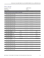
Table of Contents
General Safety Summary ......................................................................................... vi
Specifications (MSO70000/C Series, DSA/DPO70000B/C Series, and
DPO7000 Series)
Specifications (MSO70000/C Series, DSA/DPO70000B/C Series, and DPO7000 Series) .............. 1-1
Specifications (MSO/DPO5000 Series)
Specifications (MSO/DPO5000 Series)........................................................................ 2-1
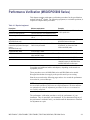
Performance Verification (MSO70000/C Series, DSA/DPO70000B/C
Series, and DPO7000 Series)
Performance Verification (MSO70000/C Series, DSA/DPO70000B/C Series, and DPO7000 Series) . 3-1
Conventions .................................................................................................. 3-2
Brief Procedures ( MSO70000/C Series, DSA/DPO70000B/C Series, and DPO7000 Series) .......... . 3-4
Self Tests...................................................................................................... 3-4
Functional Tests.............................................................................................. 3-5
Verify All Analog Input Channels .................................................................... 3-6
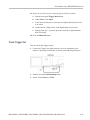
Verify the Time Base ................................................................................... 3-9
Verify the A (Main) and B (Delayed) Trigger Systems........................................... 3-12
Verify the File System................................................................................ 3-13
Verify the Digital Channels (MSO70000 Series Only) ........................................... 3-15
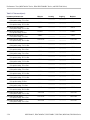
Perfor
mance Tests (MSO70000/C Series, DSA/DPO70000B/C Series, and DPO7000 Series) ....... 3-18
Prerequisites................................................................................................ 3-18
Equipment Required....................................................................................... 3-19
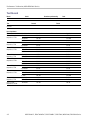
Test Record ................................................................................................. 3-22
Signal Acquisition System Checks ..... .................................................... ............. 3-42
Check DC Voltage Measurement Accuracy........................................................ 3-42
Check DC Gain Accuracy, ≥ 4 GHz models....................................................... 3-48
Check Offset Accuracy ≥ 4 GHz models........................................................... 3-56
Check Analog Bandwidth, < 3.5 GHz models..................................................... 3-60
Check Channel Bandwidth, ≥ 3.5 GHz models.................................................... 3-65
Check Input Resistance, ≥ 4 GHz models.......................................................... 3-71
Time Base System Checks................................................................................ 3-73
Check Timebase and Delay Time Accuracy and Reference...................................... 3-73
Check Delta Time Measurement Accuracy, < 4 GHz models.................................... 3-76
Check Delta Time Measurement Accuracy, ≥ 4 GHz models.................................... 3-80
MSO70000/C, DSA70000B/C, DPO7000B/C, DPO7000, MSO5000, DPO5000 Series i

Table of Contents
Trigger System
Checks.................................................................................... 3-85
Check Time Qualified Trigger Accuracy........................................................... 3-85
Check Sensitivity, Edge Trigger, DC Coupled..................................................... 3-89
Output Signal Checks ..................................................................................... 3-98
Check Aux Trigger Out .............................................................................. 3-98
Check Probe Compensation or Fast Edge Output ................................................ 3-100
Serial Trig
ger Checks (Optional on Some Models)................................................... 3-104
Check Serial Trigger Baud Rate Limits ........................................................... 3-104
Check Serial Trigger Clock Recovery Range..................................................... 3-110
Sine Wave Generator Leveling Procedure ............................................................. 3-114
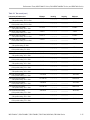
Performance Verification (MSO/DPO5000 Series)
Performance Verification (MSO/DPO5000 Series)........................................................... 4-1
Test Record ................................................................................................... 4-2
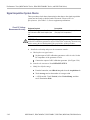
Performance Tests (MSO/DPO5000 Series)................................................................. 4-25
Prerequisites................................................................................................ 4-25
Self Test..................................................................................................... 4-26
Check
Input Impedance (Resistance).................................................................... 4-27
Check DC Balance......................................................................................... 4-28
Check DC Gain Accuracy ................................................................................ 4-30
Check Offset Accuracy.................................................................................... 4-33
Check Analog Bandwidth................................................................................. 4-35
Check Random Noise, Sample Acquisition Mode ........ .......... ................ ................ ... 4-38
Ch
eck Sample Rate and Delay Time Accuracy ........................................................ 4-40
Check Delta Time Measurement Accuracy ............................................................. 4-42
Check Digital Threshold Accuracy (MSO5000 only) ................................................. 4-44
Check Trigger Out ......................................................................................... 4-47
ii MSO70000/C, DSA70000B/C, DPO7000B/C, DPO7000, MSO5000, DPO5000 Series

List of Figures
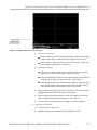
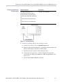
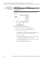
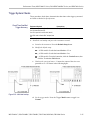
Figure 3-1: Toolbar and menu bar (< 4 GHz models shown)................................................ 3-3
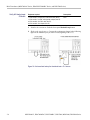
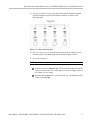
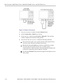
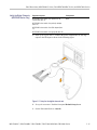
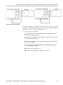
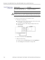
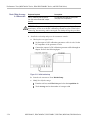
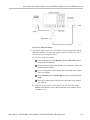
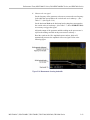
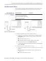
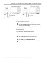
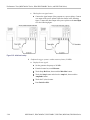
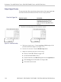
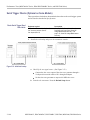
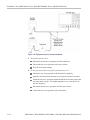
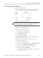
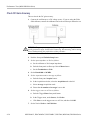
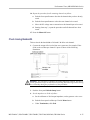
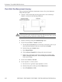
Figure 3-2: Universal test hookup for functional tests - Ch 1 shown....................................... 3-6
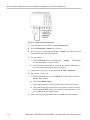
Figure 3-3: Channel button location............................................................................ 3-7
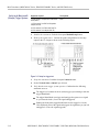
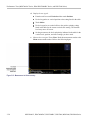
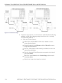
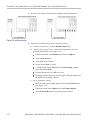
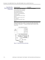
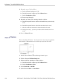
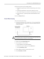
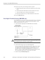
Figure 3-4: Setup for time base test .......................................................................... 3-10
Figure 3-5: Setup for trigger test.............................................................................. 3-12
Figure 3-6: Setup for the file system test .................................................................... 3-14
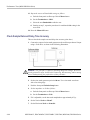
Figure 3-7: Setup for the digital channels test............................................................... 3-15
Figure 3-8: Initial test hookup ............... .............. .............. ..................................... 3-43
Figure 3-9: Measurement of DC accuracy at maximum offset and position........ .......... ........... 3-46
Figure 3-10: Measurement of DC gain accuracy ........................................................... 3-55
Figure 3-11: Initial test hookup ............ .............. .............. ................................ ....... 3-56
Figure 3-12: Measurement of offset accuracy............................................................... 3-58
Figure 3-13: Initial test hookup ................................ .......................... ..................... 3-61
Figure 3-14: Measurement of analog bandwidth ........................................................... 3-63
Figure 3-15: Initial test hookup ................................ .......................... ..................... 3-66
Figure 3-16: Measurement of analog bandwidth ........................................................... 3-69
Figure 3-17: Initial test hookup ................................ .......................... ..................... 3-71
Figure 3-18: Initial test hookup ................................ .......................... ..................... 3-73
Figure 3-19: Initial test hookup ................................ .......................... ..................... 3-74
Figure 3-20: Final test hookup................................................................................ 3-75
Figure 3-21: Delta time accuracy test hookup............................................................... 3-76
Figure 3-22: Delta time accuracy test hookup............................................................... 3-80
Figure 3-23: Initial test hookup ................................ .......................... ..................... 3-85
Figure 3-24: Measurement of time accuracy for pulse and glitch triggering ....................... ..... 3-86
Figure 3-25: Initial test hookup ................................ .......................... ..................... 3-90
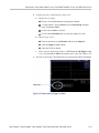
Figure 3-26: Measurement of trigger sensitivity - 50 MHz results shown .. .................. ........... 3-92
Figure 3-27: Initial test hookup ................................ .......................... ..................... 3-98
Figure 3-28: Measurement of trigger out limits............................................................. 3-99
Figure 3-29: Initial test hookup ........................ ...................... ...................... .......... 3-100
Figure 3-30: Measurement of probe compensator frequency............................................. 3-101
Figure 3-31: Subsequent test hookup ....................................................................... 3-102
Figure 3-32: Measurement of probe compensator amplitude......................... .......... .......... 3-102
Figure 3-33: Initial test hookup ........................ ...................... ...................... .......... 3-104
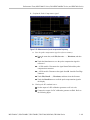
Figure 3-34: Isolated 0 triggering............................................................................ 3-107
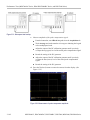
Figure 3-35: Isolated 1 triggering............................................................................ 3-109
Figure 3-36: Initial test hookup .................... .................. ........................................ 3-110
Figure 3-37: Clock recovery ................................................................................. 3-113
Figure 3-38: Sine wave generator leveling equipment setup ............................................. 3-114
Figure 3-39: Equipment setup for maximum amplitude ...... ................................ ............ 3-116
MSO70000/C, DSA70000B/C, DPO7000B/C, DPO7000, MSO5000, DPO5000 Series iii

Table of Contents
List of Tables
Table 1-1: Channel input and vertic al specifications, all MSO70000/C, DSA/DPO70000B/C, and
DPO7000 Series models .................................................................................... 1-1
Table 1-2: Horizontal and acquisition system specifications, a ll MSO70000/C, DSA/DPO70000B/C, and
DPO7000 Series models .................................................................................. 1-34
Table 1-3: Trigger specifications, all MSO70000/C, DSA/DPO70000B/C, and DPO7000 Series
models....................................................................................................... 1-41
Table 1-4: Serial Trigger specifications, all MSO70000/C and DSA/DPO70000B/C Series models
(optional on DPO7000 models) .......................................................................... 1-48
Table 1-5: Digital acquisition specifications (MSO70000/C Series) ..................................... 1-51
Table 1-6: Input/output port specifications, all MSO70000/C, DSA/DPO70000B/C, and DPO7000 Series
models....................................................................................................... 1-52
Table 1-7: Data storage specifications, all MSO70000/C, DSA/DPO70000B/C, and DPO7000 Series
models....................................................................................................... 1-56
Table 1-8: Power source specification, all MSO70000/C, DSA/DPO70000B/C, and DPO7000 Series
models....................................................................................................... 1-56
Table 1 -9: Mechanical specifications, all MSO70000/C, DSA/DPO70000B/C, and DPO7000 Series
models....................................................................................................... 1-57
Table 1-10: Environmental specifications, all MSO70000/C, DSA/DPO70000B/C, and DPO7000 Series
models....................................................................................................... 1-58
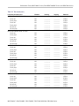
Table 2-1: Analog channel input and vertical specification.................................................. 2-1
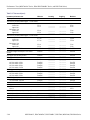
Table 2-2: Horizontal and acquisition system specifications ................................................ 2-9
Table 2-3: Trigger specifications.............................................................................. 2-11
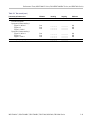
Table 2-4: Digital acquisition specifications, MSO5000 Series .......................................... 2-15
Table 2-5: P6616 Digital Probe specifications .............................................................. 2-
15
Table 2-6: Display specifications ............................................................................. 2-16
Table 2-7: Input/Output port specifications.................................................................. 2-16
Table 2-8: Data storage specifications........................................................................ 2-17
Table 2-9: Power source specifications ...................................................................... 2-17
Table 2-10: Environmental specifications ................................................................... 2-17
Table 2-11: Mechanical specifi cations ....................................................................... 2-18
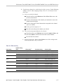
Table 3-1: Vertical settings ..................... ........................ .............. ........................ ... 3-8
Table 3-2: Test equipment ..................................................................................... 3-19
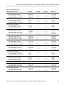
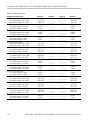
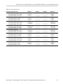
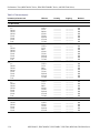
Table 3-3: Test record.......................................................................................... 3-23
Table 3-4: DC voltage measurement accuracy .............................................................. 3-44
Table 3-5: Gain accuracy ...................................................................................... 3-49
Table 3-6: Offset accuracy..................................................................................... 3-57
Table 3-7: Analog bandwidth, < 3.5 GHz models .......................................................... 3-62
Table 3-8: Channel bandwidth ≥4 GHz models............................................................. 3-67
Table 3-9: Channel bandwidth 3.5 GHz model ............................................................. 3-67
iv MSO70000/C, DSA70000B/C, DPO7000B/C, DPO7000, MSO5000, DPO5000 Series

Table of Contents
Table 3-10: Del
ta time measurement s ettings .................................... .............. ............. 3-78
Table 3-11: Delta time measurement settings ............................................................... 3-81
Table 3-12: Trigger settings for ≥ 4 GHz models........................................................... 3-95
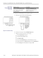
Table 3-13: Serial pattern data ............................................................................... 3-105
Table 3-14: Word recognizer data ........................................................................... 3-108
Table 3-15: Clock recovery input frequencies and baud rates............................................ 3-112
Table 4-1: R
equired equipment ................................................................................. 4-1
Table 4-2: Gain expected worksheet ......................................................................... 4-32
Table 4-3: Maximum bandwidth frequency worksheet .................................................... 4-37
MSO70000/C, DSA70000B/C, DPO7000B/C, DPO7000, MSO5000, DPO5000 Series v

General Safety Summary
General Safet
ySummary
Review the fo
llowing safety precautions to avoid injury and prevent damage to
this product or any products connected to it.
To avoid potential hazards, use this product only as specified.
Only qualified personnel should perform service procedures.
While using this product, you may need to access other parts of a larger system.
Read the safety sections of the other component manuals for warnings and
cautions related to operating the system.
To Avoid Fire or Person al
Injury
Use proper power cord. Use only the power cord specified for this product and
certified for the country of use.
Connect and disconnect properly. Do not connect or disconnect probes or test
leads while they are connected to a voltage source.
Ground the product. This product is grounded through the grounding conductor
of the power cord. To avoid electric shock, the grounding conductor m ust be
connected to earth ground. Before making connections to the input or output
terminals of the product, ensure that the product is properly grounded.
Observe all terminal ratings. To avoid fire or shock hazard, observe all ratings
and markings on the product. Consult the product manual for further ratings
information before making connections to the product.
The inputs are not rated for connection to mains or Category II, III, or IV circuits.
Connect the probe reference lead to eart
h ground only.
Power disconnect. The power cord disconnects the product from the power source.
Donotblockthepowercord;itmustremain accessible to the user at all times.
Do not operate without covers. Do not operate this product with covers or panels
removed.
Do not operate with suspected failures. If you suspect that there is damage to this
product, have it inspected by qualified service personnel.
Avoid exposed circuitry. Do not touch exposed connections and components when
power is present.
Do not operate in wet/damp conditions.
Do not operate in an explosive a tmosphere.
Keep product surfaces clean and dry.
Provide proper ventilation. Refer to the manual’s installation instructions for
details on installing the product so it has proper ventilation.
vi MSO70000/C, DSA70000B/C, DPO7000B/C, DPO7000, MSO5000, DPO5000 Series

General Safety Summary
TermsinThisManual
These terms may
appear in this manual:
WARNING. Warning statements identify conditions or practices that could result
in injury or loss of life.
CAUTION. Caution statements identify conditions or practices that could result in
damage to this product or other property.
Symbols and Terms on the
Product
These terms may appear on the product:
DANGER in
dicates an injury hazard immediately accessible as you read
the m arking.
WARN IN G
indicates an injury hazard not immediately accessible as you
read the marking.
CAUTIO
N indicates a hazard to property including the product.
The following symbol(s) may appear on the product:
MSO70000/C, DSA70000B/C, DPO7000B/C, DPO7000, MSO5000, DPO5000 Series vii

General Safety Summary
viii MSO70000/C, DSA70000B/C, DPO7000B/C, DPO7000, MSO5000, DPO5000 Series

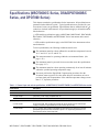
Specifications (MSO70000/C Series,
DSA/DPO70000B/C Series, and DPO7000
Series)


Specifications (MSO70000/C Series, DSA/DPO70000B/C
Series, and DPO7000 Series)
This chapter contains the specifications for the instrument. All specifications are
guaranteed unless labeled "typical." Typical specifications are provided for your
convenience but are not guaranteed. Specifications that are marked with the
symbol are checked in this manual. All specifications apply to all models unless
noted othe
rwise.
≥ 4 GHz models spec ifications apply to MSO70000, MSO70000C, DSA70000B,
DSA70000C
, DPO70000B, and DPO70000C Series instruments unless noted
otherwise.
< 4 GHz mod
els specifications apply to the DPO7000 Series instruments unless
noted otherwise.
To meet s
pecifications, the following conditions must be met:
The instrument must have been calibratedinanambienttemperaturebetween
18 °C an
d28°C(64°Fand82°F).
The instrument must be operating within the environmental limits. (See
page 1
-58.)
The i nstrument must be powered from a source that meets the specifications.
(See
page 2-17.)
The instrument must have been operating continuously for at least 20 minutes
wit
hin the specified operating temperature range.
You must perform the Signal Path Compensation procedure after the
20
-minute warm-up period. See the online help for instructions on how to
perform signal path compensation. If the ambient temperature changes more
than 5 °C, repeat the procedure.
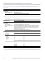
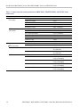
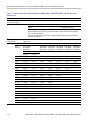
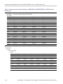
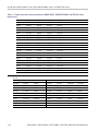
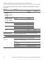
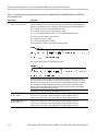
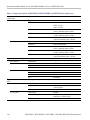
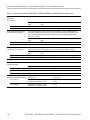
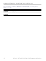
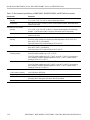
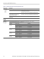
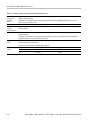
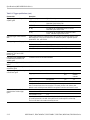
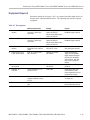
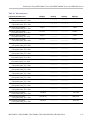
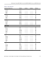
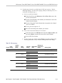
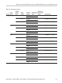
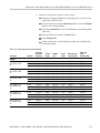
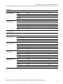
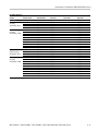
Table 1-1: Channel input and vertical specifications, all MSO70000/C, DSA/DPO70000B/C, and DPO7000 Series models
Characteristic Description
Number of channels
Four channels, all identical
Input connector
≥ 4 GHz models TekConnect. Power supply compatible with VPI.
< 4 GHz models BNC and VPI probe
Input coupling
≥ 4 GHz models DC 50 Ω and GND. GND coupling disconnects the input connector from all channel input
circuitry and connects a ground reference to the channel input circuitry.
< 4 GHz models DC, AC, or GND. G ND coupling approximates ground reference by measuring an unused
preamplifier input that has been connected to ground. The s ignal being measured is not
disconnected from the channel input load.
MSO70000/C, DSA70000B/C, DPO7000B/C, DPO7000, MSO5000, DPO5000 Series 1–1

Specifications (MSO70000/C Series, DSA/DPO70000B/C Series, and DPO7000 Series)
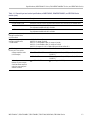
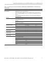
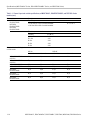
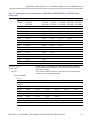
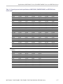
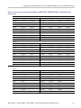
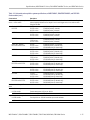
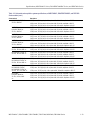
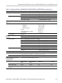
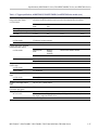
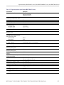
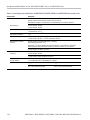
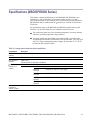
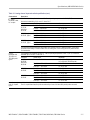
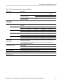
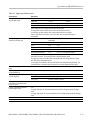
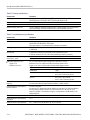
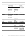
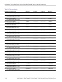
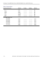
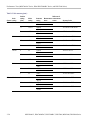
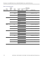
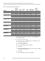
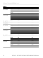
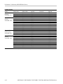
Table 1-1: Channel input and vertical s pecifications, all MSO70000/C, DSA/DPO70000B/C, and DPO7000 Series
models (cont.
)
Characteri
stic
Descriptio
n
Input resistance,
≥ 4 GHz models
100 mV FS to 995 mV FS: 50 Ω ±1.5% at 25 ºC (77 ºF)
50 Ω ± 2% over 10 to 45 ºC (50 to 113 ºF), type tested
1 V FS to 5 V FS: 50 Ω ±2.2 Ω over 10 to 45 ºC (50 to 113 ºF), type tested
Input impedance, DC coupled,
< 4 GHz models
1MΩ, DC coupled 1 MΩ ±1%inparallelwith13pF±2pF
50 Ω, DC coupled 50 Ω ±1%,typical
<1 V
RMS
for <1.0 V/Full Scale settings
Maximum input voltage,
≥ 4 GHz models
<5.0 V
RMS
for ≥ 1.0 V/Full Scale settings
Maximum input voltage,
< 4 GHz models
1MΩ – DC coupled,
1MΩ – AC coupled, or GND
coupled
150 V. Derate at 20 dB/decade to 9 V
RMS
above 200 kHz.
The maximum input voltage at the BNC, between center conductor and ground is 400 V peak.
The RMS voltage is limited to <150 V for arbitrary waveshapes including DC. The maximum
pulse width for impulses with peaks over 150 V i s 50 μs. Example: At 0 V to 400 V peak,
rectangular wave, the duty factor is 14%.
The m aximum transient withstand voltage is ± 800 V peak.
50Ω 5 V RMS, with peaks ≤ ±24V
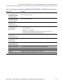
Input VSWR, typical
≥ 4 GHz models
Input Frequency
VSWR < 1 V/Full Scale VSWR ≥ 1V/FullScale
1.25
1.5
2.1
2.5
3.2
1.2
1.2
1.5
1.5
1.9
<2.5 GHz
<6 GHz
<14 GHz
<15 GHz
<20 GHz
Measured with a TekConnect SMA adapter and a network analyzer
< 4 GHz models f
in
<3.5 GHz
f
in
<2.5 GHz
f
in
<2 GHz
f
in
<1 GHz
3.0
2.0
1.5
1.2
Number of digitized bits
8bits
Digitizer nonlinearity, typical
< 1.0 DL (digitization level), differential; < 1 DL integral, independently based
1–2 MSO70000/C, DSA70000B/C, DPO7000B/C, DPO7000, MSO5000, DPO5000 Series

Specifications (MSO70000/C Series, DSA/DPO70000B/C Series, and DPO7000 Series)
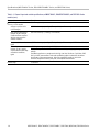
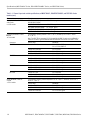
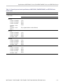
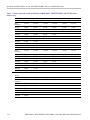
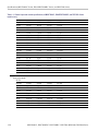
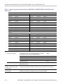
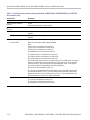
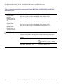
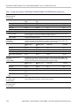
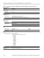
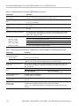
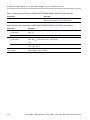
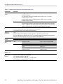
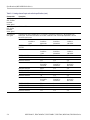
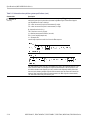
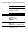
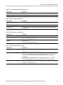
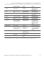
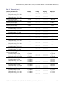
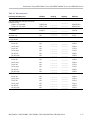
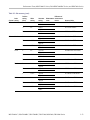
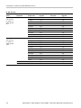
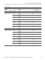
Table 1-1: Channel input and vertical specifications, all MSO70000/C, DSA/DPO70000B/C, and DPO7000 Series
models (cont.
)
Characteri
stic
Descriptio
n
Sensitivit
y range
≥ 4 GHz mode
ls, 50 Ω
100mV/Ful
lScaleto5V/FullScale. Below100mV/FullScale,Full Scale(FS)issoftwarezoom.
<4GHzmod
els, 50 Ω
1 mV/div t
o 1 V/division, in a 1-2-5 sequence
Fine adjustment available with ≥1% resolution
< 4 GHz models, 1 MΩ 1 mV/div to 10 V/division, in a 1-2-5 sequence
Fine adjustment available with ≥1% resolution
DC gain accuracy, sample or
average acquisition mode,
≥ 4 GHz models
±2%
DC gain accuracy, sample or
average acquisition mode,
< 4 GHz models
± 1.0% with 0 V net offset
Add 0.5% for ranges <2 mV/div
Add 1.5% x | net offset/Max offset | for ranges <5 mV/div
Add 0.5% x | net offset/Max offset | for ranges ≥ 5 mV/div
Add 0.5% for ranges ≥ 1V/divin1MΩ coupling and with net offset >10 V
DC vol
tage measurement
accuracy, ≥ 4 GHz models
Gain setting DC measurement accuracy
100 mV/FS to 995 mV/FS ±[2% | reading - net offset| + 0.35% | net offset | +1.5 mV
+ 0.014 FS]
Avera
ge acquisition mode
( ≥16 averages)
1 V/FS to 5 V/FS ±[2% | reading - net offset | + 0.35% | net offset | +7.5 mV
+0.0
14 FS]
Delta voltage measurement
bet
ween any two averages
of ≥16 waveforms acquired
under the same setup and
amb
ient conditions
100
mV/FS to 5 V/FS
±[2
% | reading | + 0.008 FS]
MSO70000/C, DSA70000B/C, DPO7000B/C, DPO7000, MSO5000, DPO5000 Series 1–3

Specifications (MSO70000/C Series, DSA/DPO70000B/C Series, and DPO7000 Series)
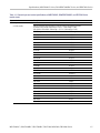
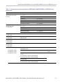
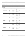
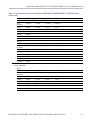
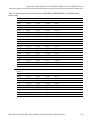
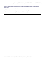
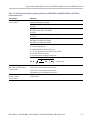
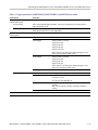
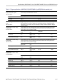
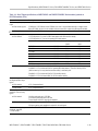
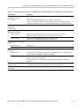
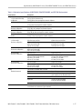
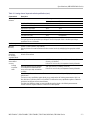
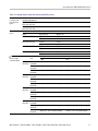
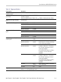
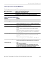
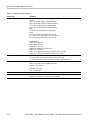
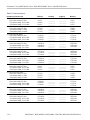
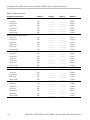
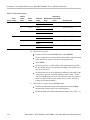
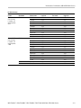
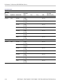
Table 1-1: Channel input and vertical s pecifications, all MSO70000/C, DSA/DPO70000B/C, and DPO7000 Series
models (cont.
)
Characteri
stic
Descriptio
n
DC voltage measurement
accuracy, < 4 GHz models
DC accuracy
(in volts)
Average acquisition mode
( ≥16 averages)
±(DC Gain Accuracy × | reading -(offset - position) | + offset accuracy + 0.1 division)
Delta voltage measurement
between any two averages
of ≥16 waveforms acquired
with the same setup and
ambient conditions
±(DC Gain Accuracy × | reading | + 0.05 division)
Sample acquisition mode,
typical
±(DC GainAccuracy × |reading-(offset -position) | + offsetaccuracy+ 0.15 division + 0.6 mV)
±(DC Gain Accuracy × | reading | + 0.15 division + 1.2 mV)
Delta voltage measurement
between any two samples
acquiredw ith thesamesetup
and ambient conditions,
typical
Convert offset, position and the constant offset term to volts by multiplying by the appropriate
volts/div.
Specification applies to any sample and to the High, Low, Max, Min, Mean, Cycle Mean, RMS,
and Cycle RMS measurements. Delta volts speci fi cation applies to subtractive calculations
involving two of these measurements. Delta volts specification applies to the Positive
Overshoot, Negative Overshoot, peak-peak, and amplitude measurements.
Position range ± 5 divisions
1–4 MSO70000/C, DSA70000B/C, DPO7000B/C, DPO7000, MSO5000, DPO5000 Series
Page is loading ...
Page is loading ...
Page is loading ...
Page is loading ...
Page is loading ...
Page is loading ...
Page is loading ...
Page is loading ...
Page is loading ...
Page is loading ...
Page is loading ...
Page is loading ...
Page is loading ...
Page is loading ...
Page is loading ...
Page is loading ...
Page is loading ...
Page is loading ...
Page is loading ...
Page is loading ...
Page is loading ...
Page is loading ...
Page is loading ...
Page is loading ...
Page is loading ...
Page is loading ...
Page is loading ...
Page is loading ...
Page is loading ...
Page is loading ...
Page is loading ...
Page is loading ...
Page is loading ...
Page is loading ...
Page is loading ...
Page is loading ...
Page is loading ...
Page is loading ...
Page is loading ...
Page is loading ...
Page is loading ...
Page is loading ...
Page is loading ...
Page is loading ...
Page is loading ...
Page is loading ...
Page is loading ...
Page is loading ...
Page is loading ...
Page is loading ...
Page is loading ...
Page is loading ...
Page is loading ...
Page is loading ...
Page is loading ...
Page is loading ...
Page is loading ...
Page is loading ...
Page is loading ...
Page is loading ...
Page is loading ...
Page is loading ...
Page is loading ...
Page is loading ...
Page is loading ...
Page is loading ...
Page is loading ...
Page is loading ...
Page is loading ...
Page is loading ...
Page is loading ...
Page is loading ...
Page is loading ...
Page is loading ...
Page is loading ...
Page is loading ...
Page is loading ...
Page is loading ...
Page is loading ...
Page is loading ...
Page is loading ...
Page is loading ...
Page is loading ...
Page is loading ...
Page is loading ...
Page is loading ...
Page is loading ...
Page is loading ...
Page is loading ...
Page is loading ...
Page is loading ...
Page is loading ...
Page is loading ...
Page is loading ...
Page is loading ...
Page is loading ...
Page is loading ...
Page is loading ...
Page is loading ...
Page is loading ...
Page is loading ...
Page is loading ...
Page is loading ...
Page is loading ...
Page is loading ...
Page is loading ...
Page is loading ...
Page is loading ...
Page is loading ...
Page is loading ...
Page is loading ...
Page is loading ...
Page is loading ...
Page is loading ...
Page is loading ...
Page is loading ...
Page is loading ...
Page is loading ...
Page is loading ...
Page is loading ...
Page is loading ...
Page is loading ...
Page is loading ...
Page is loading ...
Page is loading ...
Page is loading ...
Page is loading ...
Page is loading ...
Page is loading ...
Page is loading ...
Page is loading ...
Page is loading ...
Page is loading ...
Page is loading ...
Page is loading ...
Page is loading ...
Page is loading ...
Page is loading ...
Page is loading ...
Page is loading ...
Page is loading ...
Page is loading ...
Page is loading ...
Page is loading ...
Page is loading ...
Page is loading ...
Page is loading ...
Page is loading ...
Page is loading ...
Page is loading ...
Page is loading ...
Page is loading ...
Page is loading ...
Page is loading ...
Page is loading ...
Page is loading ...
Page is loading ...
Page is loading ...
Page is loading ...
Page is loading ...
Page is loading ...
Page is loading ...
Page is loading ...
Page is loading ...
Page is loading ...
Page is loading ...
Page is loading ...
Page is loading ...
Page is loading ...
Page is loading ...
Page is loading ...
Page is loading ...
Page is loading ...
Page is loading ...
Page is loading ...
Page is loading ...
Page is loading ...
Page is loading ...
Page is loading ...
Page is loading ...
Page is loading ...
Page is loading ...
Page is loading ...
Page is loading ...
Page is loading ...
Page is loading ...
Page is loading ...
Page is loading ...
Page is loading ...
Page is loading ...
Page is loading ...
Page is loading ...
Page is loading ...
Page is loading ...
Page is loading ...
Page is loading ...
Page is loading ...
Page is loading ...
Page is loading ...
Page is loading ...
Page is loading ...
Page is loading ...
Page is loading ...
Page is loading ...
Page is loading ...
Page is loading ...
Page is loading ...
Page is loading ...
Page is loading ...
Page is loading ...
Page is loading ...
Page is loading ...
Page is loading ...
Page is loading ...
Page is loading ...
Page is loading ...
Page is loading ...
Page is loading ...
Page is loading ...
Page is loading ...
Page is loading ...
Page is loading ...
Page is loading ...
Page is loading ...
Page is loading ...
Page is loading ...
Page is loading ...
Page is loading ...
Page is loading ...
Page is loading ...
Page is loading ...
Page is loading ...
Page is loading ...
Page is loading ...
Page is loading ...
Page is loading ...
Page is loading ...
Page is loading ...
Page is loading ...
Page is loading ...
Page is loading ...
Page is loading ...
-
 1
1
-
 2
2
-
 3
3
-
 4
4
-
 5
5
-
 6
6
-
 7
7
-
 8
8
-
 9
9
-
 10
10
-
 11
11
-
 12
12
-
 13
13
-
 14
14
-
 15
15
-
 16
16
-
 17
17
-
 18
18
-
 19
19
-
 20
20
-
 21
21
-
 22
22
-
 23
23
-
 24
24
-
 25
25
-
 26
26
-
 27
27
-
 28
28
-
 29
29
-
 30
30
-
 31
31
-
 32
32
-
 33
33
-
 34
34
-
 35
35
-
 36
36
-
 37
37
-
 38
38
-
 39
39
-
 40
40
-
 41
41
-
 42
42
-
 43
43
-
 44
44
-
 45
45
-
 46
46
-
 47
47
-
 48
48
-
 49
49
-
 50
50
-
 51
51
-
 52
52
-
 53
53
-
 54
54
-
 55
55
-
 56
56
-
 57
57
-
 58
58
-
 59
59
-
 60
60
-
 61
61
-
 62
62
-
 63
63
-
 64
64
-
 65
65
-
 66
66
-
 67
67
-
 68
68
-
 69
69
-
 70
70
-
 71
71
-
 72
72
-
 73
73
-
 74
74
-
 75
75
-
 76
76
-
 77
77
-
 78
78
-
 79
79
-
 80
80
-
 81
81
-
 82
82
-
 83
83
-
 84
84
-
 85
85
-
 86
86
-
 87
87
-
 88
88
-
 89
89
-
 90
90
-
 91
91
-
 92
92
-
 93
93
-
 94
94
-
 95
95
-
 96
96
-
 97
97
-
 98
98
-
 99
99
-
 100
100
-
 101
101
-
 102
102
-
 103
103
-
 104
104
-
 105
105
-
 106
106
-
 107
107
-
 108
108
-
 109
109
-
 110
110
-
 111
111
-
 112
112
-
 113
113
-
 114
114
-
 115
115
-
 116
116
-
 117
117
-
 118
118
-
 119
119
-
 120
120
-
 121
121
-
 122
122
-
 123
123
-
 124
124
-
 125
125
-
 126
126
-
 127
127
-
 128
128
-
 129
129
-
 130
130
-
 131
131
-
 132
132
-
 133
133
-
 134
134
-
 135
135
-
 136
136
-
 137
137
-
 138
138
-
 139
139
-
 140
140
-
 141
141
-
 142
142
-
 143
143
-
 144
144
-
 145
145
-
 146
146
-
 147
147
-
 148
148
-
 149
149
-
 150
150
-
 151
151
-
 152
152
-
 153
153
-
 154
154
-
 155
155
-
 156
156
-
 157
157
-
 158
158
-
 159
159
-
 160
160
-
 161
161
-
 162
162
-
 163
163
-
 164
164
-
 165
165
-
 166
166
-
 167
167
-
 168
168
-
 169
169
-
 170
170
-
 171
171
-
 172
172
-
 173
173
-
 174
174
-
 175
175
-
 176
176
-
 177
177
-
 178
178
-
 179
179
-
 180
180
-
 181
181
-
 182
182
-
 183
183
-
 184
184
-
 185
185
-
 186
186
-
 187
187
-
 188
188
-
 189
189
-
 190
190
-
 191
191
-
 192
192
-
 193
193
-
 194
194
-
 195
195
-
 196
196
-
 197
197
-
 198
198
-
 199
199
-
 200
200
-
 201
201
-
 202
202
-
 203
203
-
 204
204
-
 205
205
-
 206
206
-
 207
207
-
 208
208
-
 209
209
-
 210
210
-
 211
211
-
 212
212
-
 213
213
-
 214
214
-
 215
215
-
 216
216
-
 217
217
-
 218
218
-
 219
219
-
 220
220
-
 221
221
-
 222
222
-
 223
223
-
 224
224
-
 225
225
-
 226
226
-
 227
227
-
 228
228
-
 229
229
-
 230
230
-
 231
231
-
 232
232
-
 233
233
-
 234
234
-
 235
235
-
 236
236
-
 237
237
-
 238
238
-
 239
239
-
 240
240
-
 241
241
-
 242
242
-
 243
243
-
 244
244
-
 245
245
-
 246
246
-
 247
247
-
 248
248
-
 249
249
-
 250
250
-
 251
251
-
 252
252
-
 253
253
-
 254
254
-
 255
255
-
 256
256
-
 257
257
-
 258
258
-
 259
259
-
 260
260
-
 261
261
-
 262
262


Ask a question and I''ll find the answer in the document
Finding information in a document is now easier with AI
Related papers
-
Tektronix TBS1000 Series User manual
-
Tektronix DPO5104 User manual
-
-
-
Tektronix MSO5204B Installation
-
-
-
-
-
Tektronix 6 series User manual
Other documents
-
Fluke PM 8914/001 CombiScope Serial Interface Cable User manual
-
Rigol MSO5000-E User manual
-
-
-
Focal Performance Expert DSA 500 RT User manual
-
-
Fluke Calibration 5522A User manual
-
 Solarton Metrology SI3300 User and Installation Manual
-
-
Agilent Technologies InfiniiVision 6000 Series User manual
