Page is loading ...

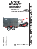
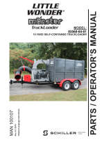
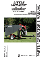
Park Ranger 2150
OperatOr's manual
LEAF SUCTION UNIT

2Operator’s Manual – Park Ranger 2150 Leaf Suction Unit
Introduction
Dear Customer,
Congratulations on your new Egholm product
The Park Ranger 2150 is a Danish-designed and manufactured product, which oers a very
exible way of maintaining outdoor areas.
Get the most out of your Park Ranger 2150 leaf suction unit
To ensure optimal performance from your Park Ranger 2150 leaf suction unit, please read this
manual carefully before using the machine. Failure to do so can result in personal injury and
damage to the machine.
Safety
The leaf suction unit is equipped with various devices to ensure optimal operational safety both
for the user and the surroundings. We ask you to pay particular attention to section 1.1 Safety.
The machine must only be serviced by professionals.
The leaf suction unit is designed for use by professionals only. On delivery, the user will receive
thorough training to become a competent operator. Do not lend the machine to anyone who has
not been thoroughly trained and who has not read this manual carefully.
The operator’s manual should be considered a permanent part of the machine and must remain
with it if the machine is sold.
Warnings
Some items in this operator’s manual are marked with this warning symbol.
The warning indicates areas where extra care must be taken to avoid personal
injury or damage to the machine and its accessories. The warning also shows
what you should pay special attention to.
Disclaimer
As it is the Egholm policy to make continuous improvements, we reserve the right to alter the
specications and equipment at any time without prior notice. Egholm accepts no liability for
errors or omissions in the operator's manual.
Contact Egholm
Should you have any questions regarding your Egholm product, do not hesitate to contact
Egholm.
Best regards,
Egholm A/S · Transportvej 27 · DK-7620 Lemvig
T. +45 97 81 12 05 · F. +45 97 81 12 10
Email: [email protected] · www.egholm.eu
!

3
Ideal for park areas, the leaf suction unit eciently cleans
up after defoliation and hedge trimming.
It has a working suction width of 1.05 metre, and with the
leaf collection hose it is able to reach even less accessible
areas like behind stonework and around hedges.
The leaf collection hose has a 4.2 metre reach and is
tted with a supporting arm to prevent it from damaging
hedges and ornamental plants while working. When not
in use, it is discreetly stored on top of the leaf suction unit,
occupying a minimum of space but always close at hand.
The leaf suction unit uses the hopper for grass collecting.
The hopper is an ecient two-in-one attachment, used
for both grass collecting when mowing and leaf collecting
in combination with the leaf suction unit.
Two sturdy turbines (one in the leaf suction unit and one in
the hopper) chop the leaves to bits and suck them up into
the hopper, ready for composting. When full, the hopper
is simply emptied by a hydraulic tip function directly onto
the compost heap, or – as enabled by a high tipping level
of up to 1.8 m – into a container. The leaf collection hose
does not have to be dismounted rst.
Operator’s Manual – Park Ranger 2150 Leaf Suction Unit
Contents
General information ..............................................................................4
1.1 Safety .....................................................................................4
1.2 EC Declaration of Conformity .................................................................6
1.3 Technical data .............................................................................7
Operator's manual ...............................................................................8
2.1 Unpacking the leaf suction unit ...............................................................8
2.2 Supplied components .......................................................................9
2.3 Assembly / Disassembly ....................................................................10
2.4 Checks before start-up .....................................................................14
2.5 Start-up ..................................................................................15
2.6 Adjustment ..............................................................................19
Service and maintenance ........................................................................20
3.1 Cleaning .................................................................................20
3.2 Maintenance .............................................................................21
3.3 Tips and Tricks ............................................................................22
3.4 Troubleshooting ..........................................................................23
3.5 Hydraulics diagram ........................................................................24
Conditions .....................................................................................25
4.1 Warranty .................................................................................25
4.2 Complaints ...............................................................................26
4.3 Disposal ..................................................................................26
Wearing parts ..................................................................................27
5.1 Wearing parts - Park Ranger 2150 Leaf suction unit .............................................27
Notes .........................................................................................29

4
3
1
2
3
4
1.1 Safety
Assembly
Always ensure that the engine cover lock on the bonnet is
closed and locked before tting the hopper.
(Picture 1)
Ensure that the hopper is correctly tted and that the
locking handle is locked in position during use. (Picture 2)
Ensure that the leaf suction unit is locked in place with the
attachment Lock during use. (Picture 3)
Avoid injury to ngers when attaching/detaching
Take care when attaching or detaching front or rear-
mounted attachments.
Avoid tipping accidents
Do not drive the machine in a place where it
can slide, tip or roll.
Do not drive on slopes with an incline of
more than 10 degrees. (Picture 4)
Be sure to park on a horizontal and even
surface when emptying.
Ensure the machine is not in an articulated
position when emptying.
Check and adjust the tyre pressure - min.
1.5 bar (22 psi) max. 2.5 bar (36 psi). Low
tyre pressure increases the risk of tipping.
General information
Do not drive on slopes with an incline of more than 10°
The engine cover lock must be engaged
Locked position
Attachment lock in locked position
Max. 10°
Operator’s Manual – Park Ranger 2150 Leaf Suction Unit
!
!
!
!

5
1
2
4
3
Avoid crushing hazard
Make sure no-one stands close to the
machine while in use
Make sure that no one is near the machine
while it is in use as there is a danger of
crushing.
NB!
As it is articulated, the rear end of the
machine swings out when turning. Make
sure that no-one stands near the machine
while it is in use. (Picture 1)
Avoid damage to your hearing
Always wear approved ear protectors
when using the machine. (Picture 2)
The leaf suction unit must not be started
if the leaf suction hose is not tted and
the selector switch is set to suction from
the leaf suction hose! (Picture 3)
Note that the turbine will continue
to rotate for 20-30 seconds after the
hydraulics have been disengaged.
The cab of the Park Ranger 2150 is approved as a roll-
over protection structure (ROPS). It is recommended
that this cab is tted for
operation in areas with a high risk of tipping.
Refer to the operator’s manual for the grass collector
(section 1.1 Safety) for safety precautions when using
the hopper for leaf collecting.
General information
Operator’s Manual – Park Ranger 2150 Leaf Suction Unit
!
!
!
!
!
Ensure that no-one stands in the working area
Use approved hearing protection
Suction using the leaf collection hose

6
1.2 EC Declaration of Conformity
Owner Egholm A/S
Address: Transportvej 27 · DK-7620 Lemvig
Tel.: +45 9781 1205
hereby declares that
The machine: Leaf Suction Unit
Type: LS100U
· has been manufactured in conformity with the provisions of the Machinery
Directive, Directive 2006/42/EC
· has been manufactured in conformity with the provisions of Machinery
Directive 2000/14/EU
Place: Lemvig, Denmark
Date:
Signature:
Knud Olsen, Senior Engineer
Operator’s Manual – Park Ranger 2150 Leaf Suction Unit
General information

7
1.3 Technical data
General information
Operator’s Manual – Park Ranger 2150 Leaf Suction Unit
Dimensions:
Length (L)
Width (W)
Height with cab and
hopper
Height, leaf suction unit
Attached:
3,100 mm
1,200 mm
1,950 mm
Storage dimensions:
800 mm
1,100 mm
900 mm
Technical data:
Type LS100U
Sound level, under Directive 2000/14/EU LwA: 108 dB(A)
Weight of leaf suction unit 90 kg
Vacuum width 1,050 mm
Ground clearance below vacuum nozzle, raised
180 mm
Range of leaf collection hose 4,200 mm
Volume of leaf collection hopper 470 litres
Tipping height 1,800 mm
Airow between the two turbines 2,250 m3/hour
Air speed between the two turbines 51 m/s
Air speed in the leaf collection hose 184 km/hour
Hydraulic oil type Texaco Rando HDZ46 or sim.
Operating speed 3-6 km/h
NB:
Specications may be changed without prior notice.

8
3
2
1
4
2.1 Unpacking the leaf suction unit
The leaf suction unit and leaf collection hose are delivered
on a pallet wrapped in plastic. (Picture 1)
The package contains:
1. The leaf suction unit and leaf collection hose
2. The suction hose connector for installation between the
leaf suction unit and hopper for grass collecting.
Remove the plastic packaging and lift the leaf suction unit
down from the pallet (use the lifting eye if necessary).
(Picture 2)
Place the leaf suction unit on the A-frame set-down feet.
During storage, the leaf suction unit must stand as shown
in picture 3, with the casters turned towards the vacuum
nozzle, and standing on the A-frame feet. (Picture 3)
If the leaf suction unit has to be transported later without
using a Park Ranger 2150, it should be securely mounted
on a pallet to avoid accidents. See picture 4.
Delivery
Operator's manual
Pallet mounting
Lifting eye
Casters Feet
Operator’s Manual – Park Ranger 2150 Leaf Suction Unit

1
2
3
45
9
Grass collection hose Leaf collection hose
Hose hanger Lock washer Threaded pin Rubber strap
Mount the hose hanger on the threaded pin to the right
behind the seat
Ax the suction hose using the rubber strap for
machines without cab
2.2 Supplied components
1. Suction hose
The hopper for grass collecting comes standard with a
suction hose for grass collection. The leaf collection hose
is mounted on the leaf suction unit when delivered.
Remove the grass collection hose.
Attaching the suction hose to machines without cab
Install the hose holder kit from the hopper on machines
without a cab. (Picture 2)
1. Install the threaded pin on the right side of the utility
machine chassis, behind the seat. (Picture 3)
2. Insert the hose hanger over the threaded pin. (Picture 3)
3. Ax the suction hose using the rubber strap. (Picture 4)
Attaching the suction hose to machines with cab
The hose holder is already attached to the cab.
Use the supplied rubber strap to ax the suction hose.
(Picture 5)
Operator's manual
Operator’s Manual – Park Ranger 2150 Leaf Suction Unit
Ax the suction hose using the rubber strap for
machines with cab
Hose holder kit for machines without cab

1
3
4
A B C
3
10
2
5
2.3 Assembly / Disassembly
Attaching the leaf suction unit:
1. Check that the leaf suction unit is standing on its set
down feet.
2. Spread the suction hose and hydraulic hoses out to the
sides so they cannot be driven over during attachment.
(Picture 1)
3. The locking handle on the A-frame of the machine must
be in the open position. (Picture 2)
4. Drive the machine right up to the leaf suction unit. Use
lever A to lower the A-frame until it is level with the leaf
suction unit (push the lever away from the seat). (Picture 3)
5. Drive forward until the A-frames overlap. (Picture 4)
6. Raise the A-frame by pulling lever A towards the seat
until the leaf suction unit is suspended free of the ground.
(Picture 3)
7. Stop the engine and lock the handbrake. Lock the
attachment in place with the locking handle on the
A-frame. (Picture 5)
See the operator’s manual for the grass collector for
instructions on installing this.
Spread the suction hose and hydraulic hoses
out to the sides before attaching
Interlink the A-frames from the attachment
and the machine
Lever A raises/lowers the A-frame
Operator's manual
Operator’s Manual – Park Ranger 2150 Leaf Suction Unit
Locking handle on the A-frame, open
Attachment locking handle in locked position

1
2
4
3
Operator's manual
C connector
Oil overow hose at connector D-3
Connector D-2
Hydraulically linking the leaf suction unit and hopper
Always check that all hydraulic hoses are
correctly attached. Incorrect connection
of hoses can result in a breakdown.
Connect the hydraulic hoses for the tip function with
hydraulic connector C on the machine. The hydraulic
hoses come out on the left side of the hopper. (Picture 1)
Connect the oil overow hose (1/4”) from the hopper
with hydraulic connector D-3 on the right-hand side of
the machine. (Picture 2)
Connect the return hose from the hopper with hydraulic
connector D2 (1/2” - female connector) on the right-
hand side of the machine.
(Picture 3)
Connect the oil overow hose (1/4”) from the leaf
suction unit above the oil overow hose from the hopper
on hydraulic connector D-3. (Picture 4)
Then connect the hydraulic hose (1/2”) from the leaf
suction unit with connector D-1 on the machine
(male connector from the leaf suction unit).
Operator’s Manual – Park Ranger 2150 Leaf Suction Unit
Oil overow hoses at connector D-3 Connector D-1
!

12
1
4
3
2
5
Feed the return hose from the leaf suction unit around the
machine to the left and attach it to the hopper (female
snap coupling on the leaf suction unit). (Picture 1)
Position the hydraulic hoses on the right side of the
machine as shown. Attach the rubber strap on the
hydraulic hose rmly to the bracket underneath the
chassis. (Picture 2)
Position the hydraulic hose on the left side of the machine
as shown. Attach the rubber strap on the hydraulic hose
rmly to the bracket underneath the chassis. (Picture 3)
The connections must match what is shown in pictures 4
and 5.
Removal:
Remove by following the above steps in reverse order.
Remember to put the protective caps back on the
hose connections after use.
Operator's manual
Operator’s Manual – Park Ranger 2150 Leaf Suction Unit
Return hose from the leaf suction unit
– with female connector
Secure hydraulic hoses - right side
Secure hydraulic hoses - left side
Hydraulic hoses attached – front

13
1
2
4
3
Operator's manual
Operator’s Manual – Park Ranger 2150 Leaf Suction Unit
Attaching the leaf collection hose:
1. Remove the grass collection hose. (Picture 1)
2. Attach the leaf collection hose instead. (Picture 1)
3. Connect the suction hose using the snap-lock hose clip.
(Picture 2)
4. Ax the suction hose using the rubber strap to the
hose holder on the cabin, if the machine has a cab.
(Picture 3)
5. Ax the suction hose using the rubber strap to the
hose holder on the front chassis, if the machine does not
have a cab. (Picture 4)
6. Always check that the suction hose is properly axed
before operating.
Removal:
Remove by following the above steps in reverse order.
Grass collection hose Leaf collection hose
Connect the suction hose using the hose clip
Machines with cab
Machines with no cab

1
3
3
6
4
2
5
14
2.4 Checks before start-up
Transportation
1. Lock the leaf suction unit in the horizontal position
using the locking pin during transportation. (Picture 1)
When using the leaf suction unit the locking pin must be in
the open, oating, position. The oating position ensures
that the leaf suction unit follows the terrain independently
of the Park Ranger 2150. (Picture 2)
2. Lock the A-frame on the Park Ranger 2150 using the
transport lock during transit to and from the work area.
(Picture 3)
Suction using the vacuum nozzle:
For suction using the vacuum nozzle, the selector switch
must be turned to the right, viewed from the front.
(Picture 4)
Suction using the leaf collection hose:
For suction using the leaf collection hose, the selector switch
must be turned to the left, viewed from the front. (Picture 5)
Warning!
Never start the leaf suction unit with the
leaf collection hose disconnected and the
selector switch set to suction using the
leaf collection hose.
Suction height adjustment
The suction height can be adjusted using the height
adjustment handle. This handle adjusts the wheel height
of both casters.
The closer the vacuum nozzle is to the ground, the more
powerful the suction will be. (Picture 6)
There is a height scale (1-7) on the side of the wheel spindle
Please also refer to section 2.4 of the operator’s manual
for the grass collector – Checks before start-up.
Locking pin locked - Transit Locking pin open - In use
Handle for adjusting the suction height
Transport lock – locked
Suction using the vacuum nozzle
Suction using the leaf collection hose
L
o
c
k
e
d
Operator's manual
Operator’s Manual – Park Ranger 2150 Leaf Suction Unit
!

2
4
11
3
1
2
A B C
15
2.5 Start-up
The leaf suction unit and hopper have been developed for
connection in series. This means both must be started at
the same time.
1. Start the Park Ranger 2150
(See the operator's manual for the basic machine, section 2.2)
2. Lower the leaf suction unit by pushing lever A away
from the seat. (Picture 1) Hold lever A out for approx.
2 seconds, as the leaf suction unit is then in a oating
position and will follow the contours of the terrain.
3. Turn the throttle until it is at least half open.
(Picture 2)
4. Start the leaf suction unit by pulling lever D on the right-
hand side of the machine in a slow movement. (Picture 3)
5. Stop the leaf suction unit by pushing lever D towards the
centre (neutral position) in a slow movement. (Picture 3)
Warning!
Make sure no one is standing close to the
machine while it is in use.
Warning!
As it is articulated, the rear end of the
machine swings out when turning.
Make sure that no-one stands near the
machine while it is in use.
NB!
It is recommended not to drive with a
higher engine speed than necessary,
to reduce the noise and the energy
consumption.
Warning!
The turbine will continue to rotate for
20-30 seconds after stopping.
The throttle must be at least half open
Start the leaf suction unit using lever D
Rais e an d lowe r th e lea f su c t io n un it u si ng le ver A
Operator's manual
Operator’s Manual – Park Ranger 2150 Leaf Suction Unit
!
!
!
!

5
3
2
4
1
16
Starting the leaf suction unit
1. Start “manual activation” of the leaf suction unit.
(Picture 1) (See the operator’s manual for the Park
Ranger
2150 basic machine, section 1.5 Operating levers and pedals).
2. Turn the throttle to fully open – run at full speed.
3. Turn the selector switch to suction using the leaf
collection hose. (Picture 2)
4. Open the leaf collection hose handle by pulling the
handle lock. (Picture 3)
5. Loosen the transport lock on the leaf collection hose.
(Picture 4)
6. The leaf collection hose is kept in place in the holder by
the vacuum of the turbines. Take the vacuum nozzle out of
the holder. The leaf collection hose will now come out and
is ready for use. (Picture 5)
Button to manually activate the leaf collection hose
Suction using the leaf collection hose
Pull out the lock and open the handle
Leaf collection hose transport lockTake the vacuum nozzle out of the holder
Operator's manual
Operator’s Manual – Park Ranger 2150 Leaf Suction Unit

3
1
2
17
Using the supporting arm for the leaf collection hose
Use the supporting arm when reaching the leaf collection
hose across hedges and ornamental plants.
1. Pull the supporting arm out of the lock. (Picture 1)
2.
Attach the leaf collection hose to the supporting arm
by clicking the snap hooks together – one on the leaf
collection hose and one on the supporting arm.
(Picture 2)
3. The leaf collection hose is now ready for use with the
supporting arm. (Picture 3)
Connect the snap hooks on the supporting arm
and leaf collection hose
Using the leaf collection hose
Pull the hose supporting arm out of the lock and
rotateout
Operator's manual
Operator’s Manual – Park Ranger 2150 Leaf Suction Unit

1
3
2
4
18
Place the vacuum nozzle in the holder
Help the leaf collection hose into position
Lock the handle around the leaf collection hose
Leaf collection hose transport lock
Storing the leaf collection hose
Place the vacuum nozzle in the holder and push the leaf
collection hose into place. The turbine vacuum will then
compact the leaf collection hose. (Picture 1+2)
Remove the supporting arm by unclicking the snap hooks.
Help the leaf collection hose properly into position.
(Picture 2)
Lock the handle around the leaf collection hose. (Picture 3)
Important!
When driving on public roads or over
long distances, the leaf collection hose
must be secured using the transport lock.
(Picture 4)
Operator's manual
Operator’s Manual – Park Ranger 2150 Leaf Suction Unit
!

1
2
19
2.6 Adjustment
Adjust the height of the leaf suction unit to achieve the
desired suction power and avoid stones etc. being drawn
into the hopper (stones can cause extensive wear).
Adjusting the leaf suction unit:
Set the leaf suction unit in the oating position by opening
the locking pin. (Picture 1)
Adjust the suction height using the height adjustment handle.
This handle adjusts the wheel height of both casters.
The closer the vacuum hose is to the ground, the more
powerful the suction will be. (Picture 2)
There is a height scale (1-7) on the side of the wheel spindle
Adjusting the suction height
Locking pin open – leaf suction unit in oating position
Operator's manual
Operator’s Manual – Park Ranger 2150 Leaf Suction Unit

1
20
3.1 Cleaning
To avoid turbine imbalances and vibration, the leaf suction
unit must be regularly cleaned and as required.
Clean using clean water and eventually a high-pressure
cleaner
Warning!
Stop the engine and completely detach
the leaf suction unit and hydraulic hoses
before cleaning. Wait until the turbine
has completely stopped rotating before
cleaning the vacuum nozzle.
After cleaning, it is important to set the leaf suction unit
selector switch to suction using the vacuum nozzle and
briey start the turbine to remove all water from the
turbine housing. (Picture 1)
Service and maintenance
Suction using the vacuum nozzle
Operator’s Manual – Park Ranger 2150 Leaf Suction Unit
!
/