Page is loading ...

1
1
RC-90 / RC-90B Single Stage Heat/Cool
Thermostat for Zone Control Systems
Installation Instructions
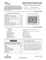
DESCRIPTION
The RC-90 is a precision digital thermostat designed for 24 VAC single stage heating and cooling systems. It
has the capability of being controlled both locally and by remote control. It offers programmability, stand-alone
operation, and robust, optically isolated communications with automation systems, utility control systems, and
personal computers. The RC-90B is equipped with a “cool blue” backlight display.
Electrical rating: 24 V; 3 A; 50/60 Hz
Maximum current: 2 A on any circuit, 3 A total
Thermostat operating current: less than 15 mA
The following requirements must be observed for installation in Europe: CE
1. This equipment must be installed in accordance with National wiring rules for the country in which it is
installed.
2. Fuses must be replaced only with IEC rated components.
3. All product labels, instructions and markings relating to safety must be translated to a language, which is
acceptable in the country in which this equipment is to be installed.
INSTALLATION
Before installing this thermostat:
1. Read all of the installation instructions carefully. Read the Owner's Manual carefully.
2. Ensure that this product is suitable for your application.
3. Ensure that wiring complies with all codes and ordinances.
4. Disconnect power to the control transformer to prevent electrical shock and damage to equipment.
5. Select an appropriate location to ensure an accurate temperature reading.
Location
When replacing an existing thermostat, install the RC-90 in the same location. If the existing location doesn't
meet the following criteria, choose a new location to mount the RC-90. When choosing a location for the
thermostat:
1. Ensure that the thermostat is mounted 5 feet above the floor and is at least 2 feet from an outdoor wall.
2. Ensure that the thermostat is located in an area where there is adequate air circulation.
3. Do not mount in the path of direct sunlight or of radiant heat generated by appliances.
4. Do not mount behind an outdoor wall, near a fireplace, or in the path of any air ducts.
Document Number 13I00-28 / Rev B / April, 2004
Copyright 1999-2004 Home Automation, Inc.
All Rights Reserved

2
2
Removing an existing thermostat
1. Disconnect the power to the control transformer.
2. Remove the cover to the existing thermostat.
3. Disconnect the wires going to each terminal on the thermostat. Label each wire with the letter or number
at the terminal.
4. Remove the existing plate or base from the wall.
MOUNTING
When mounting the RC-90, grasp the thermostat by the sides, avoiding the keys, and unsnap the base from the
face.
Holding the base to the wall so that the word "TOP" is upright and facing you:
1. Mark the two mounting holes on the wall using a pencil.
2. Drill a hole using a 3/16" bit at each mounting hole marking.
3. Install the two wall anchors supplied.
4. Slide the system wires through the opening in the base.
5. Mount the base to the wall using the two #6 x 1/2" self-tapping screws supplied - See Figure 1.
Figure 1

3
3
Connect each wire to the terminal strip on the thermostat base per the wiring diagram for your system
application - See Figures 4 - 7.
Form the thermostat wiring so that the cable lies flat between the terminal strip and the center of the base.
If a remote system is being used with the thermostat, connect the remote system wiring to the supplied cable
using the wire splices per the diagram for your remote system application - See Figures 9 - 10. Insert the cable
into the connector on the thermostat circuit board marked "COMM".
Upon completion of wiring the thermostat, push all excess wiring into the hole in the wall. Plug the hole with
the supplied insulating foam to ensure an accurate temperature reading by the thermostat.
Align the tabs of the thermostat face with the slots of the thermostat base. Gently push the thermostat face into
the thermostat base locking it into place - See Figure 2.
Figure 2 Figure 3
Note:
Be sure that the thermostat temperature sensor is standing up, and that it has not been damaged during
installation - See Figure 3.

4
4
TYPICAL WIRING DIAGRAMS
CAUTION:
Be sure to disconnect the power to the control transformer before removing or installing thermostat.
Do not short gas valve, fan, cool mode relay, heat mode relay, heat relay, or cool relay...even momentarily.
This will blow a non-replaceable fuse.
Do not attempt to hook up to live circuits. An accidental connection to a component on the thermostat circuit
board could cause damage to the thermostat.
Figure 4 - Thermostat power-up for test or demonstration purposes
Note: As a convenience to the installer, the compressor start up protection delay can be canceled. To cancel
the delay, press the Prog key 3 times, then press the Fan key 2 times.
POWER UP
1. Double check wiring, be sure that there are no stray wires or wire strands at the connections.
2. It is not necessary to connect the remote system (COMM) cable at this time.
3. Connect power to the control transformer and system. The display will show all segments for about 5
seconds.
4. Press the Fan key. The fan should come on. Press the Fan key again. The fan should go off.
5. Set the Mode to "HEAT". Use the up arrow key to raise the desired temperature setting above the current
temperature. Ensure that the heater unit comes on. Set the mode to "OFF". Ensure that the heat unit goes
off.
6. Set the Mode to "COOL". Use the down arrow key to lower the desired temperature setting below the
current temperature. Ensure that the cooling unit comes on. Set the mode to "OFF". Ensure that the
cooling unit goes off.
If the thermostat or system do not perform as stated above, recheck all wiring - See Troubleshooting Tips.

5
5
Figure 5 – Installation as a Master thermostat

6
6
Figure 6 – Installation as a Slave thermostat
Figure 7 - Installation as a Zone thermostat with separate
transformer - Required by some zone panels

7
7
NOTE ON ADDITIONAL OUTPUTS
The RC-90 has two additional outputs (B and O) for use with zoned heating and cooling systems. The B and O
terminals control the mode of operation (heating or cooling) of the zone control panel. The zone control panel
will recognize calls for heat (W) from the individual zones when the B terminal is energized, and calls for cool
(Y) when the O terminal is energized.
The RC-90 will energize (connect to R) the B terminal whenever the display shows "HEAT" or "HEAT AUTO"
mode, even if it is not calling for heat (W). Similarly, the RC-90 will energize the O terminal whenever the
display shows "COOL" or "COOL AUTO". Both B and O are Off when the display shows "OFF".
Therefore, the RC-90 can act as a Master to set the operating mode of the entire system (HEAT, COOL, or
OFF).
CONFIGURING THE BACKLIGHT ON THE RC-90B
The backlight on the RC-90B can be configured to one of three different modes: 1) on for 30 seconds when a
key is pressed, 2) always on, or 3) always off.
1) To configure the display backlight to turn on when a key is pressed, then back off 30 seconds later, set
the “JP2” (Select Backlight Mode) jumper to the “TIMED” position (between the top and middle pin on
the connector) - See Figure 8.
2) To configure the display backlight to always be on, set the “JP2” (Select Backlight Mode) jumper to the
“ON” position (between the middle and bottom pin on the connector) - See Figure 8.
3) To configure the display backlight to never come on (always off), remove the “JP2” (Select Backlight
Mode) jumper from the connector - See Figure 8.
DISABLE KEYS
The keys on the thermostat can be disabled to prevent anyone from controlling the thermostat locally. To
disable the keys, solder a wire jumper across “JP1” (two holes on the circuit board) - See Figure 8.

8
8
SOLDER WIRE JUMPER HERE SELECT BACKLIGHT
MODE (SET JUMPER)
TO DISABLE KEYS LOCALLY
Figure 8
INSTALLER SETUP
This section describes the items that the installer must setup as part of the thermostat installation. The Installer
Setup mode is used to configure the general operating parameters of the thermostat.
When in Installer Setup mode:
1. The small digits on the top of the display are the item number.
2. The large blinking digits in the center of the display are the value of the item number.
3. Press the Prog (>) key to advance to the next item.
4. Press the Hold (<) key to return to the previous item.
5. Use the arrow keys (∧−∨) to change the value of each item.
6. Do not set the values to anything other than the specified range for each item.
7. To exit Setup mode, press the Fan key.
The thermostat will automatically exit Setup mode after 20 seconds of no key activity.
To enter the Installer Setup mode, press the Prog key three times (day will flash), then press the Fan key.

9
9
The word "default" indicates the initial setting when the thermostat is delivered from the factory.
00 Address
If you are using Communications Mode 0 or 1, and you are installing more than one thermostat, each must be
set to a consecutive address, starting at 1. The default address setting is 1.
An address from 1- 127 may be selected.
01 Communications mode
The thermostat can communicate with remote systems in 4 different modes. These modes are:
0 300 baud, RS-232 mode (for use with personal computers)
1 100 baud, System mode (OmniLT, Omni, Omni II, OmniPro, and OmniPro II systems)
8 PESM mode, (use with Model 1503 automation systems)
24 Day/Night mode (for use with remote setback switch)
The default setting is 1.
02 System options
The thermostat can be configured with the following system options:
0 Auto changeover no fan with heat
1 Auto changeover fan on with heat
4 Manual changeover no fan with heat
5 Manual changeover fan on with heat
12 Heat only no fan with heat
13 Heat only fan on with heat
20 Cool only
The default setting is 0.

1
10
0
03 Display options
The thermostat can be configured to display the following attributes:
0 Celsius am/pm time format programmable
1 Fahrenheit am/pm time format programmable
2 Celsius 24-hour time format programmable
3 Fahrenheit 24-hour time format programmable
4 Celsius am/pm time format non-programmable
5 Fahrenheit am/pm time format non-programmable
6 Celsius 24-hour time format non-programmable
7 Fahrenheit 24-hour time format non-programmable
When connected to an HAI controller, the thermostat should be configured as "non-programmable". To disable
the clock and filter reminder displays, add “16” to each value.
The default setting is 1.
04 Calibration offset
This item is used to raise or lower the current temperature reading by 1 degree Fahrenheit or 1/2 degree Celsius.
If this item is set to 30, no change will be made. Each digit below 30 will lower to temperature, and each digit
above 30 will raise the temperature.
(1 = “- 29” to 59 = “+ 29” temperature units; 30 = No change)
The default setting is 30.
05 Cool setpoint limit
This item is used to limit the temperature setting in cool mode. The desired cool setting can never be set below
this setting.
The default setting is 51.
06 Heat setpoint limit
This item is used to limit the temperature setting in heat mode. The desired heat setting can never be set above
this setting.
The default setting is 91.
07 Not used
08 Not used

1
11
1
09 Cooling anticipator
This item adjusts the tendency of the thermostat to run the cooling system to refresh and dehumidify the air
before the temperature rises to the desired cool setting. A setting of 0 will disable this feature.
0 No anticipation
3-5 Normal anticipation
10 Maximum anticipation
The recommended setting for most forced air cooling systems is 4. A lower number will decrease the tendency
to run the cooling system below the cooling setting. A lower setting of 2 or 3 may be desired in dry climates.
The default setting is 4.
10 Heating anticipator
This item adjusts the tendency of the thermostat to turn the heating unit off before the desired heat setting is
reached. This is done to avoid overheating the air while the walls and furniture catch up. A setting of 0 will
disable this feature.
0 No anticipation
3-5 Normal anticipation
10 Maximum anticipation
The following settings are recommended:
Forced air systems: 4
Radiant systems: 6
A lower setting will decrease the tendency to turn off the heating system before the desired heat setting is
reached. If the heating system response time is slower, as are most radiant heating systems, a higher number
will help maintain an even space temperature.
The default setting is 4.
11 Cooling minimum on/off time (minutes)
This item is used to limit the on and off times of the cooling system. When the cooling system starts, it must
remain on for the minimum time set by this item. When the cooling system turns off, it must remain off for a
minimum time set by this item.

1
12
2
Setting Cycles per hour (maximum)
5 6
6 5
7 4
8 3.7
10 3
The recommended setting is 8 minutes. A higher setting may be appropriate for buildings with low heat
loss/gain. The default setting is 8.
12 Heating minimum on/off time (minutes)
This item is the same as the “Cooling minimum on/off time”, but for heating. The default setting is 8.
13 Not used
14 Clock adjust
If the clock on the thermostat is running faster or slower than the actual time, you can have the thermostat
automatically compensate up to 29 seconds per day. The thermostat will add or subtract the selected amount of
time daily.
(1 = “- 29” to 59 = “+ 29” seconds per day; 30 = No change)
The default setting is 30.
Note: If an HAI automation system is being used, the controller system time is sent to the thermostat every
minute. This adjustment will have no effect.
15 Filter reminder
The thermostat logs the amount of time the system fan has been running. When this setting reaches 0, the
thermostat will display a reminder to replace the filter. The setting is the amount of days (24 hours of system
operation) before this reminder is displayed.
Days - Counting down from 10 - 0
The filter reminder can be disabled by setting this item to 60.
16 System runtime (This week)
This item logs the amount of time (hours) that the heating and cooling system was in operation this week.
17 System runtime (Last week)
This item logs the amount of time (hours) that the heating and cooling system was in operation last week.

1
13
3
OWNER'S MANUAL
Following Installer Setup, check the option boxes ( ) in the Owner's Manual according to the configuration of
the thermostat.
QUICK-REFERENCE SETUP GUIDE
This table displays each Installer Setup item with its default setting. The column labeled "CURRENT" can be
used to write down the current settings if any changes are made to the default settings.
Item Number Description Default Current
00 Address 1
01 Communication mode 1
02 System options 0
03 Display options 1
04 Calibration offset 30
05 Cool setpoint limit 51
06 Heat setpoint limit 91
07 Not used -
08 Not used -
09 Cooling anticipator 4
10 Heating anticipator 4
11 Cooling minimum on/off time 8
12 Heating minimum on/off time 8
13 Not used -
14 Clock adjust 30
15 Filter reminder 10
16 System runtime (This week) -
17 System runtime (Last week) -
REMOTE SYSTEM WIRING DIAGRAMS
This thermostat has been preprogrammed with energy saving settings recommended under the EPA Energy Star
program. When used with remote systems, HAI recommends that the thermostat be configured as "non-
programmable" (See Setup Item 03 - "Display Options").
HAI AUTOMATION SYSTEMS
The thermostat can be connected to an HAI automation system. The controller can send commands to the
thermostat to change mode, cool setting, heat setting, status of fan and hold, and other items.
Run a 3 (or 4) conductor wire from the HAI system to the thermostat location. All thermostats on an Omni,
Omni II, OmniPro, or OmniPro II controller are connected to Zone 16 and Output 8.

1
14
4
All thermostats on an OmniLT controller are connected to the GRN (Green), BLK (Black), and YEL (Yellow)
terminals in the section marked "TSTAT".
Connect the red COMM cable wire with the black COMM cable wire. Make the connections (as shown in
Figure 9) using the supplied wire splices.
Note: Do not connect the red COMM cable wire to 12V.
Figure 9 - Hookup to an HAI system
Additional thermostats are connected in parallel. They may be connected in home-run or daisy chain
configuration.

1
15
5
REMOTE DAY/NIGHT SETBACK SWITCHES
The thermostat can be connected to a remote system or remote switch. A signal can be sent from the remote
location to change the thermostat temperature settings from the "DAY" setting to the "NIGHT" setting. To use
this mode, setup item 01 - "Communications mode" must be set to 24.
Run a two-conductor wire from the remote system or remote switch to the thermostat location. Make the
connections using supplied wire splices - See Figure 10.
* Red and yellow wires are not used.
Insulate each using a small piece of tape.
Figure 10 - Hookup to remote Day/Night setback switch
OTHER SYSTEMS
For connections to personal computers, utility management systems, and other automation systems, refer to
connection diagrams provided with personal computer software package or other system.

1
16
6
TROUBLESHOOTING TIPS
SYMPTOM ACTION TO TAKE
1. Check power to the thermostat
2. Check wiring diagrams
Thermostat Dead
3. Check thermostat temperature sensor
Thermostat will not operate with a damaged temperature sensor
SYMPTOM ACTION TO TAKE
1. Check for break in G, W, or Y wire
2. Allow minimum off time to pass
3. Check system options for correct settings
Fan, Heat, Or Cool
Inoperative
4. Remote system is overriding thermostat
"REMOTE" is displayed when system is overriding thermostat. Disconnect the cable from
"COMM" connector to test
SYMPTOM ACTION TO TAKE
1. Mode is Off (Select Heat, Cool, or Auto) Can't Adjust Temperature 2. Check if thermostat keys are disabled
To enable thermostat keys for test, remove jumper
SYMPTOM ACTION TO TAKE
1. Check COMM connector and wiring
2. Check thermostat address setting
3. Check communications mode setting
Control By Remote System
Not Working
4. Check setup of the remote system
Ensure that all setup items for the thermostat and the remote system are set to the proper
configurations for communication
SYMPTOM ACTION TO TAKE
1. Allow 30 minutes for thermostat to adjust to room
temperature
2. Adjust calibration offset
Temperature Reading
Incorrect
3. Change setup option to display oF or oC
After installation, allow the thermostat up to 30 minutes for an accurate temperature reading
SYMPTOM ACTION TO TAKE
Display Problem 1. Disconnect power to the thermostat. Reconnect, then
observe display self-test
For a 5 second period after power is reconnected, all segments of the display should light indicating
all thermostat functions
/