Page is loading ...

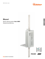
Manual
R67068.0002 - 1
Encoders with
PROFIBUS interface

Table of Contents Kübler Group
2 - EN HB Profibus Interface - R67068.0002 - 01
Table of Contents
1 Document ........................................................................................................................ 4
2 General Information........................................................................................................ 5
2.1 Target Group........................................................................................................... 5
2.2 Symbols used / Warnings and Safety instructions.................................................. 5
2.3 Transport / Storage ................................................................................................. 6
3 Product Description ....................................................................................................... 7
3.1 Technical Data Sendix 58xx ................................................................................... 7
3.2 Technical Data Sendix 70xx ................................................................................... 8
3.3 PROFIBUS Interface Description............................................................................ 9
3.4 Supported Standards and Protocols ....................................................................... 9
4 Installation....................................................................................................................... 11
4.1 Electrical Installation ............................................................................................... 11
4.1.1 General Information for the Connection.................................................... 11
4.1.2 Terminal Assignment 58xx........................................................................ 11
4.1.3 Terminal Assignment 70xx........................................................................ 13
4.1.4 Termination ............................................................................................... 14
4.1.5 Network Topology ..................................................................................... 15
5 Commissioning and Operation ..................................................................................... 16
5.1 Function and Status LED ........................................................................................ 16
5.2 Quick Start Guide.................................................................................................... 17
5.2.1 Default Settings......................................................................................... 17
5.2.2 Configuring the Modules ........................................................................... 19
5.3 Protocol Features.................................................................................................... 22
5.3.1 Device Profile V1.1.................................................................................... 22
5.3.2 The Requirements Profile ......................................................................... 23
5.3.3 Slave Mode ............................................................................................... 23
5.3.4 Encoder Start-up Phase on the PROFIBUS ............................................. 24
5.3.5 Configuration and Parameterizing ............................................................ 24
5.3.6 Protective Functions.................................................................................. 24
5.4 Configuration Parameters Description .................................................................... 24
5.4.1 Modules..................................................................................................... 24
5.4.2 Speed........................................................................................................ 28
5.4.3 Station Address......................................................................................... 29
5.4.4 Scaling ...................................................................................................... 31
5.4.5 Preset........................................................................................................ 32
5.5 Examples ................................................................................................................ 32
5.5.1 Changing the Station Address with SSA................................................... 32
5.5.2 Performing a Preset .................................................................................. 34
6 Annex............................................................................................................................... 36
6.1 Extended Diagnostic ............................................................................................... 36

Kübler Group Table of Contents
HB Profibus Interface - R67068.0002 - 01 EN - 3
6.2 Service Access Point (SAP).................................................................................... 37
6.3 Decimal / Hexadecimal conversion table ................................................................ 38
7 Contact ............................................................................................................................ 40
Glossary .......................................................................................................................... 41

1 Document Kübler Group
4 - EN HB Profibus Interface - R67068.0002 - 01
1 Document
This document is the English translation of the original German version.
Publisher Kübler Group, Fritz Kübler GmbH
Schubertstraße 47
78054 Villingen-Schwenningen
Germany
www.kuebler.com
Issue date 01/2020
Language version German is the original language
Copyright © 2020, Kübler Group, Fritz Kübler GmbH
Image sources Siemens - TIA Portal v14
Bihl + Wiedemann – PROFIBUS Master Simulator
Legal notices
All of the contents of this document are protected by the rights of use and copyrights of Fritz Kü-
bler GmbH. Any duplication, modification, further use and publications in other electronic or
printed media, as well as their publication in the Internet, even partially, is subject to the previ-
ous written authorization of Fritz Kübler GmbH.
The brand names and product brands mentioned in this document are trademarks or registered
trademarks of the respective titleholders.
Subject to errors and changes. The stated product features and technical data shall not consti-
tute any guarantee declaration.

Kübler Group 2 General Information
HB Profibus Interface - R67068.0002 - 01 EN - 5
2 General Information
Please read this document carefully before working with the product, mounting it
or starting it up.
2.1 Target Group
The device may only be planned, mounted, commissioned and serviced by persons having the
following qualifications and fulfilling the following conditions:
• Technical training.
• Briefing in the relevant safety guidelines.
• Constant access to this documentation.
• In case of electrical equipment for potentially explosive atmospheres, the specialized person-
nel needs knowledge about the ignition protection category concept.
• For facilities in potentially explosive atmospheres, the authorized person must comply with
the applicable country-specific regulations.
2.2 Symbols used / Warnings and Safety instructions
DANGER Classification:
This symbol, together with the signal word DANGER, warns against
immediately imminent threat to life and health of persons.
The non-compliance with this safety instruction will lead to death or
severe adverse health effects.
WARNING Classification:
This symbol, together with the signal word WARNING, warns against
a potential danger to life and health of persons.
The non-compliance with this safety instruction may lead to death or
severe adverse health effects.
CAUTION Classification:
This symbol, together with the signal word CAUTION, warns against
a potential danger for the health of persons.
The non-compliance with this safety instruction may lead to slight or
minor adverse health effects.

2 General Information Kübler Group
6 - EN HB Profibus Interface - R67068.0002 - 01
ATTENTION Classification:
The non-compliance with the ATTENTION note may lead to material
damage.
NOTICE Classification:
Additional information relating to the operation of the product, and
hints and recommendations for efficient and trouble-free operation.
2.3 Transport / Storage
Inspect the delivery immediately upon receipt for possible damages due to the transport. If you
do not mount the device immediately, store it preferably in its transport package.
Otherwise, make sure when storing the encoder that the shaft and the cable outlet are always
free from any load.
The encoder must be stored at a dry and dust-free location and in compliance with the technical
data, see chapter Technical Data.

Kübler Group 3 Product Description
HB Profibus Interface - R67068.0002 - 01 EN - 7
3 Product Description
3.1 Technical Data Sendix 58xx
Mechanical characteristics for the Sendix 58xx encoders
Maximum rotational speed
IP65 up to 70°C
IP65 up to Tmax
IP67 up to 70°C
IP67 up to Tmax
9000 min-1,
7000 min-1 (continuous operation)
7000 min-1,
4000 min-1 (continuous operation)
8000 min-1,
6000 min-1 (continuous operation)
6000 min-1,
3000 min-1 (continuous operation)
Starting torque (at 20°C)
IP65
IP67
<0.01 Nm
<0.05 Nm
Mass moment of inertia
Shaft version
Hollow shaft version
3.0 x 10⁻⁶ kgm2
7.5 x 10⁻⁶ kgm2 (MT)
6 x 10⁻⁶ kgm2 (ST)
Permissible shaft load
radial
axial
80 N
40 N
Protection level acc. to EN60529
Housing side
Shaft side
IP67
IP65, opt. IP67
Working temperature range -40°C ... +80°C
Materials
Shaft/hollow shaft
Flange
Housing
Stainless steel
Aluminum
Die-cast zinc
Shock resistance according to EN60068-2-27 2.500 m/s2, 6 ms
Vibration resistance according to EN60068-2-6 100 m/s2, 55 ... 2000 Hz
Electrical data for the Sendix 58xx encoders
Supply voltage 10 … 30 V DC
Current consumption (no load)
10…30VDC max. 110 mA
Supply voltage reverse polarity protection Yes

3 Product Description Kübler Group
8 - EN HB Profibus Interface - R67068.0002 - 01
Interface PROFIBUS PROFIBUS DP V0
Encoder profile Class 2
Encoder profile 3062 V1.1
Resolution
Singleturn (MUR)
Multiturn (NDR)
Total resolution (TMR)
Max. 28 bits (default 25 bits)
Max. 12 bits
Max. 28 bits (default 25 bits)
Type of connection 3 x M12 connector
3.2 Technical Data Sendix 70xx
Mechanical data for Sendix 70xx
Maximum rotational speed 6000min-1
Maximum angular acceleration 5x10⁵rad/s²
Operating/storage and
transport temperature range
-40°C...+60°C [-40°F…140°F]
Protection level according to EN 60529 IP67
Protection level according to NEMA 250 Type6
Installation height <2000m [6562ft]
Shock resistance according to EN/IEC60068-2-27 500m/s2, 11ms
Vibration resistance according to EN/IEC60068-2-6 5...2000Hz, 200m/s2
Electrical data for the Sendix 70xx encoders
Supply voltage
(depending on the variant)
5 V DC
5 … 30 V DC
10 … 30 V DC
Current consumption (no load)
5 V DC
5 … 30 V DC
10 … 30 V DC
max. 90 mA
max. 100 mA
max. 100 mA
Protection class according to EN61140 III (PELV)
EMC - Electromagnetic Compatibility
Relevant Standards EN55011 classB:2009/A1:2010
EN61326-1:2013
Interface PROFIBUS PROFIBUS DP V0
Encoder profile Class 2
Encoder profile 3062 V1.1
Resolution
Singleturn (MUR)
Multiturn (NDR)
Total resolution (TMR)
Max. 16 bits (default 13 bits)
Max. 12 bits
Max. 28 bits (default 25 bits)
Type of connection 3 x M12 connector

Kübler Group 3 Product Description
HB Profibus Interface - R67068.0002 - 01 EN - 9
3.3 PROFIBUS Interface Description
The main task of PROFIBUSDP is the cyclic transmission of process data from the control sys-
tem to the peripheral devices and vice versa. The access procedure uses the master-slave prin-
ciple. In polling operation, the master serves the slave devices assigned to it one after the other.
Data exchange is initiated by a query telegram and ended by an acknowledgment telegram
from the addressed slave. Thus every slave becomes active only upon request from the master.
This prevents simultaneous bus access. The hybrid access method of PROFIBUS allows com-
bined operation of several bus masters or mixed operation of PROFIBUSDP and
PROFIBUSFMS within a bus section.
Prerequisite for this is, however, the proper configuration of the bus system and the unambigu-
ous allocation of the slave devices to the masters. PROFIBUSDP distinguishes two master
types:
Class 1 master (DPM1): generally the automation system (PLC). It is in charge of the cyclic
transmission of the operating data and makes the user data available. The Class 1 master can
be addressed by a class 2 master that uses determined functions such as e. g. read or write
services via an initiate service.
Class 2 master (DPM2): the engineering tool that exclusively performs acyclic data transmis-
sion. The communication on the bus is based on whether a class 1 master or a class 2 master
initiates the communication.
NOTICE Direct access to the slaves is not allowed.
The functions are limited to slave support services such as e.g. the
readout of diagnostic information. Therefore, a class 2 master is un-
derstood as a programming or diagnostic device.
3.4 Supported Standards and Protocols
Class 1
Resolution 16 bits
(typ. singleturn)
Class 2
Resolution 32 bits
(typ. multiturn)
In/output consistent The encoder uses
1 input word and
1 output word, which are re-
spectively
consistently transmitted via
the bus.
The encoder uses
2 input words and
2 output words, which are re-
spectively consistently transmit-
ted via
the bus.
Input consistent The encoder uses
1 input word, which is consist-
ently transmitted via the bus.
The encoder uses
2 input words, which are respect-
ively consistently transmitted via
the bus.
For commissioning, the device requires the corresponding GSD data:

3 Product Description Kübler Group
10 - EN HB Profibus Interface - R67068.0002 - 01
Version Series GSD file
Singleturn 5858 KUEB5868ST.gsd
5878 KUEB5868ST.gsd
7058 KUEB7058.gsd
7078 KUEB7058.gsd
7158 KUEB7158.gsd
7178 KUEB7158.gsd
Multiturn 5868 KUEB5868.gsd
5888 KUEB5868.gsd
7068 KUEB7068.gsd
7088 KUEB7068.gsd
7168 KUEB7168.gsd
7188 KUEB7168.gsd

Kübler Group 4 Installation
HB Profibus Interface - R67068.0002 - 01 EN - 11
4 Installation
4.1 Electrical Installation
4.1.1 General Information for the Connection
ATTENTION Destruction of the device
Before connecting or disconnecting the signal cable, always discon-
nect the power supply and secure it against switching on again.
NOTICE Current limitation
Use a suitable external fuse for encoder protection, for a maximum
current of 500 mA.
NOTICE General safety instructions
Make sure that the whole plant remains switched off during the elec-
trical installation.
• Make sure that the operating voltage is switched on or off simultan-
eously for the device and the downstream device.
• Use a PELV supply voltage source according to EN60204-1 with
the proper operating voltage and the maximum permissible output
current.
4.1.2 Terminal Assignment 58xx
PROFIBUS connection M12 connector

4 Installation Kübler Group
12 - EN HB Profibus Interface - R67068.0002 - 01
Inter-
face
Type of
connec-
tion
Cable (isolate unused wires individually before
commissioning)
Connector
32Connector
Bus IN
Signal – PB_A – PB_B Shield
Pin 1 2 3 4 5
Bus OUT
Signal BUS_
VDC
PB_A BUS_
GND
PB_B Shield
Pin 1 2 3 4 5
Voltage supply
Signal +V – 0 V –
Pin 1 2 3 4
31Terminal strip
Bus IN
Signal B A 0 V + V
Pin 1 2 3 4
Bus OUT
Signal B A 0 V + V
Pin 7 8 5 6
PROFIBUS connection internal terminal strip
NOTICE Bus connection with separate voltage supply and PG screwed
fitting.
The bus cover must be removed to access to the internal terminal
strip.
• Unscrew the two bus cover screws and remove the bus cover from
the encoder.
• When re-tightening, take care to tighten the screws with a torque of
0.5 Nm.
Proceed as follows to connect the terminal strip :
a) Guide the incoming bus cable through the left screwed cable fitting and
b) connect the bus cable to terminal (B) and terminal (A). Apply the cable shield on the
cable fitting.
c) If there are further devices in the bus strand : Guide the continuing cable through the right
screwed cable fitting and connect it to terminal (B) and terminal (A).

Kübler Group 4 Installation
HB Profibus Interface - R67068.0002 - 01 EN - 13
Supply voltage
a) Guide the encoder supply voltage through the central screwed cable fitting and connect it
to the left terminals (+V) and terminal (0 V).
b) Apply the cable shield on the cable fitting.
NOTICE Duplicated signals
All signal inputs/outputs are duplicated and connected internally.
Abbreviation Designation Direction
B Profibus Out
A Profibus Out
0V 0 volt supply Out
+V +UB supply Out
0V 0 volt supply In
+V +UB supply In
B Profibus In
A Profibus In
4.1.3 Terminal Assignment 70xx
Cable
Signal 0V +V PB_A
IN
PB_B
IN
BUS_
GND
BUS_
VDC
PB_A
OUT
PB_B
OUT
Wire la-
beling
1 2 4 5 6 7 8 9 Shield

4 Installation Kübler Group
14 - EN HB Profibus Interface - R67068.0002 - 01
4.1.4 Termination
If a device is the last participant on the bus, the looped-through PROFIBUS must be terminated
actively at both ends with a bus termination resistor between A and B. For closed devices, the
termination must be specified in the order or provided by means of en external resistor. For
good signal transmission, PROFIBUS segments must be terminated with a bus termination. For
PROFIBUS RS485, the bus termination consists of three resistors.
The bus termination can be activated in the device or is prepared in the switch. If more than 32
participants are connected to the bus, repeaters must be used to connect the single bus seg-
ments. The terminating resistors between the lines are generally 220 Ω. 390 Ω resistors are
used between the reference potentials. Generally, the line termination is located in the cables or
in the respective PROFIBUS device, but it can also be installed separately. Network Topology
[}15]
Cable termination
Every bus segment must be terminated at both ends with a termination resistor. This cable ter-
mination is integrated in the RS485 repeaters, in the bus terminals and in the bus connectors,
and it can, if necessary, be activated. The component must be powered before the cable termin-
ation can be activated. The RS485 repeaters and the termination have their own power supply.
The RS485 transmission technology allows connecting at the maximum 32 devices per bus
segment (DTE's and Repeaters).
The maximum permissible cable length depends on the transmission speed and on the used
LAN cable. Network Topology [}15]
4.1.4.1 Termination with Sendix 58xx
The bus termination is set via hardware with the two DIP switches on the bus cover of the en-
coder rear side.
Both switches on: Termination active

Kübler Group 4 Installation
HB Profibus Interface - R67068.0002 - 01 EN - 15
NOTICE Bus termination with closed devices
For closed devices, the termination is either activated at the factory
or it must be provided externally with a resistor.
• Connect the terminating resistors with wires 8 and 9 (BUS_A) and
(BUS_B), and, for the active current lines, with wires 6 and 7.
4.1.5 Network Topology
All devices are connected in a bus structure (line). Up to 32 participants (master or slaves) can
be connected together in a segment. The bus is terminated with an active bus termination (ter-
mination resistors) at the beginning and at the end of every segment.
Both bus terminations must always be powered to ensure trouble-free operation. Termination
[}14]
The maximum line length depends on the transmission speed. The indicated line length can be
extended by using repeaters. We recommend not to use more than 3 repeaters.
Baud rate [kBit/s] 9.6 19.2 93.75 187.5 500 1500 12000
Range/segment 1,200 m 1,200 m 1,200 m 1,000 m 400 m 200 m 100 m

5 Commissioning and Operation Kübler Group
16 - EN HB Profibus Interface - R67068.0002 - 01
5 Commissioning and Operation
5.1 Function and Status LED
• Red LED = DIAG
• Yellow LED = BUS
• Green LED = PWR
Display LED Meaning Error cause Addition
PWR off No bus voltage present No voltage on
the device
Power supply defective
Check the voltage
supply
PWR on Bus voltage
present
Device ready for oper-
ation
Device in configuration
mode
BUS off Device waiting for con-
figuration or paramet-
erizing
GSD module must be
loaded and sent to the
encode
Observe the combin-
ation with the DIAG
LED.
BUS on Connection to the
master established
DATA_Exchange
mode
Process data
exchange
LED combinations during operation
Display LED Meaning Error cause Addition
PWR
+BUS on DATA_Exchange
mode
Device ready for pos-
ition data
exchange
Diag
flashing
Red LED flashing Temperature overrun
Sensor monitoring
Single-step error
Sensor LED current
monitoring
Connection to the
master
when connecting
+ additional error
cause
(Diagnostic header
requested)

Kübler Group 5 Commissioning and Operation
HB Profibus Interface - R67068.0002 - 01 EN - 17
Error display after powering
Display LED Meaning Error cause Addition
PWR
+Diag
flashing
Red LED flashing
1 x briefly
Pause 1.6 sec.
Data connection with
sensor faulty
Sensor faulty
Device must be sent
back to manufacturer
for check
PWR
+Diag
flashing
Red LED flashing
2 x briefly
Pause 1.6 sec.
Wrong
node address
Profibus short-circuit
Termination faulty
Check Profibus
General RESET - Switching the device on while pressing the SET key
Display LED Meaning Error cause Addition
PWR
+Diag
flashing
Short flashing of
the red LED
Diagnostic mode Device ready for dia-
gnostic
5.2 Quick Start Guide
5.2.1 Default Settings
Before a PROFIBUSDP system can be started up, all connected participants, including the
master system, must be assigned unique bus addresses. Only this way will an unambiguous
addressing be ensured on the bus. The addresses of the stations must first be assigned via the
bus.
The physical system settings then follow through the parameters set of the master. Besides the
master bus address, this set includes e. g. the baud rate, the timeout times and the number of
transmission repetitions. In addition to the master parameters set, a slave parameters set must
be saved for every slave to be activated. A data set contains the parameter assignment and
configuration data of the slave and the address pointer for the logical storage of the I/O data.
When the parameter sets are present, the master system begins to start up the slaves one after
the other, either upon user request or automatically.
The first so-called diagnostic cycles show which slave is present on the bus. Only the slaves
that send a proper feedback during the diagnostic cycle are subsequently parameterized during
the parameterizing cycles with the corresponding data stored in the master. After error-free exe-
cution, the configuration cycles compare the required configuration stored in the master with the
actual configuration of the slaves. After the last diagnostic cycle, every slave that did not detect
any error during the comparison is ready for operation.
Each of these slaves is automatically integrated by the master in the operating data exchange.
For diagnostic purposes, the master provides a diagnostic buffer for every slave. This buffer can
be read out by the user for other purposes. To make diagnostic easier, a group diagnostic field
is kept simultaneously. This field shows bit by bit whether it holds diagnostic data for a slave or
not.
The following parameters are factory-set:

5 Commissioning and Operation Kübler Group
18 - EN HB Profibus Interface - R67068.0002 - 01
Designa-
tion
Default Switch Product
Baud rate Automatic Not available
Node ad-
dress
63 –
without
SSA
Switch setting 0x3F Sendix 58xx
125 - with
SSA
For devices without removable bus
cover setting 0xFF (node address
via software change Set Slave Ad-
dress (SSA) [}31])
Sendix 70xx
Termina-
tion
Off Switch setting off Sendix 58xx
Name Default Byte Bit
Code sequence 0 = CW 9 0
Class 2 functionality 1 = Class 2 on 9 1
Scaling 1 = Scaling on 9 3
Scaling type 0 = Standard (MUR + TMR) 9 7
Scaling parameter MUR MUR = 8192 (13 bits) 10 … 13 0 … 7
Scaling parameter TMR TMR = 33554432 (25 bits) 14 … 17 0 … 7
Resetting to factory settings
The original standard values (default values at delivery) can be reset by pressing the SET key
on the rear side when switching on (parameters restoration).

Kübler Group 5 Commissioning and Operation
HB Profibus Interface - R67068.0002 - 01 EN - 19
NOTICE Reset via the SET key
Note that, for devices with external SET key, all programmed para-
meters are lost (except the station address, which has been assigned
by SSA). See Set Slave Address (SSA) [}31].
A reset with the SET key is only possible for devices with external
SET key.
Performing an external position reset:
a) Switch the encoder off.
b) When switching it back on, hold the SET key pressed for about 3 seconds, until the DIAG
LED flashes.
c) Switch the device off again.
ðWhen switching it on again, all values will be reset to the default settings.
If errors occurred during the programming of the objects, and if these parameters are saved in
the EPROM, addressing the encoder will not be possible when switching it on the next time.
This error can only be corrected by a general Reset of the encoder.
Also refer to
2Extended Diagnostic [}36]
5.2.2 Configuring the Modules
To be able to perform a general parameterizing of the device, the corresponding GSD file must
be selected and implemented first (e.g. KUEB7068.GSD). It can be found on the Kübler web
page of the concerned product.
The respective software allows including the GSD files.

5 Commissioning and Operation Kübler Group
20 - EN HB Profibus Interface - R67068.0002 - 01
Then a Module of the GSD file must be selected for the configuration.
8 different modules are available :
• Universal module
• 32-bit input/output, consistent
• 32-bit input, consistent
• 16-bit input/output, consistent
• 16-bit input, consistent
• MUR = 13 bits and TMR = 25 bits (input/output, consistent)
/