Page is loading ...


CAUTION
RISK OF ELECTRIC SHOCK
DO NOT OPEN
CAUTION: TO REDUCE THE RISK OF ELECTRIC SHOCK,
DO NOT REMOVE COVER (OR BACK)
NO USER-SERVICEABLE PARTS INSIDE
REFER SERVICING TO QUALIFIED SERVICE PERSONNEL
The lightning flash with arrowhead symbol within an equilateral triangle is
intended to alert the user to the presence of uninsulated “dangerous voltage”
within the product’s enclosure that may be of sufficient magnitude to constitute
a risk of electric shock to persons.
The exclamation point within an equilateral triangle is intended to alert the user
to the presence of important operating and maintenance (servicing) instructions
in the literature accompanying the product.
WARNING
TO REDUCE THE RISK OF FIRE OR ELECTRIC SHOCK,
DO NOT EXPOSE THIS PRODUCT TO RAIN OR MOISTURE.
CAUTION:
TO PREVENT ELECTRIC SHOCK, MATCH WIDE BLADE OF PLUG
TO WIDE SLOT, FULLY INSERT.
ATTENTION:
POUR ÉVITER LES CHOC ÉLECTRIQUES, INTRODUIRE LA
LAME LA PLUS LARGE DE LA FICHE DANS LA BORNE CORRESPONDANTE
DE LA PRISE ET POUSSER JUSQU’AU FOND.
NOTE TO CATV SYSTEM INSTALLER:
This reminder is provided to call the CATV (Cable-TV) system installer’s attention to Section 820-40 of the
NEC which provides guidelines for proper grounding and, in particular, specifies that the cable ground
shall be connected to the grounding system of the building, as close to the point of cable entry as practical.
NOTE:
This equipment has been tested and found to
comply with the limits for a Class B digital device,
pursuant to Part 15 of the FCC Rules. These limits
are designed to provide reasonable protection
against harmful interference in a residential
installation. This equipment generates, uses and
can radiate radio frequency energy and, if not
installed and used in accordance with the
instructions, may cause harmful interference to
radio communications. However, there is no
guarantee that interference will not occur in a
particular installation. If this equipment does cause
harmful interference to radio or television
reception, which can be determined by tuning the
equipment off and on, the user is encouraged to try
to correct the interference by one or more of the
following measures:
- Reorient or relocate the receiving antenna.
- Increase the separation between the equipment
and receiver.
- Connect the equipment into an outlet on a circuit
different from that to which the receiver is
connected.
- Consult the dealer or an experienced radio/TV
technician for help.
NOTE:
Changes or modifications not expressly approved
by the party responsible for compliance could void
the user’s authority to operate the equipment.
IMPORTANT SAFETY
INSTRUCTIONS
READ BEFORE OPERATING EQUIPMENT
This product was designed and manufactured to
meet strict quality and safety standards. There are,
however, some installation and operation
precautions which you should be particularly
aware of.
1. Read Instructions – All the safety and
operating instructions should be read before
the product is operated.
2. Retain Instructions – The safety and operating
instructions should be retained for future
reference.
3. Heed Warnings – All warnings on the product
and in the operating instructions should be
adhered to.
4. Follow Instructions – All operating and use
instructions should be followed.
5. Cleaning – Unplug this product from the wall
outlet before cleaning. Do not use liquid
cleaners or aerosol cleaners. Use a damp
cloth for cleaning.
6. Attachments – Do not use attachments not
recommended by the product manufacturer
as they may cause hazards.
7. Water and Moisture – Do not use this product
near water-for example, near a bath tub, wash
bowl, kitchen sink, or laundry tub, in a wet
basement, or near a swimming pool, and the
like.
8. Accessories – Do not place this product on an
unstable cart, stand, tripod, bracket, or table.
The product may fall, causing serious injury to
a child or adult, and serious damage to the
product. Use only with a cart, stand, tripod,
bracket, or table recommended by the
manufacturer, or sold with the product. Any
mounting of the product should follow the
manufacturer’s instructions, and should use a
mounting accessory recommended by the
manufacturer.
9. A product and cart combination should be
moved with care. Quick stops, excessive
force, and uneven surfaces may cause the
product and cart combination to overturn.
10. Ventilation – Slots and openings in the cabinet
are provided for ventilation and to ensure
reliable operation of the product and to protect
it from overheating, and these openings must
not be blocked or covered. The openings
should never be blocked by placing the
product on a bed, sofa, rug, or other similar
surface. This product should not be placed in
a built-in installation such as a bookcase or
rack unless proper ventilation is provided or
the manufacturer’s instructions have been
adhered to.
11. Power Sources – This product should be
operated only from the type of power source
indicated on the marking label. If you are not
sure of the type of power supply to your home,
consult your product dealer or local power
company. For products intended to operate
from battery power, or other sources, refer to
the operating instructions.
Only for USA, CANADA
04.8.26, 4:38 PMPage 1
Downloaded from www.Manualslib.com manuals search engine
Downloaded From DvDPlayer-Manual.com Marantz Manuals

12. Grounding or Polarization – This product may
be equipped with a polarized alternating-
current line plug (a plug having one blade
wider than the other). This plug will fit into the
power outlet only one way. This is a safety
feature. If you are unable to insert the plug
fully into the outlet, try reversing the plug. If the
plug should still fail to fit, contact your
electrician to replace your obsolete outlet. Do
not defeat the safety purpose of the polarized
plug.
AC POLARIZED PLUG
13. Power-Cord Protection – Power-supply cords
should be routed so that they are not likely to
be walked on or pinched by items placed upon
or against them, paying particular attention to
cords at plugs, convenience receptacles, and
the point where they exit from the product.
14. Protective Attachment Plug – The product is
equipped with an attachment plug having
overload protection. This is a safety feature.
See Instruction Manual for replacement or
resetting of protective device. If replacement
of the plug is required, be sure the service
technician has used a replacement plug
specified by the manufacturer that has the
same overload protection as the original plug.
15. Outdoor Antenna Grounding – If an outside
antenna or cable system is connected to the
product, be sure the antenna or cable system
is grounded so as to provide some protection
against voltage surges and built-up static
charges. Article 810 of the National Electrical
Code, ANSI/NFPA 70, provides information
with regard to proper grounding of the mast
and supporting structure, grounding of the
lead-in wire to an antenna discharge unit, size
of grounding conductors, location of antenna-
discharge unit, connection to grounding
electrodes, and requirements for the
grounding electrode. See Figure 1.
16. Lightning – For added protection for this
product during a lightning storm, or when it is
left unattended and unused for long periods of
time, unplug it from the wall outlet and
disconnect the antenna or cable system. This
will prevent damage to the product due to
lightning and power-line surges.
17. Power Lines – An outside antenna system
should not be located in the vicinity of
overhead power lines or other electric light or
power circuits, or where it can fall into such
power lines or circuits. When installing an
outside antenna system, extreme care should
be taken to keep from touching such power
lines or circuits as contact with them might be
fatal.
18. Overloading – Do not overload wall outlets,
extension cords, or integral convenience
receptacles as this can result in a risk of fire or
electric shock.
19. Object and Liquid Entry – Never push objects
of any kind into this product through openings
as they may touch dangerous voltage points
or short-out parts that could result in a fire or
electric shock. Never spill liquid of any kind on
the product.
20. Servicing – Do not attempt to service this
product yourself as opening or removing
covers may expose you to dangerous voltage
or other hazards. Refer all servicing to
qualified service personnel.
21. Damage Requiring Service – Unplug this
product from the wall outlet and refer servicing
to qualified service personnel under the
following conditions:
a. When the power-supply cord or plug is
damaged.
b. If liquid has been spilled, or objects have
fallen into the product.
c. If the product has been exposed to rain or
water.
d. If the product does not operate normally by
following the operating instructions. Adjust
only those controls that are covered by the
operating instructions as an improper
adjustment of other controls may result in
damage and will often require extensive work
by a qualified technician to restore the product
to its normal operation.
e. If the product has been dropped or damaged
in any way, and
f. When the product exhibits a distinct change in
performance – this indicates a need for
service.
FIGURE 1
EXAMPLE OF ANTENNA GROUNDING AS PER
NATIONAL ELECTRICAL CODE, ANSI/NFPA 70
This Class B digital apparatus complies with
Canadian ICES-003.
Cet appareil numérique de la Classe B est conforme
à la norme NMB-003 du Canada.
NEC - NATIONAL ELECTRICAL CODE
ANTENNA
LEAD IN WIRE
GROUND
CLAMP
ANTENNA
DISCHARGE UNIT
(NEC SECTION 810-20)
GROUNDING CONDUCTORS
(NEC SECTION 810-21)
ELECTRIC
SERVICE
EQUIPMENT
GROUND CLAMPS POWER SERVICE GROUNDING
ELECTRODE SYSTEM
(NEC ART 250, PART H)
22. Replacement Parts – When replacement
parts are required, be sure the service
technician has used replacement parts
specified by the manufacturer or have the
same characteristics as the original part.
Unauthorized substitutions may result in fire,
electric shock, or other hazards.
23. Safety Check – Upon completion of any
service or repairs to this product, ask the
service technician to perform safety checks to
determine that the product is in proper
operating condition.
24. Wall or Ceiling Mounting – The product should
be mounted to a wall or ceiling only as
recommended by the manufacturer.
25. Heat – The product should be situated away
from heat sources such as radiators, heat
registers, stoves, or other products (including
amplifiers) that produce heat.
Only for USA, CANADA
04.8.26, 4:38 PMPage 2
Downloaded from www.Manualslib.com manuals search engine
Downloaded From DvDPlayer-Manual.com Marantz Manuals

ENGLISH
WARRANTY
For warranty information, contact your local Marantz
distributor.
RETAIN YOUR PURCHASE RECEIPT
Your purchase receipt is your permanent record of
a valuable purchase. It should be kept in a safe
place to be referred to as necessary for insurance
purposes or when corresponding with Marantz.
IMPORTANT
When seeking warranty service, it is the
responsibility of the consumer to establish proof
and date of purchase. Your purchase receipt or
invoice is adequate for such proof.
FRANÇAIS
GARANTIE
Pour des informations sur la garantie, contacter le
distributeur local Marantz.
CONSERVER L'ATTESTATION D'ACHAT
L'attestation d'achat est la preuve permanente
d'un achat de valeur. La conserver en lieu sur pour
s'y reporter aux fins d'obtention d'une couverture
d'assurance ou dans le cadre de correspondances
avec Marantz.
IMPORTANT
Pour l'obtention d'un service couvert par la
garantie, il incombe au client d'établir la preuve de
l'achat et d'en corroborer la date. Le reçu ou la
facture constituent des preuves suffisantes.
ESPAÑOL
GARANTIA
Para obtener información acerca de la garantia
póngase en contacto con su distribuidor Marantz.
GUARDE SU RECIBO DE COMPRA
Su recibo de compra es su prueba permanente de
haber adquirido un aparato de valor, Este recibo
deberá guardarlo en un lugar seguro y utilizarlo
como referencia cuando tenga que hacer uso del
seguro o se ponga en contacto con Marantz.
IMPORTANTE
Cuando solicite el servicio otorgado por la garantia
el usuario tiene la responsabilidad de demonstrar
cuando efectuó la compra. En este caso, su recibo
de compra será la prueba apropiada.
PORTUGUÊS
GARANTIA
Para informações sobre a garantia, contactar o
distribuidor Marantz local.
GUARDAR O RECIBO DE COMPRA
O recibo é o registo permanente da compra que fez.
Deve ser guardado num local seguro, para ser
apresentado em questões relacionadas com o
seguro ou para quando tiver de contactar a Marantz.
IMPORTANTE
Quando procurar assisténcia técnica ao abrigo da
garantia, é da responsabilidade do consumidor
estabelecer a prova e data de compra. O recibe é
prova adequada.
English
WARNINGS
-
Do not expose the equipment to rain or moisture.
- Do not remove the cover from the equipment.
-
Do not insert anything into the equipment through
the ventilation holes.
- Do not handle the mains lead with wet hands.
-
Do not cover the ventilation with any items such as
tablecloths, newspapers, curtains, etc.
-
No naked flame sources, such as lighted candles,
should be placed on the equipment.
-
When disposing of used batteries, please comply
with governmental regulations or environmental
public instruction’s rules that apply in your
country or area.
-
Do not place anything about 0.2 meter above the
top panel.
-
Make a space of about 0.2 meter around the unit.
Français
AVERTISSEMENTS
- Ne pas exposer l’appareil à la pluie ni à l’humi-
dité.
- Ne pas essayer de retirer le boîtier de l’appareil.
- Ne rien insérer dans l’appareil par les orifices de
ventilation.
- Ne pas manipuler le cordon d’alimentation avec
les mains mouillées.
- Ne pas recouvrir les ouïes de ventilation avec un
objet quelconque comme une nappe, un journal,
un rideau, etc.
- Ne placer aucune source de flamme nue,
comme une bougie allumée, sur l'appareil.
- Pour mettre au rebut les piles usées, respecter
les lois gouvernementales ou les règlements
officiels concernant l’environnement qui
s'appliquent à votre pays ou région.
- Ne placez aucun object à moins de 0,2 mètre
environ du panneau supérieur.
- Veiller à ce qu’aucun objet ne soit à moins de
0,2 mètre des côtés de l'appareil.
Español
ADVERTENCIAS
-
No exponga el equipo a la lluvia ni a la humedad.
- No extraiga la tapa del equipo.
- No introduzca nada en el interior del equipo a
través de los orificios de ventilación.
- No maneje el cable de alimentación con las
manos mojadas.
- No cubra la ventilación con objetos como man-
teles, periódicos, cortinas, etc.
- No deben colocarse sobre el equipo elementos
con fuego, por ejemplo velas encendidas.
- Cuando se eliminen baterías usadas, deben
cumplirse las reglamentaciones oficiales o las
normas de protección medioambiental aplica-
bles en su país o en su zona.
-
No ponga nada a menos de 0,2 metro por encima
del panel superior.
- Deje un espacio de unos 0,2 metro alrededor de
la unidad.
Português
ADVERTÊNCIAS
-Não exponha o equipamento à chuva nem à
humidade.
-Não retire a tampa do equipamento.
-Não atire nada para dentro do equipamento
através dos orificíos de ventilação.
-Não manuseie o cabo de alimentação com as
mãos molhadas.
-Não cobrir os orifícios de ventilação com objec-
tos tais como toalhas de mesa, jornais, cortinas,
etc.
-Não colocar chamas abertas tais como velas
acesas, sobre o aparelho.
- Ao deitar foras as pilhas usadas, favor observar
os regulamentos governamentais ou as regras
com respeito ao meio ambiente que se aplicam
no seu país ou área de residência.
- Deixar um espaço completamente livre de cerca
de 0,2 metro acima do painel superior.
- Deixar um espaço de cerca de 0,2 metro ao
redor do aparelho.
04.8.26, 4:38 PMPage 3
Downloaded from www.Manualslib.com manuals search engine
Downloaded From DvDPlayer-Manual.com Marantz Manuals

ENGLISH
1
TABLE OF CONTENTS
FOREWORD ............................................................................................................ 2
EQUIPMENT MAINS WORKING SETTING ....................................................................................... 2
COPYRIGHT ...................................................................................................................................... 2
PRECAUTIONS ....................................................................................................... 2
DESCRIPTION......................................................................................................... 2
FEATURES .............................................................................................................. 3
ACCESSORIES ....................................................................................................... 3
ABOUT DISCS ........................................................................................................ 3
PLAYABLE DISCS ............................................................................................................................. 3
NOT PLAYABLE DISCS ..................................................................................................................... 3
VIDEO FORMAT ................................................................................................................................ 3
ABOUT DVD DISCS .......................................................................................................................... 4
ABOUT VIDEO CDS .......................................................................................................................... 4
ABOUT AUDIO CD ............................................................................................................................ 4
ABOUT MP3/WMA ............................................................................................................................. 4
ADDITIONAL INFORMATION ................................................................................. 4
CONTROLS ON THE MAIN UNIT ........................................................................... 5
CONTROL BUTTON ON THE REMOTE CONTROL UNIT ..................................... 7
OPERATION OF REMOTE CONTROL UNIT .................................................................................... 9
PROGRAMMING THE REMOTE CONTROL UNIT ........................................................................... 9
CONNECTIONS..................................................................................................... 11
PRECAUTIONS CONCERNING CONNECTIONS .......................................................................... 11
CONNECTING 5.1/6.1CH SPEAKER SYSTEM SS2500 (OPTIONAL) .......................................... 11
PHANTOM SURROUND BACK SPEAKER (5.1/6.1CH SPEAKER SYSTEM SS2500) ................. 12
CONNECTING ANTENNA TERMINALS AND OTHER SPEAKERS .............................................. 13
CONNECTING VIDEO COMPONENTS ........................................................................................... 14
CONNECTING AUDIO COMPONENTS .......................................................................................... 15
SPEAKER SETUP ................................................................................................. 16
SPEAKER SIZE ............................................................................................................................... 16
SPEAKER DISTANCE ..................................................................................................................... 17
SPEAKER BALANCE (TEST TONE) ............................................................................................... 17
SPEAKER LEVEL ............................................................................................................................ 18
DEFAULT SETTING (EXCEPT THE DVD SETUP MENU) .............................................................. 18
BASIC OPERATIONS ........................................................................................... 19
SELECTING AN INPUT SOURCE ................................................................................................... 19
ADJUSTING THE MASTER VOLUME ............................................................................................. 19
ADJUST TONE CONTROL (BASS AND TREBLE) ......................................................................... 19
MUTING THE SOUND ...................................................................................................................... 19
SETTING THE SURROUND MODE ................................................................................................. 20
BASIC OPERATION (PLAYBACK) ....................................................................... 22
PREPARATION ................................................................................................................................ 22
PLAYING A DISC ............................................................................................................................. 22
TO PAUSE PLAYING ....................................................................................................................... 22
TO STOP PLAYING ......................................................................................................................... 23
DIRECT SEARCH ............................................................................................................................ 23
SKIP PLAY ....................................................................................................................................... 23
SEARCH PLAYING .......................................................................................................................... 24
GUI (GRAPHICAL USER INTERFACE) .......................................................................................... 24
DVD MENU ....................................................................................................................................... 24
PLAYING VCD DISCS WITH PBC FUNCTION ................................................................................ 25
PLAYING MP3/WMA ........................................................................................................................ 25
VIEWING JPEG ............................................................................................................................... 26
VARIOUS PLAYING FUNCTIONS ........................................................................ 27
SLOW PLAY ..................................................................................................................................... 27
STEP PLAY ...................................................................................................................................... 27
CHANGING ANGLES ...................................................................................................................... 27
ZOOM FUNCTION ........................................................................................................................... 27
CHANGING AUDIO ......................................................................................................................... 28
CHANGING SUBTITLE LANGUAGES ............................................................................................ 28
REPEAT PLAY ................................................................................................................................. 28
A-B REPEAT PLAY .......................................................................................................................... 29
RANDOM PLAY ............................................................................................................................... 30
PROGRAM PLAY ............................................................................................................................. 31
BASIC OPERATIONS (TUNER) ............................................................................ 32
LISTENING TO THE TUNER (TUNING MODE) ............................................................................... 32
PRESET MEMORY OPERATION .................................................................................................... 32
SELECTING PRESET CHANNEL ................................................................................................... 33
CLEARING PRESET CHANNEL ..................................................................................................... 33
OTHER OPERATIONS .......................................................................................... 34
NIGHT MODE ................................................................................................................................... 34
USING THE DIMMER FUNCTION ................................................................................................... 34
USING THE SLEEP TIMER .............................................................................................................. 34
ANALOG/DIGITAL (VCR / DSS MODE ONLY) ............................................................................... 34
LISTENING THROUGH HEADPHONES ......................................................................................... 34
DVD SETUP MENU OPERATION ......................................................................... 35
CONTENTS OF SETUP MENU ....................................................................................................... 35
OSD LANGUAGE ............................................................................................................................. 35
SUB-TITLE ....................................................................................................................................... 35
TV DISPLAY ..................................................................................................................................... 35
TV TYPE ........................................................................................................................................... 36
PARENTAL RATING ........................................................................................................................ 36
PASSWORD ..................................................................................................................................... 37
PROGRESSIVE SCAN VIDEO OUTPUT ......................................................................................... 37
DEFAULT SETUP (DVD SETUP MENU ONLY) ............................................................................... 37
TROUBLE SHOOTING .......................................................................................... 38
MAINTENANCE..................................................................................................... 38
04.8.26, 4:29 PMPage 1
Downloaded from www.Manualslib.com manuals search engine
Downloaded From DvDPlayer-Manual.com Marantz Manuals

ENGLISH
2
ER2500
ER2500
Volume
STANDBYSTANDBY PHONESPHONES
DOWN-VOL-UPDOWN-VOL-UPFUNCTIONFUNCTIONSTOPSTOPPLAY/IIPAUSEPLAY/IIPAUSE
ER2500ER2500
OPEN/CLOSEOPEN/CLOSE
POWER
ON/STANDBYON/STANDBY
P.SCAN
EX
V CD MP3
DVD A.
PRGM
TITLE TRK CHP
DIGITALPCM5 STEREO ANALOG SL EEP
RANDOM
MUTE
STEREO
RDS
Tuned ALL AB PRESET
dB
kHz
MHz
FOREWORD
This section must be read before any connection is
made to the mains supply.
The model name notation in this guide is
classified as follow.
• ER2500U is a product for USA, CANADA.
• ER2500S is a product for Asia.
EQUIPMENT MAINS WORKING SETTING
Your Marantz product has been prepared to
comply with the household power and safety
requirements that exist in your area.
ER2500U can be powered by 120V AC only.
ER2500S can be powered by 230V AC only.
COPYRIGHT
Recording and playback of any material may
require consent. For further information refer to the
following:
— Copyright Act 1956
— Dramatic and Musical Performers Act 1958
— Performers Protection Acts 1963 and 1972
— any subsequent statutory enactments and
orders
PRECAUTIONS
The following precautions should be taken when
operating the equipment.
GENERAL PRECAUTIONS
When siting the equipment ensure that:
— the ventilation holes are not covered;
— air is allowed to circulate freely around the
equipment
— it is on a vibration free-surface;
— it will not be exposed to interference from an
external source;
— it will not be exposed to excessive heat, cold,
moisture or dust;
— it will not be exposed to direct sunlight;
— it will not be exposed to electrostatic
discharges
Never place heavy objects on the equipment.
If a foreign body or water does enter the equipment,
contact your nearest dealer or service centre.
Do not pull out the plug by pulling on the mains lead,
hold the plug.
It is advisable when leaving the house, or during a
thunderstorm, to disconnect the equipment from the
mains supply.
CAUTIONS ON INSTALLATION
For heat dispersal, leave at least 8 inches (20 cm)
of space between the top, back and sides of this
unit and the wall or other components.
• Do not obstruct the ventilation holes.
8 ins.
(20cm)
or more
4 ins.
(10cm)
or more
4 ins.
(10cm)
or more
4 ins.
(10cm)
or more
•
Neo:6 offers a music mode to expand stereo
nonmatrix recordings into the five- or six-channel
layout, in a way which does not diminish the
subtlety and integrity of the original stereo
recording.
DTS-ES Extended Surround is a new multichannel
digital signal format developed by Digital Theater
Systems Inc. While offering high compatibility with
the conventional DTS Digital Surround format,
DTS-ES Extended Surround greatly improves the
360-degree surround impression and space
expression thanks to further expanded surround
signals. This format has been used professionally
in movie theaters since 1999.
In addition to the 5.1 surround channels (FL, FR, C,
SL, SR and LFE), DTS-ES Extended Surround
also offers the SB (Surround Back) channel for
surround playback with a total of 6.1 channels.
DTS-ES Extended Surround includes two signal
formats with different surround signal recording
methods, as DTS-ES Discrete 6.1 and DTS-ES
Matrix 6.1.
“DTS”, “DTS-ES” and “Neo:6” are trademarks of
Digital Theater Systems, Inc.
Dolby Digital identifies the use of Dolby Digital
audio coding for such consumer formats as DVD
and DTV. As with film sound, Dolby Digital can
provide up to five full-range channels for left,
center, and right screen channels, independent left
and right surround channels, and a sixth ( ".1")
channel for low-frequency effects.
DESCRIPTION
DTS was introduced in 1994 to provide 5.1 channels
of discrete digital audio into home theater systems.
DTS brings you premium quality discrete multichannel
digital sound to both movies and music.
DTS is a multichannel sound system designed to
create full range digital sound reproduction.
The no compromise DTS digital process sets the
standard of quality for cinema sound by delivering
an exact copy of the studio master recordings to
neighborhood and home theaters.
Now, every moviegoer can hear the sound exactly
as the moviemaker intended.
DTS can be enjoyed in the home for either movies
or music on of DVD’s, LD’s, and CD’s.
“DTS” and “DTS Digital Surround” are registered
trademarks of Digital Theater Systems, Inc.
The advantages of discrete multichannel systems
over matrix are well known.
But even in homes equipped for discrete
multichannel, there remains a need for high-quality
matrix decoding. This is because of the large library
of matrix surround motion pictures available on disc
and on VHS tape; and analog television broadcasts.
The typical matrix decoder of today derives a
center channel and a mono surround channel from
two-channel matrix stereo material. It is better than
a simple matrix in that it includes steering logic to
improve separation, but because of its mono,
band-limited surround it can be disappointing to
users accustomed to discrete multichannel.
Neo:6 offers several important improvements as
follow,
•
Neo:6 provides up to six full-band channels of
matrix decoding from stereo matrix material. Users
with 6.1 and 5.1 systems will derive six and five
separate channels, respectively, corresponding to
the standard home-theater speaker layouts.
•
Neo:6 technology allows various sound elements
within a channel or channels to be steered
separately, and in a way which follows naturally
from the original presentation.
04.8.26, 4:29 PMPage 2
Downloaded from www.Manualslib.com manuals search engine
Downloaded From DvDPlayer-Manual.com Marantz Manuals

ENGLISH
3
Dolby Surround Pro Logic
II
is an improved matrix
decoding technology that provides better spatiality
and directionality on Dolby Surround program
material; provides a convincing three-dimensional
soundfield on conventional stereo music
recordings; and is ideally suited to bring the
surround experience to automotive sound. While
conventional surround programming is fully
compatible with Dolby Surround Pro Logic
II
decoders, soundtracks will be able to be encoded
specifically to take full advantage of Pro Logic
II
playback, including separate left and right
surround channels. (Such material is also
compatible with conventional Pro Logic decoders.)
Dolby Digital EX creates six full-bandwidth output
channels from 5.1-channel sources. This is done
using a matrix decoder that derives three surround
channels from the two in the original recording.
For best results, Dolby Digital EX should be used
with movies soundtracks recorded with Dolby
Digital Surround EX.
About Dolby Pro Logic II x
Dolby Pro Logic II x technology delivers a natural
and immersing 6.1- or 7.1-channel listening
experience to the home theater environment. A
product of Dolby's expertise in surround sound and
matrix decoding technologies, Dolby Pro Logic II x
is a complete surround sound solution that
maximizes the entertainment experience from
stereo as well as 5.1-channel encoded sources.
Dolby Pro Logic II x is fully compatible with Dolby
Surround Pro Logic technology and can optimally
decode the thousands of commercially available
Dolby Surround encoded video cassettes and
television programs with enhanced depth and
spatiality. It can also process any high-quality
stereo or Advanced Resolution 5.1-channel music
content into a seamless 6.1- or 7.1-channel
listening experience.
Manufactured under license from Dolby Laboratories.
“Dolby”, “Pro Logic”, and the double-D symbol are
trademarks of Dolby Laboratories.
FEATURES
ER2500
6.1ch DVD Receiver
(5 speakers including phantom speaker for
surround back and passive subwoofer)
Easy speaker setting menu
Sleep timer
Play back DVD /VCD /CD-DA /CD-R /CD-RW /
MP3/WMA /S-VCD /DVD+R /DVD+RW /DVD-R
/DVD-RW(video mode) /JPEG photo data
10-bit/54 MHz Video DAC
24-bit/192 KHz Audio DAC
SS2500 (Optional)
5.1/6.1ch speaker system
ACCESSORIES
ER2500
Remote control unit x1
Batteries (AAA type) x2
FM antenna x1
AM antenna x1
AC power cord x1 (only for ER2500S)
AUDIO cable x1
VIDEO cable x1
User’s guide x1
Warranty card for USA x1 (only for ER2500U)
Warranty card for CANADA x1 (only for ER2500U)
SS2500 (Optional)
Front speakers (right and left) x 2
Center speaker x 1
Surround speakers (right and left) x2
Subwoofer x 1
Speaker cord
• 5m cord for front left (White) x 1
• 5m cord for front right (Red) x 1
• 5m cord for center (Green) x 1
• 5m cord for subwoofer (Purple) x 1
• 10m cord for surround left (Blue) x 1
• 10m cord for surround right (Gray) x 1
•10m separation cord for surround back
(Phantom) (Brown) x 1
Tray for center speaker x 1
Cushion for subwoofer x 4
Terminal cover x 5
ABOUT DISCS
PLAYABLE DISCS
DVD
DVD+R/DVD+RW
DVD-R/DVD-RW
Finalized DVD disc recorded in
the DVD video format.
Video CD (VCD) /
Super Video CD(SVCD)
Audio CD (CD-DA)
CD-R/CD-RW
Finalized CD-R and CD-RW
discs recorded in the CD-DA
format, MP3 format (☞ p4
“ABOUT MP3/WMA”) or Video-
CD format can be played with
the unit.
*
Finalize is the process to make a DVD+R/DVD+RW,
DVD-R/DVD-RW or CD-R/CD-RW playable for
players (not recorders)
*
Some discs may not be able to be played depending
on condition of the discs and recording software.
NOT PLAYABLE DISCS
•DVD discs whose region number is not “1” nor
“ALL”.
•DVD-ROM
•DVD-RAM
•DVD-Audio
•CD-ROM
•CDV
•CD-G
•CVD
•Super Audio CD
•CD Photo, etc.
Caution
Some copy-controlled CDs may not conform to
official CD standards. They are special discs
and may not play on the this unit.
VIDEO FORMAT
This unit can handle with MULTI, NTSC or PAL
format.
Caution
This unit cannot handle with NTSC4.43 and
SECAM formats.
SETTING PICTURE FORMAT
1.
Every time the NTSC/PAL button on the remote
is pressed, picture format changes in the
following order.
NTSCPAL MULTI
Caution
•
If wrong color or disordered picture appears in the
MULTI mode, switch the mode to NTSC or PAL.
•If a disc recorded in PAL(NTSC) is played in the
NTSC(PAL) mode, picture may be disordered.
04.8.26, 4:29 PMPage 3
Downloaded from www.Manualslib.com manuals search engine
Downloaded From DvDPlayer-Manual.com Marantz Manuals

ENGLISH
4
ABOUT AUDIO CD
STRUCTURE OF AUDIO CD
Audio CDs contain music tracks only.
You can play them in conventional style through a
stereo system, using the keys on the remote
control and/or front panel.
ABOUT MP3/WMA
MP3 is the compressed music file in MPEG1, Audio
Layer 3 format.
A WMA(Windows Media Audio) file is a Microsoft
audio compression technology. WMA offers double
the audio compression of the MP3 format.
Microsoft, Windows Media, and the
Windows Logo are trademarks or
registered trademarks of Microsoft
Corporation in both the United
States and other countries.
MP3/WMA PLAYBACK
•This player can play MP3/WMA discs recorded
in ISO9660 format.
•The player plays the files with “.mp3/.WMA”
extension only.
•The maximum file number in a disc is 650.
(Including the number of folders.)
•The maximum folder layer number is 8.
•When playing a MP3/WMA disc, it may take
more than 30 seconds depending on the number
of files and folder layer structure.
ABOUT DVD DISCS
MARKS ON PACKAGES
The marks listed below indicate contents in a disc.
Indicates the number of recorded
audio tracks.
Indicates the number of recorded
subtitle languages.
Indicates the number of recorded
angles.
Indicates the selectable aspect
ratios.
Indicates the region number of the
disc.
REGIONAL RESTRICTION CODES
(REGION NUMBER)
Regional restriction codes are built in to ER2500
player and DVD discs for each sales region. If the
regional code of the ER2500 player does not
match one of the regional codes of the DVD disc,
playback is not possible.
The region number can be found on the rear panel
of the ER2500 player. The illustration below shows
the regions and corresponding region numbers.
STRUCTURE OF DVD DISCS
Depending on the material on the disc (a movie,
video clips, a drama series, etc.), these discs may
have one or more Titles, and each Title may have
one or more Chapters. To make access easy and
convenient, your player lets you move between
Titles and between Chapters.
ABOUT VIDEO CDS
VARIATIONS OF VIDEO CD
•Video-CD Version 2.0
The Video-CD with PBC (Play Back Control :
Menu playback function) function. You can
choose or search a section to play with a menu
displayed on the TV screen. Also still pictures
can be displayed in higher quality.
•Video-CD Version 1.1
The video-CD without PBC function. It can play
video and audio by operation much like to the
ordinary audio-CD.
STRUCTURE OF VIDEO-CD DISCS
Depending on the material on the disc (a movie,
video clips, a drama series, etc.), these discs may
have one or more tracks, and tracks may have one
or more indexes, as indicated on the disc case. To
make access easy and convenient, your player lets
you move between tracks and between indexes.
4
2
2
16 : 9 LB
1
ALL
ADDITIONAL
INFORMATION
The glossy side shining like a rainbow is the front
side of the disc, and the side on which the label is
printed is the back.
Unlike conventional turntables for playing analog
discs, the ER2500 reads the information recorded on
the disc from underneath without contacting it using
a beam of laser light. Therefore, the performance of
a compact disc will not degrade like conventional
analog records.
Handle discs carefully so as not to damage or
scratch the front side.
To protect the disc, avoid placing it in the
following locations:
•In direct sunlight or near a source of heat like a
heater.
•In a place which is damp or dirty.
•In a place which could be exposed to rain, such
as near a window.
Always keep the disc surface clean.
When cleaning the disc surface, always be sure to
use a special compact disc cleaner and wipe as
shown below.
•Do not use conventional record cleaner for
analog records, as this will adversely affect the
disc surface.
Store discs properly by placing them in their
disc cases.
04.8.26, 4:29 PMPage 4
Downloaded from www.Manualslib.com manuals search engine
Downloaded From DvDPlayer-Manual.com Marantz Manuals

ENGLISH
5
•Do not attach a piece of paper or sticker on the
label side of disc. When a disc has a piece of
plastic tape or rental DVD/CD label with paste
protruded from the edge or when a disc has a
trace of such a sticky object, do not attempt to
play the disc. If such a disc is played on the
DVD player, impossibility of taking out the disc
or other malfunction may result.
•Do not use a disc with a special shape.
Do not attempt to play a disc with a special
shape such as a heart-shaped disc or octagonal
disc. Otherwise the equipment malfunction may
result.
CONTROLS ON THE MAIN UNIT
FRONT PANEL
z
POWER ON / STANDBY button
•Press to turn power ON and press again to
switch to STANDBY mode.
xOPEN/CLOSE button
•Press this button to open and close the disc tray.
cDisc tray
vMaster volume indication
•This indication shows volume status of the unit.
8dB 1 time shift the light up LED position.
b2PLAY/ ; PAUSE button
•
In DVD mode, press this button to start playback.
•
In DVD mode, press this button to pause playback.
n9 STOP button
•
In DVD mode, press this button to stop playback.
mFUNCTION button
•Press this button to select the input function.
Pressing this button to change the function as
follows:
DVD
TUNER (FM/AM)
TV
VCR
DSS
,
VOLUME UP / DOWN
buttons
•These buttons are used to change the master
volume for listening. Press the up button to
increase and the down button to decrease the
volume.
.PHONES jack
•For connecting stereo headphones. When the
headphones are connected to this jack, the
speaker sound is turned off and the surround
mode be changed to stereo mode.
⁄0 Display
•When the unit is on, the current status of the unit
is displayed.
⁄1 STANDBY indicator
•The indicator lights GREEN when power is ON,
and lights RED when in STANDBY mode.
⁄2 Infrared sensor
•
The infrared signal from the remote control enters
the unit through this sensor.
Volume
STANDBYSTANDBY PHONESPHONES
DOWN-VOL-UPDOWN-VOL-UPFUNCTIONFUNCTIONSTOPSTOPPLAY/IIPAUSEPLAY/IIPAUSE
ER2500
OPEN/CLOSE
POWER
ON/STANDBY
10 911
1 2 4 5 6 83 7
12
04.8.26, 4:29 PMPage 5
Downloaded from www.Manualslib.com manuals search engine
Downloaded From DvDPlayer-Manual.com Marantz Manuals

ENGLISH
6
DISPLAY
aIndicates current disc format.
sP.SCAN indicates progressive scan mode.
dIndicates current title number.
fIndicates current track number.
gIndicates current chapter number.
hST indicates in the tuner mode.
jDisplays current status or time.
kIlluminates when a station is tuned.
lIlluminates during all track repeat playback.
¡0 Illuminates during repeat playback.
¡1 Illuminates when PRESET mode is selected.
¡2 Illuminates during mute.
¡3
PROG. indicates programmed playback is active.
¡4 Speaker icons.
¡5 Illuminates when SLEEP TIMER is set.
¡6 Illuminates during shuffle playback.
¡7
Illuminates when an analog source is selected.
¡8 Illuminates when a digital source is selected.
¡9 Type of audio signal.
™0 Surround mode.
™1 Indicates encoding audio format.
™2 Operating status indicator.
REAR PANEL
GNDGND
AUDIOAUDIO
COMPONENTCOMPONENT
VIDEO OUTVIDEO OUT
VIDEOVIDEO
VIDEOVIDEOS-VIDEOS-VIDEODSSDSSVCRVCR
DIGITALDIGITAL
OPTICAL OUTOPTICAL OUT
ININ
DVDDVD
ONLYONLY
MONITOR OUTMONITOR OUT
AMAM
ININININOUTOUT
YY
VCRVCR
CC
RR
/P/P
RR
CC
BB
/P/P
BB
DSSDSS
LL
RR
FMFM
(75(75
ΩΩ
))
ANTENNAANTENNA
SUBSUB
WOOFERWOOFER
PRE OUTPRE OUT
FRONTFRONTCENTERCENTER
SPEAKER SYSTEMS(6-16 OHMS)SPEAKER SYSTEMS(6-16 OHMS)
WOOFERWOOFER
SUBSUB
CENTERCENTER
AC INAC IN
SURROUND BACKSURROUND BACK
SURROUNDSURROUND
LLRRLLRR
RRLL
TV AUDIO INTV AUDIO IN
F G IH JC D E
N M
KA
OP L
B
ACENTER, SURROUND L/R
and SUBWOOFER speaker
terminals
•Connect the center, surround left and right,
passive subwoofer speaker cord of center,
surround L/R and subwoofer channels,
observing the and polarity of the cord and
terminals.
B
FRONT L/R speaker terminals
•Connect the front left and right speaker cord of
front channel, observing the and polarity
of the cord and terminals.
C
Digital output jack (Optical)
•The DVD, CD signals during playback are output
digitally from this optical jack.
DVCR digital audio input jack
(Coaxial)
•
Connect to the digital audio output jack of a VCR.
EDSS digital audio input jack
(Optical)
•
Connect to the digital audio output jack of a DSS.
F
S-Video output jack
(DVD mode only)
•Connect to the s-video input jack of a monitor or
TV input.
G
Video output jack
•Connect to the composite video input jack of a
monitor or TV input.
H
Component video output jacks
(DVD mode only)
•Connect to the component video input jacks of
TV.
I
VCR IN/OUT jacks
•Connect the IN jacks to the output jacks of VCR
and the OUT jacks to VCR input jacks.
J
DSS IN jacks
•Connect the IN jacks to the output jacks of DSS.
K
FM antenna terminal (75 ohms)
•Connect an external FM antenna with a coaxial
cable, or a cable network FM source.
LAM antenna and ground
terminals
•Connect the supplied AM loop antenna. Use the
terminals marked “AM” and “GND”. The supplied
AM loop antenna will provide good AM reception
in most areas. Position the loop antenna until
you hear the best reception.
M
TV AUDIO IN jack
•
Connect the IN jack to the audio output jack of TV.
N
SUB WOOFER PRE OUT jack
•Connect to a component speaker input of an
active subwoofer.
O
SURROUND BACK CENTER
speaker terminals
•
Connect the separation cord supplied (Brown)
for Surround Back (Phantom) observing the
and polarity of the cord and terminals.
•If you use other 6.1ch speaker system than
SS2500, connect the surround back center
speaker cord of surround back center channel.
P
AC power cable (ER2500U)
•Connect to an AC power outlet.
This unit has to be powered by 120V AC only.
Q
AC IN (ER2500S)
•Connect to supplied an AC cable, and connect
to an AC power outlet.
ER2500S unit has to be powered by 230V AC
only.
¡5¡7¡8¡9™0™1™2
¡6
dsaafghkl¡0¡1 ¡4
¡2 ¡3
j
ER2500U
GND
AUDIO
COMPONENT
VIDEO OUT
VIDEO
VIDEOS-VIDEODSSVCR
DIGITAL
OPTICAL OUT
AV EURO
IN
DVD
ONLY
MONITOR OUT
AM
ININOUT
Y
VCR
C
R
/P
R
C
B
/P
B
DSS
L
R
FM
(75
Ω
)
ANTENNA
SUB
WOOFER
PRE OUT
FRONTCENTERCENTER
SPEAKER SYSTEMS(6-16 OHMSSPEAKER SYSTEMS(6-16 OHMS)
WOOFERWOOFER
SUBSUB
CENTERCENTER
AC INAC IN
SURROUND BACKSURROUND BACK
SURROUNDSURROUND
LRLLRR
Q
ER2500S
04.8.26, 4:29 PMPage 6
Downloaded from www.Manualslib.com manuals search engine
Downloaded From DvDPlayer-Manual.com Marantz Manuals

ENGLISH
7
NIGHTNIGHTTONETONE
T.TONET.TONE SPK SETSPK SETNTSC/PALNTSC/PAL
1/ALL1/ALL A-BA-B RANDOMRANDOM CLRCLRPRGPRG
ZOOMZOOMANGLEANGLEAUDIOAUDIOS.TITLES.TITLE
T.CLRT.CLR RDSRDS FM MODEFM MODE MEMORYMEMORY
TUNE PRESETTUNE PRESET BANDBAND TUNE MODETUNE MODE
REPEATREPEAT
RC2500ERRC2500ER
ENTERENTER
MENUMENU
TOP MENUTOP MENUDVD-SET UPDVD-SET UP
RETURNRETURN
DISPLAYDISPLAY
MUTEMUTE
VOLUMEVOLUME
DIMMERDIMMERSURROUNDSURROUND
00
998877
665544
332211
TV-CHTV-CH
TV-VOLTV-VOL
TV-INPUTTV-INPUTA/DA/DDSSDSSVCRVCR
TV POWERTV POWERTVTVTUNERTUNERDVDDVD
SLEEPSLEEPSTANDBY/ONSTANDBY/ON
111
5
16
212
13
14
15
17
18
4
3
8
7
9
6
19
10 20
CONTROL BUTTON ON THE REMOTE CONTROL UNIT
q STANDBY/ON button
•
Press to turn power ON and press again to switch
to STANDBY mode.
wFunction buttons
•
There are DVD, TUNER, TV, VCR, DSS buttons.
These buttons are used to select the source to
be played.
eA/D button
(VCR / DSS mode only)
•Press this button to switch between the analog
and digital inputs.
rNumeric (ten keypad) button
•These buttons are used to key in the track
number, program number, preset channel
number, password, etc directly.
tSURROUND button
•Press this button to select for surround mode.
The surround mode which can be select changes
with audio signals and speaker settings. (
☞
p20)
Select the appropriate surround mode according
to the program source.
yVOLUME + / – (up / down)
buttons
•These buttons are used to change the volume
for listening. Press the + button to increase and
the – button to decrease the volume.
uDISPLAY button
(DVD mode only)
•This button is used to display the playback
information during disc playback.
iDVD-SET UP button
•
In DVD mode,
this button is used to display the
setup menu (OSD) in stop mode.
oCursor ( , , , ) buttons
•These buttons are used to operate the MENU
functions.
: Moves the cursor left
: Moves the cursor right
: Moves the cursor up
: Moves the cursor down
!0 RETURN button
In DVD mode for DVD disc
•This button is used to exit menu of DVD disc.
In DVD mode for Video CD disc
•This button is used to return the menu screen
while playing VCD disc with PBC ON.
!1 SLEEP timer button
•
This button is used to set the sleep timer. Each
press of this button change the sleep time following
order.
10 → 20 → 30 → 40 → 50 → 60 → 70 → 80 → 90
→ 100 → 110 → 120 → OFF (original display)
•The setting time passes, the power is turned off.
!2 TV POWER button*
•
Press to turn power ON and press again to switch
standby for TV.
!3 TV-INPUT button*
•
Press this button to select for TV side input function.
!4 TV-VOL ( / ) button*
•These button are used to change the TV volume
level.
!5 TV-CH ( / ) button*
•
These button are used to change the TV channel.
*
These buttons can be programmed to use the
codes for your appliances of different brands
from build in data bank. Other buttons can
not be programmed.
!6 DIMMER button
•This button is used to select the dimmer on / off.
Repeatedly press the this button to select DIMM
ON and DIMM OFF. When you select DIMM ON,
the display is dimmed.
!7 MUTE button
•This button is used to mute the sound from the
speakers. When this button is pressed, the
speakers’ sound level is muted and “MUTE”
appears on the display. Press this button again
to cancel the muting function, and it can also be
cancelled by pressing the volume up or down
button.
!8 TOP MENU button
In DVD mode for DVD disc
•Press this button to display the title screen in a
DVD disc. This button is to show the title menu
screen of DVD discs that contain multiple titles.
In DVD mode for Video CD disc
•
This button is used to change PBC on / off in DVD
mode.
!9 ENTER button
•This button is used to enter the selected MENU
function.
@0 MENU button
•Press this button to display the menu in a DVD
disc menu.
04.8.26, 4:29 PMPage 7
Downloaded from www.Manualslib.com manuals search engine
Downloaded From DvDPlayer-Manual.com Marantz Manuals

ENGLISH
8
@3 . /RDS button
In DVD mode
•Press this button for slow forward playback
chapter.
In TUNER mode
•This button is unavailable.
@4 , /T.CLR button
In DVD mode
•
Press this button for slow backward playback
chapter.
In TUNER mode
•In Preset mode, press this button to clear preset
memory.
@5 3 (Play) /BAND button
In DVD mode
•In DVD or CD mode, press this button to start
playback.
In TUNER mode
•Press this button to select FM or AM.
@6 TUNE MODE button
•In TUNER mode, press this button to select
between the Tuning mode and Preset mode.
@7 7 (Stop) /FM MODE button
In DVD mode
•Press this button to stop playback.
In TUNER mode
•
In Tuning mode, press this button to select stereo
or monoral mode, while listening to FM broadcasts.
@8 8 (Pause) /MEMORY button
In DVD mode
•In DVD or CD mode, press this button to pause
playback.
In TUNER mode
•
Press this button to memory the preset channels.
•
Press this button to scan the preset channels
automatically for 2 seconds or more.
@9
AUDIO
button
•
In DVD mode, press this button to select an audio.
#0
S.TITLE
button
•
In DVD mode, press this button to select a subtitle
language.
#1
ANGLE button
•
If the playing DVD disc contains multi-angle video,
press this button to change the angle.
#2
ZOOM button
•
Press this button to enlarge picture. (This function
may be disabled depending on discs.)
#3 REPEAT 1/ALL button
•In DVD mode, press for repeat play during
playback. Each time the button is pressed, the
mode changes in the following sequence:
1-chapter(track) repeat
Title(all track) repeat
Off
#4 PRG (Program) button
•
In DVD mode, press this button to program tracks
for program play in stop mode. (VCD/CD)
#5 NTSC/PAL button
•Press this button to select for the picture format
PAL, NTSC, or MULTI to mach your TV.
#6 T.TONE button
•This button is used to output the test tone.
Note:
The maximum test tone level is depending on the
volume level.
#7 SPK SET button
•Press this button to select for speaker size,
speaker distance, speaker level by pressing the
cursor buttons.
#8 RANDOM button
•Press for random play to play the tracks in a
random sequence. (VCD/CD/MP3/WMA/JPEG)
#9 CLR (Clear) button
•Press this button to cancel a programmed track.
(VCD/CD)
$0 NIGHT button
•
Pressing this button prevents the Dolby Digital
signal from playback at a loud voice. This function
reduces the voice by 1/3 to 1/4 at maximum.
Thus, it eliminates the occurrence of an abruptly
loud voice at night.
The Night Mode is effective the Dolby Digital only
when the signal is entered through the DVD,
VCR, DSS, digital input jack and it compresses
the dynamic range.
$1 TONE button
•Press this button to select for the tone (BASS
or TREBLE). To adjust the tone level by
pressing the volume buttons.
OFFBASS TRE
$2 REPEAT A-B button
•
In DVD mode, used to set the starting and stopping
points of a passage for repeated playback.
ENTERENTER
MENUMENU
TOP MENUTOP MENUDVD-SET UPDVD-SET UP
RETURNRETURN
DISPLAYDISPLAY
MUTEMUTE
VOLUMEVOLUME
DIMMERDIMMERSURROUNDSURROUND
00
998877
665544
332211
TV-CHTV-CH
TV-VOLTV-VOL
TV-INPUTTV-INPUTA/DA/DDSSDSSVCRVCR
TV POWERTV POWERTVTVTUNERTUNERDVDDVD
SLEEPSLEEPSTANDBY/ONSTANDBY/ON
RC2500ERRC2500ER
NIGHTNIGHTTONETONE
T.TONET.TONE SPK SETSPK SET
1/ALL1/ALL A-BA-B RANDOMRANDOM CLRCLRPRGPRG
ZOOMZOOMANGLEANGLEAUDIOAUDIOS.TITLES.TITLE
T.CLRT.CLR RDSRDS FM MODEFM MODE MEMORYMEMORY
TUNE PRESETTUNE PRESET BANDBAND TUNE MODETUNE MODE
REPEATREPEAT
NTSC/PALNTSC/PAL
30
23
29
32
31
24 28
27
25
2622
21
34
33 38
39
40
37
36
35
42
41
@1 ¢ button
•This button is used to skip to next chapter / track
on DVD/CD discs or increase the number on the
TUNER preset memory .
@2 4 button
•This button is used to skip to previous chapter /
track on DVD/CD discs or decrease the number
on the TUNER preset memory .
04.8.26, 4:29 PMPage 8
Downloaded from www.Manualslib.com manuals search engine
Downloaded From DvDPlayer-Manual.com Marantz Manuals

ENGLISH
9
OPERATION OF REMOTE CONTROL UNIT
1. REMOTE CONTROL
The distance between the transmitter of the remote
control unit and the IR SENSOR of the ER2500
should be less than about 5 meters. If the transmitter
is pointed to a direction other than the IR SENSOR
or if there is an obstacle between them, remote
control may not be possible.
Remote-controllable range
2. LOADING BATTERIES
The life of the batteries used with the remote control
unit is about 4 months with normal use. Also be sure
to replace batteries earlier when you notice that
they are getting weak.
1. Remove the back cover.
2. Insert the new batteries (AAA type) with
correct (+) and (–) polarity.
60°
Approx. 5 meters
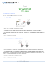
PROGRAMMING THE REMOTE CONTROL
UNIT
The remote control unit RC2500ER must be
programmed to use the codes for your appliances
of different brands. This is done by keying in a 3-
digit code or by scanning the codes until the correct
one is found. We recommend to using the 3-digit
code. This mode is faster and more reliable. The
code scanning method should be used only if you
cannot find the code for one of your appliances.
The codes are listed at the end of this book.
Important:
•
Use the remote control buttons for programming,
not the buttons of the receiver or other appliances.
•
Some codes may be not match your equipment.
In this case, your equipment cannot be controlled
with this remote controller.
•
If the battery life of remote controller is
lost, a
program code will be reset from a memory.
PROGRAMMING WITH THE 3-DIGIT CODE
NIGHT
NIGHT
TONE
TONE
T.TONE
T.TONE
SPK SET
SPK SET
NTSC/PAL
NTSC/PAL
1/ALL
1/ALL
A-B
A-B
RANDOM
RANDOM
CLR
CLR
PRG
PRG
ZOOM
ZOOM
ANGLE
ANGLE
AUDIO
AUDIO
S.TITLE
S.TITLE
T.CLR
T.CLR
RDS
RDS
FM MODE
FM MODE
MEMORY
MEMORY
TUNE PRESET
TUNE PRESET
BAND
BAND
TUNE MODE
TUNE MODE
REPEAT
REPEAT
RC2500ER
RC2500ER
ENTER
ENTER
MENU
MENU
TOP MENU
TOP MENU
DVD-SET UP
DVD-SET UP
RETURN
RETURN
DISPLAY
MUTE
VOLUME
DIMMERSURROUND
0
987
654
321
TV-CH
TV-VOL
TV-INPUTA/DDSSVCR
TV POWERTVTUNERDVD
SLEEPSTANDBY/ON
NIGHTTONE
T.TONE SPK SETNTSC/PAL
1/ALL A-B RANDOM CLRPRG
ZOOMANGLEAUDIOS.TITLE
T.CLR RDS FM MODE MEMORY
TUNE PRESET BAND TUNE MODE
REPEAT
RC2500ER
ENTER
MENU
TOP MENU
TOP MENU
DVD-SET UP
DVD-SET UP
RETURN
DISPLAY
DISPLAY
MUTE
MUTE
VOLUME
VOLUME
DIMMER
DIMMER
SURROUND
SURROUND
0
0
9
9
8
8
7
7
6
6
5
5
4
4
3
3
2
2
1
1
TV-CH
TV-CH
TV-VOL
TV-VOL
TV-INPUT
TV-INPUT
A/D
A/D
DSS
DSS
VCR
VCR
TV POWER
TV POWER
TV
TV
TUNER
TUNER
DVD
DVD
SLEEP
SLEEP
STANDBY/ON
STANDBY/ON
2
2
3
1.
Turn on the appliance which should be controlled.
2. Press and hold down the ENTER button and
press TV button until the indicator lamp blinks
twice.
3.
Press the 3-digit code for appliance. (code
table at the end of this book)
•If the 3-digit code is not pressed with 10
seconds, this programming function is
canceled.
4.
When the procedure is successful, the indicator
lamp will blink twice.
Note:
•
If the indicator lamp blinks in 1 second, program
code is wrong.
•If the indicator lamp did not blink twice, then
repeat steps 1 through 2 and try entering the
same code again.
3. Close until it clicks.
Notes:
• Do not mix alkaline and manganese batteries.
• Do not mix old and new batteries.
CAUTIONS ON BATTERIES
•Use “AAA” type batteries in this remote control
unit.
•If the remote control unit does not operate from
close to the main unit, replace the batteries with
new ones, even if less then a year has passed.
•
The included battery is only for verifying operation.
Replace it with a new battery as soon as possible.
•
When inserting the batteries, be careful to do so
in the proper direction, following the + and - marks
in the remote control unit’s battery compartment.
•To prevent damage or battery fluid leakage:
- Do not use a new battery with an old one.
- Do not use two different types of batteries.
- Do not short-circuit, disassemble, heat or
dispose of batteries in flames.
•Remove the batteries when not planning to use
the remote control unit for a long period of time.
•If the batteries should leak, carefully wipe off the
fluid from the inside of the battery compartment,
then insert new batteries.
•
When disposing of used batteries, please comply
with governmental regulations or environmental
public instruction’s rules that apply in your country
or area.
04.8.26, 4:29 PMPage 9
Downloaded from www.Manualslib.com manuals search engine
Downloaded From DvDPlayer-Manual.com Marantz Manuals

ENGLISH
10
SCANNING THE CODE TABLE
NIGHT
NIGHT
B-BOOST
B-BOOST
CLOCK
CLOCK
TIMER
TIMER
ROOM SET
ROOM SET
SPK SET
SPK SET
S.WOOFER
S.WOOFER
T.TONE
T.TONE
A/D
A/D
SET UP
SET UP
RDS
RDS
PTY
PTY
CLR
CLR
MODE
MODE
ZOOM
ZOOM
ANGLE
ANGLE
AUDIO
AUDIO
S.TITLE
S.TITLE
TUNE
TUNE
PRESET
PRESET
ENTER
ENTER
MENU
MENU
TOP MENU
TOP MENU
DVD-SET UP
DVD-SET UP
RETURN
RETURN
SURROUND
MUTE
VOLUME
DISPLAYSTEREO
0
9
87
654
321
TV-CH
TV-VOL
TV-INPUTSLEEPAMPVCR
TV POWERTVTUNERDVD
SOURCE
RC2400SR
RC2400SR
SYSTEM
NIGHT
B-BOOST
CLOCKTIMER
ROOM SET SPK SET
S.WOOFERT.TONE
A/D
SET UP
RDS PTY CLRMODE
ZOOMANGLEAUDIOS.TITLE
TUNE
PRESET
ENTER
MENU
TOP MENU
TOP MENU
DVD-SET UP
DVD-SET UP
RETURN
SURROUND
SURROUND
MUTE
MUTE
VOLUME
VOLUME
DISPLAY
DISPLAY
STEREO
STEREO
0
0
9
9
8
8
7
7
6
6
5
5
4
4
3
3
2
2
1
1
TV-CH
TV-CH
TV-VOL
TV-VOL
TV-INPUT
TV-INPUT
SLEEP
SLEEP
AMP
AMP
VCR
VCR
TV POWER
TV POWER
TV
TV
TUNER
TUNER
DVD
DVD
SOURCE
SOURCE
RC2400SR
SYSTEM
SYSTEM
2,5
23
1.
Turn on the appliance which should be controlled.
2. Press and hold down the ENTER button and
press TV button until the indicator lamp blinks
twice.
3.
Aim the remote control sensor at the appliance
and slowly pressing the cursor (3,4) button
until appliance turns off.
•If
the cursor (3,4) button
is not pressed
with 10 seconds, this programming function
is canceled.
4. Stop when the appliance turns off.
5. Press ENTER button once to lock in the code.
At this time, the indicator lamp will blink twice.
CHECKING THE CODE
NIGHT
NIGHT
B-BOOST
B-BOOST
CLOCK
CLOCK
TIMER
TIMER
ROOM SET
ROOM SET
SPK SET
SPK SET
S.WOOFER
S.WOOFER
T.TONE
T.TONE
A/D
A/D
SET UP
SET UP
RDS
RDS
PTY
PTY
CLR
CLR
MODE
MODE
ZOOM
ZOOM
ANGLE
ANGLE
AUDIO
AUDIO
S.TITLE
S.TITLE
TUNE
TUNE
PRESET
PRESET
ENTER
ENTER
MENU
MENU
TOP MENU
TOP MENU
DVD-SET UP
DVD-SET UP
RETURN
RETURN
SURROUND
MUTE
VOLUME
DISPLAYSTEREO
0
9
87
654
321
TV-CH
TV-VOL
TV-INPUTSLEEPAMPVCR
TV POWERTVTUNERDVD
SOURCE
RC2400SR
RC2400SR
SYSTEM
NIGHT
B-BOOST
CLOCKTIMER
ROOM SET SPK SET
S.WOOFERT.TONE
A/D
SET UP
RDS PTY CLRMODE
ZOOMANGLEAUDIOS.TITLE
TUNE
PRESET
ENTER
MENU
TOP MENU
TOP MENU
DVD-SET UP
DVD-SET UP
RETURN
SURROUND
SURROUND
MUTE
MUTE
VOLUME
VOLUME
DISPLAY
DISPLAY
STEREO
STEREO
0
0
9
9
8
8
7
7
6
6
5
5
4
4
3
3
2
2
1
1
TV-CH
TV-CH
TV-VOL
TV-VOL
TV-INPUT
TV-INPUT
SLEEP
SLEEP
AMP
AMP
VCR
VCR
TV POWER
TV POWER
TV
TV
TUNER
TUNER
DVD
DVD
SOURCE
SOURCE
RC2400SR
SYSTEM
SYSTEM
1
2
1
1. Press and hold down the ENTER button and
press TV button until the indicator lamp blinks
twice.
2. Press the DISPLAY button.
The indicator will blink twice.
3.
After 2 seconds, the indicator will blink according
to first, second and third digit for the current
setup code, count the indicator blinks (e.g. 3
blinks = 3) and write down the number.
Note:
•If a code digit is “0”, the indicator will blinks 10
times.
Once you have found and the codes for your various
appliances, you may want to write them down here.
TV
04.8.26, 4:29 PMPage 10
Downloaded from www.Manualslib.com manuals search engine
Downloaded From DvDPlayer-Manual.com Marantz Manuals

ENGLISH
11
Front left and right speakers
We recommend to set the front L and R speakers
with 45-60 degrees from the listening position.
Center speaker
We recommend to set the front line of the center
speaker with the front L/R speakers.
Surround left and right speakers include phantom
surround back speaker
Place the speakers right beside of the listening
position or a little backward.
Subwoofer
We recommend to use a subwoofer to have
maximum bass effect. Subwoofer bears only low
frequency range so you can place it vertically or
horizontally, anywhere in the room.
Note:
•
Pay special attention for the following speakers
placements.
Surround L and Surround R Speakers.
Place the Surround Speaker L (SS2500SL)
to your left side and the Surround R Speaker
(SS2500SR) to your right side. Do not
interchange left and right.
Center Speaker
Lay the Center Speaker(SS2500C) on the
tray attached as an accessory.
Subwoofer
CONNECTIONS
PRECAUTIONS CONCERNING
CONNECTIONS
•Use only a 120V AC power source for ER2500U,
and a 230V AC power source for ER2500S.
Using any other power source could cause a fire
or electric shock.
•Always grasp the power plug when unplugging
or plugging in the power cord.
•Complete all connections before plugging in the
power cord.
•Be sure to make a distinction between the left
(white) and right (red) audio cable plugs when
connecting them.
•When connecting this unit to other audio
equipment, read the operation manual for that
equipment carefully for details on how to make
the correct connections.
CONNECTING 5.1/6.1CH SPEAKER SYSTEM
SS2500 (OPTIONAL)
The 5.1/6.1ch speaker system SS2500 consists of
the following speakers. (See the labels of each
speakers.)
• Front Speaker L/R (SS2500F) x 2
• Center Speaker (SS2500C) x 1
• Surround L Speaker (SS2500SL) x 1
• Surround R Speaker (SS2500SR) x 1
• Subwoofer (SS2500SW) x 1
1.
Locate those speakers as shown below.
2.
Connect Speaker to Unit. (☞ p12)
Connect the speakers to the corresponding
speaker terminals of the ER2500 using colored
cords supplied.
CONNECTING SPEAKER CORD TO UNIT
1. Push the terminal lever in the direction of the
arrow, and keep this condition.
2. Insert the bare part of the cord into the hole in
the side of each terminal.
3. Put the terminal lever back, and make sure it
is fastened securely by pulling the cord lightly.
1. 2. 3.
CONNECTING SPEAKER CORD TO 5.1/
6.1CH SPEAKER SYSTEM SS2500
1. Loosen the knob by turning counterclockwise.
2. Insert the bare part of the cord into the hole in
the side of each terminal.
3.
Tighten the knob by turning clockwise to secure
the cable.
1.
3.
2.
Caution:
•Be sure to use speakers with the specified
impedance shown on the rear panel of this
unit.
•To prevent damage to circuitry, do not let the
bare speaker cords touch each other and do
not let them touch any metal part of this unit.
•Do not touch the speaker terminals when the
power is on. It may cause electric shocks.
•
Do not connect more than one speaker cord to
one speaker terminal. Doing so may damage
this unit.
Note:
•
Be sure to connect the positive and negative
cords for the speaker properly. If they are
miss-connected, the signal phase will reversed
and the signal quality will be corrupted.
SPECIAL INSTRUCTION FOR SURROUND
L AND SURROUND R SPEAKERS.
The upper two terminals are for the Surround Back
connection for both Surround L (SS2500SL) and
Surround R (SS2500SR) speakers.
Connect the brown cord supplied (separation cord
for Surround Back) referring the label on rear of the
cabinet.
Sub
woofer
Front
Left
Center
Front
Right
Surround-Left
Surround-Right
Phantom
Surround-
Back
Tray
Approx. 40˚
Cushion
•Vertical Setting
• Horizontal Setting
04.8.26, 4:29 PMPage 11
Downloaded from www.Manualslib.com manuals search engine
Downloaded From DvDPlayer-Manual.com Marantz Manuals

ENGLISH
12
ER2500
GND
AUDIO
COMPONENT
VIDEO OUT
VIDEO
VIDEOS-VIDEODSSVCR
DIGITAL
OPTICAL OUT
AV EURO
IN
DVD
ONLY
MONITOR OUT
AM
ININOUT
Y
VCR
C
R
/P
R
C
B
/P
B
DSS
L
R
FM
(75
Ω
)
ANTENNA
SUB
WOOFER
PRE OUT
FRONTFRONTCENTERCENTER
SPEAKER SYSTEMS(6-16 OHMS)SPEAKER SYSTEMS(6-16 OHMS)
WOOFERWOOFER
SUBSUB
CENTERCENTER
SURROUND BACKSURROUND BACK
SURROUNDSURROUND
LLRRLLRR
CENTER SPEAKER
SURROUND L
FRONT SPEAKER
SURROUND R
FRONT SPEAKER
SURROUND R
FRONT SPEAKER
SURROUND L
FRONT SPEAKER
CENTER SPEAKER
Center speaker
Subwoofer
Front speaker
left
Front speaker
right
Surround speaker
left
Surround speaker
right
+:Green / -:Black
+:Red / -:Black
+:Purple / -:Black
+:Gray / -:Black +:Blue / -:Black
+:White / -:Black
+:Brown / -:Black
+:Brown / -:Black
3.
Close and fix the cover.
Note:
•When fixing the cover, form the cords so that
they are not caught by the edge of the cover.
PHANTOM SURROUND BACK SPEAKER
(5.1/6.1CH SPEAKER SYSTEM SS2500)
The 5.1/6.1ch speaker system SS2500 is used as
a 5.1-channel speaker system, but it also lets you
enjoy surround sound on 6.1 channels.
Inside the surround speakers (L/R) are a surround
speaker unit and a separate phantom surround back
speaker unit that faces approximately 40˚ to the rear.
This phantom surround back speaker unit is used
to project the listening position to the rear and
simulate the surround back speaker.
Note:
•The left and right surround speakers are
internally different. Set the left speaker to
project the listening point slightly to the rear
on the left side and the right speaker to project
the listening point slightly to the rear on the
right side.
Surround speaker
Phantom surround
back speaker
– Top view –
Approx.
Terminal cover
04.8.26, 4:29 PMPage 12
Downloaded from www.Manualslib.com manuals search engine
Downloaded From DvDPlayer-Manual.com Marantz Manuals

ENGLISH
13
ER2500
GNDGND
AUDIOAUDIO
COMPONENTCOMPONENT
VIDEO OUTVIDEO OUT
VIDEOVIDEO
VIDEOVIDEOS-VIDEOS-VIDEODSSDSSVCRVCR
DIGITALDIGITAL
OPTICAL OUTOPTICAL OUT
ININ
DVDDVD
ONLYONLY
MONITOR OUTMONITOR OUT
AMAM
ININININOUTOUT
YY
VCRVCR
CC
RR
/P/P
RR
CC
BB
/P/P
BB
DSSDSS
LL
RR
FMFM
(75(75
ΩΩ
))
ANTENNAANTENNA
SUBSUB
WOOFERWOOFER
PRE OUTPRE OUT
FRONTFRONTCENTERCENTER
SPEAKER SYSTEMS(6-16 OHMS)SPEAKER SYSTEMS(6-16 OHMS)
WOOFERWOOFER
SUBSUB
CENTERCENTER
SURROUND BACKSURROUND BACK
SURROUNDSURROUND
LLRRLLRR
RRLL
TV AUDIO INTV AUDIO IN
CONNECTING ANTENNA TERMINALS AND OTHER SPEAKERS
FM antenna FM external antenna
AM loop antenna
Passive
Subwoofer
Front speaker
Right Left
Surround speaker
Right Left
Center speaker
1.
3. 4.
2.
AM external antenna
CONNECTING THE SUPPLIED FM ANTENNA
The supplied FM antenna is for indoor use only.
During use, extend the antenna and move it in various
directions until the clearest signal is received.
Fix it with push pins or similar implements in the
position that will cause the least amount of distortion.
If you experience poor reception quality, an outdoor
antenna may improve the quality.
CONNECTING AN FM OUTDOOR ANTENNA
Note:
•Keep the antenna away from noise sources
(neon signs, busy roads, etc.).
•Do not put the antenna close to power lines.
Keep it well away from power lines,
transformers, etc.
•To avoid the risk of lightning and electrical
shock, grounding is necessary.
Surround
back speaker
Active
Subwoofer
ASSEMBLING THE AM LOOP ANTENNA
1.
Release the vinyl tie and take out the connection
line.
2. Bend in the reverse direction.
3.
Inserting into the hole to attach the loop antenna
to the antenna stand.
4. With the antenna on top any stable surface.
CONNECTING AN AM OUTDOOR ANTENNA
An outdoor antenna will be more effective if it is
stretched horizontally above a window or outside.
Note:
•Do not remove the AM loop antenna.
•To avoid the risk of lightning and electrical
shock, grounding is necessary.
CONNECTING THE SUPPLIED AM LOOP
ANTENNA
The supplied AM loop antenna is for indoor use
only.
Set it in the direction and position where you receive
the clearest sound. Put it as far away as possible
from the unit, televisions, speaker cables, and power
cords.
1. Press and hold down the lever of the AM
antenna terminal.
2.
Insert the bared wire into the antenna terminal.
3. Release the lever.
OTHER SPEAKERS PLACEMENT
If you have the other speaker set, perform the
following speaker placement and connection.
Front left and right speakers
We recommend to set the front L and R speakers
with 45-60 degrees from the listening position.
Center speaker
We recommend to set the front line of the center
speaker with the front L/R speakers.
Surround left and right speakers
Place the speakers right beside of the listening
position or a little forward.
Surround back speaker
Place the speaker behind of the listening position.
Subwoofer
We recommend to use a subwoofer to have
maximum bass effect. Subwoofer bears only low
frequency range so you can place it anywhere in
the room.
Sub
woofer
Front
Left
Center
Front
Right
Surround-Left
Surround-Right
Surround-
Back
04.8.26, 4:29 PMPage 13
Downloaded from www.Manualslib.com manuals search engine
Downloaded From DvDPlayer-Manual.com Marantz Manuals

ENGLISH
14
ER2500
GNDGND
AUDIOAUDIO
COMPONENTCOMPONENT
VIDEO OUTVIDEO OUT
VIDEOVIDEO
VIDEOVIDEOS-VIDEOS-VIDEODSSDSSVCRVCR
DIGITALDIGITAL
OPTICAL OUTOPTICAL OUT
ININ
DVDDVD
ONLYONLY
MONITOR OUTMONITOR OUT
AMAM
ININININOUTOUT
YY
VCRVCR
CCRR/P/PRR
CCBB/P/PBB
DSSDSS
LL
RR
FMFM
(75(75
ΩΩ
))
ANTENNAANTENNA
SUBSUB
WOOFERWOOFER
PRE OUTPRE OUT
FRONTFRONTCENTERCENTER
SPEAKER SYSTEMS(6-16 OHMS)SPEAKER SYSTEMS(6-16 OHMS)
WOOFERWOOFER
SUBSUB
CENTERCENTER
SURROUND BACKSURROUND BACK
SURROUNDSURROUND
LLRRLLRR
RRLL
TV AUDIO INTV AUDIO IN
S-VIDEO
IN VIDEO
IN
YC
B
/
P
B
C
R
/
P
R
COMPONENT
VIDEO IN
LR
AUDIO
OUT
DIGITAL
OUT
VIDEO
OUT
LR
AUDIO
OUT
LR
AUDIO
IN
VIDEO
IN
LR
AUDIO
OUT
L R
L R
L R
L R
L R
L R
CONNECTING VIDEO COMPONENTS
VIDEO, S-VIDEO, COMPONENT
There are 3 types of video jacks on the rear panel.
VIDEO jack
The video signal for the VIDEO jacks is the
conventional composite video signal.
S-VIDEO jack (DVD mode only)
The video signal is separated into luminance (Y) and
color (C) signals for the S-VIDEO jack. The S-VIDEO
signals enables high-quality color reproduction. If
your video component has an S-VIDEO output, we
recommend to use it. Connect the S-VIDEO output
jack on your video component to the S-VIDEO input
jack on this unit.
Component jack (DVD mode only)
Make component video connections to a TV or
monitor with component inputs to produce higher
quality video images. Use a component video cable
or 3 video cords to connect the component video
out jacks on the this unit to the monitor.
Notes:
•Be sure to connect the left and right audio
channels properly.
Red connectors are for the R (right) channel,
and white connectors are the for L (left) channel.
•Be sure to connect the inputs and outputs of
the video signals properly.
•If you connect the S-VIDEO or component
signal to the S-VIDEO or component jack on
this unit, it is not necessary to connect the
conventional video signal to the VIDEO
(composite) jack. If you use both video inputs,
this unit gives priority to the S-VIDEO signal.
•Each type of video jack works independently.
Signals input to the VIDEO (composite) and
S-VIDEO jacks or component are output to
the corresponding VIDEO (composite) and S-
VIDEO or component jacks, respectively.
•You may need to select the video output
mode from setup menu. Refer to the setup
menu operation.
•There is no Dolby Digital RF input jack.
Please use an external RF demodulator with a
Dolby Digital decoder to connect a video disc
player which has a Dolby Digital RF output
jack to the digital input jack on this unit.
•
If you want to out the analog audio signal from
VCR audio output terminal via FUNCTION
button of ER2500 from digital source (include
the build in DVD player), recommend to select
STEREO surround mode with 2 speakers
setting (Front speaker only).
Video Projector Satellite Tuner
VCR
TV
ER2500
GNDGND
AUDIOAUDIO
COMPONENTCOMPONENT
VIDEO OUTVIDEO OUT
VIDEOVIDEO
VIDEOVIDEOS-VIDEOS-VIDEODSSDSSVCRVCR
DIGITALDIGITAL
OPTICAL OUTOPTICAL OUT
ININ
DVDDVD
ONLYONLY
MONITOR OUTMONITOR OUT
AMAM
ININININOUTOUT
YY
VCRVCR
CCRR/P/PRR
CCBB/P/PBB
DSSDSS
LL
RR
FMFM
(75(75
ΩΩ
))
ANTENNAANTENNA
SUBSUB
WOOFERWOOFER
PRE OUTPRE OUT
FRONTFRONTCENTERCENTER
SPEAKER SYSTEMS(6-16 OHMS)SPEAKER SYSTEMS(6-16 OHMS)
WOOFERWOOFER
SUBSUB
CENTERCENTER
SURROUND BACKSURROUND BACK
SURROUNDSURROUND
LLRRLLRR
RRLL
TV AUDIO INTV AUDIO IN
S-VIDEO
IN
YC
B
/
P
B
C
R
/
P
R
COMPONENT
VIDEO IN
LR
AUDIO
OUT
DIGITAL
OUT VIDEO
OUT
VIDEO
IN
L R
L R
04.8.26, 4:29 PMPage 14
Downloaded from www.Manualslib.com manuals search engine
Downloaded From DvDPlayer-Manual.com Marantz Manuals

ENGLISH
15
ER2500
GNDGND
AUDIOAUDIO
COMPONENTCOMPONENT
VIDEO OUTVIDEO OUT
VIDEOVIDEO
VIDEOVIDEOS-VIDEOS-VIDEODSSDSSVCRVCR
DIGITALDIGITAL
OPTICAL OUTOPTICAL OUT
ININ
DVDDVD
ONLYONLY
MONITOR OUTMONITOR OUT
AMAM
ININININOUTOUT
YY
VCRVCR
CC
RR
/P/P
RR
CC
BB
/P/P
BB
DSSDSS
LL
RR
FMFM
(75(75
ΩΩ
))
ANTENNAANTENNA
SUBSUB
WOOFERWOOFER
PRE OUTPRE OUT
FRONTFRONTCENTERCENTER
SPEAKER SYSTEMS(6-16 OHMS)SPEAKER SYSTEMS(6-16 OHMS)
WOOFERWOOFER
SUBSUB
CENTERCENTER
SURROUND BACKSURROUND BACK
SURROUNDSURROUND
LLRRLLRR
RRLL
TV AUDIO INTV AUDIO IN
DIGITAL
IN
CONNECTING AUDIO COMPONENTS
CONNECTING DIGITAL AUDIO
COMPONENTS
•
There is one optical output jack on the rear panel.
This jack can be connected to a CD recorder-, or
a MD deck- inputs, respectively.
CD recorder / MD deck
04.8.26, 4:29 PMPage 15
Downloaded from www.Manualslib.com manuals search engine
Downloaded From DvDPlayer-Manual.com Marantz Manuals

ENGLISH
16
SPEAKER SETUP
After you have connected all the components, and determined the speaker layout, it is now time to
perform the settings in the speaker setup menu for the optimum sound acoustics for your environment and
speaker layout.
You can perform the following speaker settings by using the remote controll.
SPEAKER SETUP MENU
Note:
• When no action is taken for 10 seconds, the speaker setup mode will be cancelled.
• While choosing the speaker setup mode or test tone function, there is the function which does not
operate in part.
SPEAKER SIZE
NIGHT
NIGHT
TONE
TONE
T.TONE
T.TONE
SPK SET
SPK SET
NTSC/PAL
NTSC/PAL
1/ALL
1/ALL
A-B
A-B
RANDOM
RANDOM
CLR
CLR
PRG
PRG
ZOOM
ZOOM
ANGLE
ANGLE
AUDIO
AUDIO
S.TITLE
S.TITLE
T.CLR
T.CLR
RDS
RDS
FM MODE
FM MODE
MEMORY
MEMORY
TUNE PRESET
TUNE PRESET
BAND
BAND
TUNE MODE
TUNE MODE
REPEAT
REPEAT
RC2500ER
RC2500ER
ENTER
ENTER
MENU
MENU
TOP MENU
TOP MENU
DVD-SET UP
DVD-SET UP
RETURN
RETURN
DISPLAY
MUTE
VOLUME
DIMMERSURROUND
0
987
654
321
TV-CH
TV-VOL
TV-INPUTA/DDSSVCR
TV POWERTVTUNERDVD
SLEEPSTANDBY/ON
NIGHTTONE
T.TONE SPK SETNTSC/PAL
1/ALL A-B RANDOM CLRPRG
ZOOMANGLEAUDIOS.TITLE
T.CLR RDS FM MODE MEMORY
TUNE PRESET BAND TUNE MODE
REPEAT
RC2500ER
ENTER
MENU
TOP MENU
TOP MENU
DVD-SET UP
DVD-SET UP
RETURN
DISPLAY
DISPLAY
MUTE
MUTE
VOLUME
VOLUME
DIMMER
DIMMER
SURROUND
SURROUND
0
0
9
9
8
8
7
7
6
6
5
5
4
4
3
3
2
2
1
1
TV-CH
TV-CH
TV-VOL
TV-VOL
TV-INPUT
TV-INPUT
A/D
A/D
DSS
DSS
VCR
VCR
TV POWER
TV POWER
TV
TV
TUNER
TUNER
DVD
DVD
SLEEP
SLEEP
STANDBY/ON
STANDBY/ON
Volume
STANDBY
PHONES
DOWN-VOL-UPFUNCTIONSTOPPLAY/IIPAUSE
ER2500
OPEN/CLOSE
POWER
POWER
ON/STANDBY
2
1
1
3, 8
4, 5, 6, 7, 8
8
1. Press the POWER ON/STANDBY button on
the main unit or the STANDBY/ON button on
the remote
control unit
to turn the power ON.
2.
If STEREO indicator is lit, press the SURROUND
button and select another surround mode for 5.1
or 6.1channel (such as DOLBY PRO LOGIC
II x
MOVIE or HALL).
3. Press the SPK SET button.
•"SP SIZE" appears on the front display.
4. Press the cursor button.
•"FRONT" appears on the front display.
5. Press the cursor button to set.
•"F-LARGE" or "F-SMALL" appears on the
front display.
6. Press the cursor / buttons to change the
front speaker size setting.
7. If you want to decide the speaker size setting,
press the cursor button.
•"WAIT" blinks for 4 seconds, and the setting
is saved in memory.
SPEAKER
SIZE
(SP SIZE)
SPEAKER
DISTANCE
(SP DIST)
FRONT F-SMALL
F-LARGE
CENTER C-YES
C-NONE
CENTERFRONT
CHANNEL
LEVEL
(CH LEVEL)
FL LEVEL FL 0
FL -10
FL +10
CNT 0
CNT -10
CNT +10
FR 0
FR -10
FR +10
SR 0
SR -10
SR +10
C LEVEL FR LEVEL
SR LEVEL SL 0
SL -10
SL +10
SL LEVEL
SW 0
SW -10
SW +10
SW LEVEL
S-NONE
SURR S-YES
SUB-WF SW-YES
SW-NO
SPK SETSPK SET
CNT 0.3M
CNT 6.0M
F 0.3M
F 6.0M
SURR SURR 0.3M
SURR 6.0M
BACK-SUR BSUR 0.3M
BSUR 6.0M
BS-NONE
BACK-SUR BS-YES
BS 0
BS -10
BS +10
BS LEVEL
8. Press the cursor button to set next speaker
size setting (CENTER).
•Repeat step 5. to 8. to set other speaker
size settings.
•When all the settings have been finished,
press the SPK SET button or the ENTER
button (or leave the unit for 10 seconds) to
exit the speaker setup mode.
Note:
•"Back Surr" will be displayed in DTS Neo:6,
DOLBY PRO LOGIC
II x, Dolby Digital EX, DTS
ES, Hall, Theater and Live mode.
FRONT
F-LARGE :
Select this when the front speakers are large and
no subwoofer is connected.
When "F-LARGE" is selected, SUBWOOFER is set
to "SW-NO" automatically, and bass frequencies of
the all channels are output from front speakers.
F-SMALL (Default) :
Select this when the front speakers are rather
small and subwoofer is connected.
When "F-SMALL" is selected, SUBWOOFER is set
to "SW-YES" automatically, and bass frequencies
of the front channels are output from a subwoofer.
CENTER
C-YES (Default) :
Select this when the center speaker is connected.
C-NONE :
Select this when no center speaker is connected.
The center channel will be output from front
speakers.
SURROUND
S-YES (Default) :
Select this when the surround speakers are
connected.
S-NONE :
Select this when no surround speakers are
connected.
04.8.26, 4:31 PMPage 16
Downloaded from www.Manualslib.com manuals search engine
Downloaded From DvDPlayer-Manual.com Marantz Manuals
/