Page is loading ...

Model O231-I2F
OPERATORS MANUAL
Manual No. 513717 Rev.2
A VOLLRATH® DIVISION


A VOLLRATH® DIVISION
This manual provides basic information about the machine. Instructions and suggestions are
given covering its operation and care. This manual follows the guidance set forth in the follow-
ing industry standards: ANSI Z535.6, ASTM F760-93, ASTM F1827-13, FDA Food Code.
The illustrations and specifications in this manual are not binding in detail. We reserve the right
to make changes to the machine without notice, and without incurring any obligation to modify
or provide new parts for machines built prior to date of change.
DO NOT ATTEMPT to operate the machine until instructions and safety precautions in this
manual are read completely and are thoroughly understood. If problems develop or questions
arise in connection with installation, operation, or servicing of the machine, contact Stoelting
White Glove Service.
For warranty information, visit stoeltingfoodservice.com
stoeltingfoodservice.com
Stoelting Foodservice Equipment
502 Highway 67
Kiel, WI 53042-1600
U.S.A.
White Glove Service Network
Phone: 888.319.9549
© 2021 Stoelting

A Few Words About Safety
Safety Information
Read and understand the entire manual before
operating or maintaining Stoelting equipment.
This manual provides the operator with information
for the safe operation and maintenance of Stoelting
equipment. As with any machine, there are hazards
associated with their operation. For this reason safety
is emphasized throughout the manual. To highlight
specific safety information, the following safety
definitions are provided to assist the reader.
The purpose of safety symbols is to attract your
attention to possible dangers. The safety symbols,
and their explanations, deserve your careful attention
and understanding. The safety warnings do not by
themselves eliminate any danger. The instructions
or warnings they give are not substitutes for proper
accident prevention measures.
If you need to replace a part, use genuine Stoelting
parts with the correct part number or an equivalent
part. We strongly recommend that you do not use
replacement parts of inferior quality.
Safety Alert Symbol:
This symbol Indicates danger, warning or caution.
Attention is required in order to avoid serious personal
injury. The message that follows the symbol contains
important information about safety.
Signal Word:
Signal words are distinctive words used throughout
this manual that alert the reader to the existence and
relative degree of a hazard.
WARNING
The signal word “WARNING” indicates a potentially
hazardous situation, which, if not avoided, may result in
death or serious injury.
CAUTION
The signal word “CAUTION” indicates a potentially
hazardous situation, which, if not avoided, may result in
minor or moderate injury.
NOTICE
The signal word “NOTICE” indicates information relating
to equipment/property damage. The information is not
hazard-related.
NOTE
The signal word “NOTE” indicates additional information
relating to the subject, usually a hint or tip, that is
not hazard-related and does not involve equipment/
property damage.

TABLE OF
CONTENTS
Section Description Page
1 DescriptionandSpecications
1.1 Description .................................................................................................. 1
1.2 Specications ............................................................................................. 1
2 Installation Instructions
2.1 Safety Precautions ..................................................................................... 3
2.2 Shipment and Transit ..................................................................................3
2.3 Machine Installation .................................................................................... 3
2.4 IntelliTec2™ Setup ...................................................................................... 4
3 Initial Set-Up and Operation
3.1 Operator’s Safety Precautions ................................................................... 7
3.2 Operating Controls and Indicators .............................................................. 7
3.3 Emptying the Freezing Cylinder ................................................................. 8
3.4 Disassembly of Machine Parts ................................................................... 8
3.5 Cleaning Disassembled Parts .................................................................... 9
3.6 Cleaning the Machine ................................................................................. 9
3.7 Assembling Machine .................................................................................. 10
3.8 Sanitizing .................................................................................................... 10
3.9 Freeze Down and Operation ...................................................................... 11
3.10 Mix Information ........................................................................................... 12
4 Maintenance and Adjustments
4.1 Drive Belt Tension Adjustment .................................................................... 13
4.2 Condenser Cleaning ................................................................................... 13
4.3 Preventative Maintenance .......................................................................... 13
4.4 Extended Storage ....................................................................................... 14
5 Troubleshooting
5.1 Error Codes ................................................................................................ 15
5.2 Troubleshooting - Error Codes ................................................................... 15
5.3 Troubleshooting - Machine ......................................................................... 17
6 Replacement Parts
6.1 Decals and Lubrication ............................................................................... 19
6.2 Auger and Front Door Parts ....................................................................... 20
6.3 Hopper Parts .............................................................................................. 21


Operators Manual #513717 1 O231-I2F Model Machines
SECTION 1
INTRODUCTION
1.1 DESCRIPTION
TheStoeltingO231-I2Foormachineisgravityfed.The
machine is equipped with the IntelliTec2 control which
provides a uniform product. The O231-I2F is designed to
operate with almost any type of commercial soft serve or
non-dairy mixes available, including: ice milk, ice cream,
yogurt, and frozen dietary desserts.
Thismanualisdesignedtoassistqualiedserviceper-
sonnel and operators in the installation, operation and
maintenance of the Stoelting O231-I2F gravity machine.
Figure1-2Specication
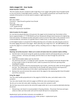
1.2 SPECIFICATIONS
Figure 1-1 Model O231-I2F
62 1/2"
55 5/8"
30 3/8"
20 5/8"
Air Out
26"
21 5/8"
Water Outlet
Air Out
Air In
Water Inlet
Power Connection
Power Connection

Operators Manual #513717 2 O231-I2F Model Machines
1.2 SPECIFICATIONS
O231-I2F Water Cooled O231-I2F Air Cooled
Dimensions Machine with crate Machine with crate
width 26’’ (66,0 cm) 40-1/4’’ (102,2 cm) 26’’ (66,0 cm) 40-1/4’’ (102,2 cm)
height 62-1/2’’ (158,8 cm) 64-1/2’’ (163,8 cm) 62-1/2’’ (158,8 cm) 64-1/2’’ (163,8 cm)
depth 31-1/2’’ (80,0 cm) 33-1/4’’ (84,5 cm) 31-1/2’’ (80,0 cm) 33-1/4’’ (84,5 cm)
Weight 640 lbs (290,2 kg) 730 lbs (331,1 kg) 640 lbs (290,2 kg) 730 lbs (331,1 kg)
Electrical
1 Phase, 208-240
VAC, 60Hz
3 Phase, 208-240
VAC, 60Hz
1 Phase, 208-240
VAC, 60Hz
3 Phase, 208-240
VAC, 60Hz
circuit ampacity
(per barrel)
26A minimum 19A minimum 27A minimum 20A minimum
overcurrent protection
device (per barrel)
40A maximum 30A maximum 40A maximum 30A maximum
International Options 1 Phase, 220-240 VAC, 50Hz & 3 Phase, 380-415 VAC, 50Hz
Compressor
Freezing Cylinders - Two 14,000 Btu/hr
Storage - 1,300 Btu/hr Compressor (R-134a)
Drive Motor Two - 2 hp
Cooling
Water cooled units require 1/2” N.P.T.
water and drain fittings with 2 inlets
and 2 outlets or 1/2” N.P.T. water and
drain fittings with 1 inlet and 1 outlet.
Maximum water pressure of 130 psi.
Minimum water flow rate of 3 GPM.
Ideal EWT of 50°-70°F
Air cooled units require 3” (7,6 cm) air
space at back and sides.
Hopper Volume Two - 6.5 gallon (24,7 liters)
Freezing Cylinder
Volume
Two - 1 gallon (3,79 liters)

Operators Manual #513717 3 O231-I2F Model Machines
SECTION 2
INSTALLATION INSTRUCTIONS
2.1 SAFETY PRECAUTIONS
Do not attempt to operate the machine until the safety
precautions and operating instructions in this manual are
read completely and are thoroughly understood.
Take notice of all warning labels on the machine. The la-
bels have been put there to help maintain a safe working
environment. The labels have been designed to withstand
washing and cleaning. All labels must remain legible for
the life of the machine. Labels should be checked periodi-
cally to be sure they can be recognized as warning labels.
If danger, warning or caution labels are needed, indicate
the part number, type of label, location of label, and quantity
required along with your address and mail to:
STOELTING
ATTENTION: Customer Service
502 Hwy. 67
Kiel, Wisconsin 53042
2.2 SHIPMENT AND TRANSIT
The machine has been assembled, operated and inspected
atthefactory. Uponarrivalat the nal destination,the
entire machine must be checked for any damage which
may have occurred during transit.
With the method of packaging used, the machine should
arrive in excellent condition. THE CARRIER IS RESPON-
SIBLE FOR ALL DAMAGE IN TRANSIT, WHETHER
VISIBLE OR CONCEALED. Do not pay the freight bill
until the machine has been checked for damage. Have
the carrier note any visible damage on the freight bill. If
concealed damage and/or shortage is found later, advise
the carrier within 10 days and request inspection. The
customer must place claim for damages and/or shortages
in shipment with the carrier. Stoelting, Inc. cannot make
any claims against the carrier.
2.3 MACHINE INSTALLATION
WARNING
Installationmust be completedby a qualied
electrician/refrigeration specialist.
Incorrect installation may cause personal injury,
severe damage to the machine and will void fac-
tory warranty.
Installation of the machine involves moving the machine
close to its permanent location, removing all crating, set-
ting in place, assembling parts, and cleaning.
TOOLS NEEDED
• Level
• Screwdrivers, wrenches, channel locks
• Straight edge
• Thermometer
PRIOR TO INSTALLATION
A. On the startup form, complete the following:
1. Buyer Information
2. Distributor Information
3. Authorized Service Provider Information
4. Verify with Store Operator Checklist
5. FreezerCongurationInformation
B. Prepare a USB ash drive with your service
contact information:
1. Locateacopyoftheservicecontactle(info.
txt)
2. Modifythe info.txtle withinformation from
your service company using the instructions
inthele.
3. Savetheservicecontactletotherootlevel
oftheUSBashdrive(donotputtheleinto
any folder).
INSTALLATION
A. Uncrate the machine and install the casters.
Screw the casters into the threaded holes and
tighten them using a pair of channel locks. Set
the machine in place.
B. Accurate leveling is necessary for correct drainage
of the freezing cylinder and to ensure correct
overrun. Place a level on top of the machine
at each corner to check for level condition. If
adjustment is necessary, level the machine by
turning the bottom part of each caster in or out
then tighten the lock nut.

Operators Manual #513717 4 O231-I2F Model Machines
C. In air cooled machines correct ventilation is
required. The left side of the machine is the air
intake and right and back sides are the discharge.
All sides must have 3” minimum clearance.
CAUTION
Failure to provide adequate ventilation will void
warranty.
In water cooled machines, make sure to use
1/2” supply and discharge lines. Follow all local
and state codes for connecting the supply and
discharge lines. Turn on the water supply and
check all connections for leaks.
D. Open the rear panel and check the belt tension
with a Burroughs Belt Tension Gauge. The tension
should be 50-55 lbs. Adjust as necessary and
check the pulley alignment with a straightedge.
NOTE
Belt life is increased if the new drive belts are tight-
ened after two or three weeks of operation.
E. Connect the power cord to the proper power
supply. Refer to the nameplate on your machine
for proper supply. The unit must be connected to
a properly grounded receptacle. The use of an
extension cord is not recommended. Do not use an
adapter to circumvent the grounding requirement.
WARNING
Do not alter or deform electrical plug in any way.
Alteringtheplugtotintoanoutletofdifferentcon-
gurationmaycausere,riskofelectricalshock,
product damage and will void warranty.
F. On the startup form, complete the following:
1. Technical Equipment Inspection, Check-Out,
Startup and Training Checklist (excluding
IntelliTec2™ checks)
2. Refrigeration Cooling Checks
2.4 INTELLITEC2™ SETUP
Every Stoelting soft serve machine needs to be set on site.
The following procedures provide optimal product con-
sistency while prolonging product life.
NOTE
The machine is designed for correct operation in
ambient temperatures between 50°F and 110°F.
Temperatures out of that range may cause refrigera-
tion problems and product quality issues.
A. Disassemble, clean, lubricate, assemble, and
sanitize the machine following the steps in Section
3. Train store personnel at this time.
B. On the startup form, complete the following:
1. Owner/Operator Manual Review & Equipment
Training
2. Startup Operation/Technical Issues
3. Trainee Information
4. Startup Survey
5. Equipment Startup & Training Check Out &
Acceptance
ADDING MIX
A. Sanitize the machine immediately before use.
B. Fill the hopper with at least 2.5 gallons of mix.
C. Place a container under the spigot and open the
spigottoallowthemixtoushoutabout8ounces
(0.23liters)ofsanitizingsolutionandliquidmix.
Close the spigot.
MOTOR CALIBRATION
A. Press the On/Off Left or On/Off Right button. The
Motor Calibration screen will be displayed.
B. Move the cursor over the Left side and press the
SEL button then move the cursor over the Right
side and press the SEL button.
NOTE
The motor calibration can be done for both sides
simultaneously.
C. After the calibration is complete, press the left
arrow button.
SETTING CONTACT INFORMATION (OPTIONAL)
A. PlugyourUSBashdriveintothecontrolifitis
not already plugged in.
B. From the Current Status screen, press the left
arrow button to access the passcode selection
screen. Press the right arrow, SET, and then the
SEL button.
Figure 2-1

Operators Manual #513717 5 O231-I2F Model Machines
C. After the password is accepted, use the arrows to
move the cursor to the Modify Settings option and
press the SEL button. Then move the cursor to
the User Preferences and press the SEL button.
D. On the User Preferences screen move the cursor
to the Contact Information USB Update and press
the SEL button.
E. The screen will change and show “File Found” for
a quick second while it updates the information.
F. After updating the contact information, the screen
will show the Service Contact Information page.
G. Press the left arrow button to go back to the Current
StatusscreenandremovetheUSBashdrive.
SETTING TIME AND DATE
A. Press the right arrow button.
B. Move the cursor to the Modify Settings option
and press the SEL button. Then move the cursor
to the Time and Date option and press the SEL
button and adjust the settings as required.
1. Press the SEL button to enter the Modify Time
and Date screen.
2. Move the cursor to the setting that needs to
be changed and press the SET button.
3. Use the arrow buttons to change the setting
and press the SET button to save the change.
C. Press the left arrow button until the Current Status
screen is displayed.
SETTING CONSISTENCY
A. Install the carburetor.
B. Fill the hopper with liquid mix.
C. Press the Push to Freeze button and let the
machine cycle 1-2 times.
D. Draw product from the barrel immediately after
thecompressorcyclesoffafterthefthtimeand
test the product for consistency and temperature.
E. Adjust the product consistency by increasing or
decreasing the Consist Offset settings. These
settings are under the Modify Settings - Basic
Settings menu
F. Adjust the settings as follows:
1. If the product is too soft, increase the CutIn
Consist Offset.
2. Iftheproductistoorm,decreasetheCutIn
Consist Offset.
F. After the consistency is set, press the left arrow
button once so that the Modify Operating Settings
screen is displayed.
SETTING SERVE TIME AND OVERRUN DETAILS
A. GototheAdvancedSettings(2of2)screenand
scroll down to the Time to Dispense 16 oz option.
B. Time how long it takes to dispense 16 oz of product
into a cup and change the value in the control.
Figure 2-2
Figure 2-4
Figure 2-3

Operators Manual #513717 6 O231-I2F Model Machines
5. Use a straightedge to level the product to the
top edge of the container. Make sure to swipe
across and to not compress the product into
the container.
6. Weigh the frozen product and record the
weight. Empty the container of all frozen
product.
7. Repeat the steps above on the frozen product
three or more times to ensure accurate results.
8. Determine the overrun using the following
equation:
D. Change the value in the control.
E. Press the left arrow button until the Current Status
screen is displayed.
SETTING DISCHARGE PRESSURE ON WATER
COOLED MACHINES
A. Water cooled machines require the water
condenser valves to be adjusted to maintain a
225-235 psig discharge pressure.
When adjusting the discharge pressure the
machine must be under a full load with both
cylinders and the hopper running.
C. Measure to overrun of the product and change
the value in the control.
The following equipment is needed:
• 16 oz container
• Generalpurposescale(Donotuseanoverrun
scale.Theyaredesignedtoworkwithaspecic
volume only.)
• Straightedge
• Liquid mix
• Frozen product
Follow the steps below to properly measure
overrun:
1. Place the container on the scale and zero the
scale.
2. Fill the container to the top edge with liquid
mix. Weigh and record the weight. Empty the
container.
3. Fill the container with frozen product. Make
sure there are no air pockets. Do not close
the spigot until product is over the top edge
of the container.
4. Tap the container on a hard surface to eliminate
air pockets.

Operators Manual #513717 7 O231-I2F Model Machines
SECTION 3
INITIAL SET-UP AND OPERATION
3.1 OPERATOR’S SAFETY PRECAUTIONS
SAFE OPERATION IS NO ACCIDENT; observe these
rules:
A. Know the machine. Read and understand the
Operating Instructions.
B. Notice all warning labels on the machine.
C. Wearproperclothing.Avoidloosettinggarments,
and remove watches, rings or jewelry that could
cause a serious accident.
D. Maintain a clean work area. Avoid accidents by
cleaning up the area and keeping it clean.
E. Stay alert at all times. Know which switch, push
button or control you are about to use and what
effect it is going to have.
F. Disconnect power for maintenance. Never
attempt to repair or perform maintenance on the
machine until the main electrical power has been
disconnected.
G. Do not operate under unsafe operating conditions.
Never operate the machine if unusual or excessive
noise or vibration occurs.
3.2 OPERATING CONTROLS AND INDICATORS
Before operating the machine, it is required that the op-
erator know the function of each operating control. Refer
to Figure 3-1 for the location of the operating controls on
the machine. For the information regarding error codes
displayed on the control panel, refer to the troubleshooting
section of this manual.
A. INTELLITEC2 TOUCHPAD
Main Power On/Off
The Main Power button is used to supply power to the
IntelliTec2™ control, the freezing cylinder circuits and
the storage refrigeration system. When the machine is
rstpluggedin,thecontroldefaultstotheOnstatuswith
power to the hopper only. If the Main Power On/Off button
is pressed when the machine is on, the machine turns off
and a status message displays on the screen.
WARNING
High voltage will shock, burn or cause death. The
OFF-ON switch must be placed in the OFF position
prior to disassembling for cleaning or servicing. Do
not operate machine with panels removed.
Figure 3-1 Machine Controls
IntelliTec2 Control
(See Figure 3-2)
Dispense
Rate Adjustor

Operators Manual #513717 8 O231-I2F Model Machines
Help
Pressing the Help button displays help information depen-
dent on the cursor’s location. Pressing the Help button
again exits the help screen.
Selection Button (SEL)
The SEL button is used by technicians to select menu
options.
Set Button (SET)
The SET button is used by technicians to save changes
when modifying control settings.
On/Off Button
Power to the freezing cylinders is controlled with the On/
Off Left and On/Off Right switches.
Push to Freeze Button
Pressing the PUSH TO FREEZE button initiates “Serve
Mode”.
Clean Button
The CLEAN button initiates “Clean Mode”.
Arrow Buttons (⇐, ⇑, ⇒, ⇓)
The arrow buttons are used by technicians to navigate
through the control readings and settings.
B. DISPENSE RATE ADJUSTOR
The dispense rate adjustor is located under the header
panel, to the immediate right of the spigot handles. Turning
the knob counterclockwise decreases the dispense rate.
C. USB ACCESS PORT
The USB access port is located on the right side panel
of the machine. The port is used by technicians to import
rmwareandexportmachinestatistics.
3.3 EMPTYING THE FREEZING CYLINDER
If the machine is empty, go to Section 3.4.
A. Make sure the Main Freezer Power is on. If the
IntelliTec2™ displays the Current Status Screen,
then the main power is on.
B. Turn off the freezing cylinders by pressing the
On/Off buttons.
C. Remove the hopper covers and remove the
carburetors from the hoppers.
D. Press the Clean buttons. After about 5 minutes
open the spigots to drain the mix.
E. Press the Clean buttons to stop the auger.
F. Filleachhopperwith2gallons(8liters)ofcooltap
water. Optional: Use detergent solution instead of
tap water to make cleaning the parts easier after
disassembly.
G. Press the Clean buttons and let the augers rotate
for at least 30 seconds.
H. While the augers are rotating, scrub the hoppers
with a clean brush.
I. Drain the water out of the machine.
J. Press the Clean buttons to stop the augers.
NOTE
If the water does not drain clear, repeat steps F
through J.
3.4 DISASSEMBLY OF MACHINE PARTS
Before using the machine for the rst time, complete
machine disassembly, cleaning, and sanitizing proce-
dures need to be followed. Routine cleaning intervals and
procedures must comply with the local and state health
regulations. Inspection for worn or broken parts should
be made at every disassembly of the machine. All worn
or broken parts should be replaced to ensure safety to
both the operator and the customer and to maintain good
machine performance and a quality product. Check the
wearlineontheaugerightsonaregularbasis(Fig.3-3)
and replace as needed.
Figure 3-2 IntelliTec2 Control
Wear Line
Figure 3-3 Auger Flight Wear

Operators Manual #513717 9 O231-I2F Model Machines
To disassemble the machine, refer to the following steps:
NOTE
The hopper covers have compartments for all
freezing cylinder parts. The covers help with parts
identication and prevent loss of parts. After dis-
assembly, place the freezing cylinder parts in the
hopper covers to transport them to and from the
washing station.
A. DISASSEMBLY OF FRONT DOOR
1. Press and hold the Main Freezer Power button
for three seconds to turn the power off.
2. Remove the rosette caps or spigot extensions if
installed.
3. Remove the knobs on the front door.
4. Remove the front door by pulling it off the studs.
5. Remove the spigot through the bottom of the front
door.
6. Removeallo-ringsfrompartsbyrstwipingoff
the lubricant using a clean towel. Then squeeze
theo-ringupwardtoformaloop(Fig.3-4).Roll
the o-ring out of the groove.
B. DISASSEMBLY OF AUGER
1. Remove the front auger supports and bushings.
2. Remove the auger assemblies from the machine.
Pull the augers out of the freezing cylinders slowly.
As the augers are being pulled out, carefully
removeeachoftheplasticightswithsprings.
3. Keep the rear of the augers tipped up once they
are clear of the freezing cylinders to prevent the
rear seal assemblies from dropping.
4. Wipe the lubricant off of the hex ends of the
augers with a paper towel. Remove the rear seal
assemblies(Fig.3-5).
5. Unscrewthespringsfromtheaugerights.
3.5 CLEANING DISASSEMBLED PARTS
Disassembled parts require complete cleaning, sanitizing
and air drying before assembling. Local and state health
codes dictate the procedure required. Some state health
codesrequireafoursinkprocess(pre-wash,wash,rinse,
sanitize, air dry), while others require a three sink process
(without the pre-wash step). The following procedures
are a general guideline only. Consult your local and state
health codes for the procedures required in your location.
A. Disassembleallparts.(RefertoSection3.4for
the disassembly of machine parts)
B. Place all parts in 90° to 110°F (32°C to 43°C)
mild detergent water and wash thoroughly. Use
the brushes that shipped with the machine to
cleanallholesinthefrontdoor,ights,mixpickup
assembly, etc.
C. Rinseallpartswithclean90°to110°F(32°Cto
43°C) water.
D. Place all parts in a sanitizing solution for at least
1 minute, then remove and let air dry completely
before assembling in machine.
3.6 CLEANING THE MACHINE
INTERIOR CLEANING
A. Using detergent solution and the large barrel
brush provided, clean the hoppers and freezing
cylinders.
NOTE
Make sure to thoroughly clean the rear seal sur-
faces on the inside of the freezing cylinders.
B. Wrap the brush in a clean cloth and thoroughly
dry the hoppers and freezing cylinders.
C. Remove the drip tray and drain trays. Clean and
replace the trays.
Figure 3-4 Removing O-Ring
Figure 3-5 Rear Seal Assembly

Operators Manual #513717 10 O231-I2F Model Machines
EXTERIOR CLEANING
The exterior should be kept clean at all times to preserve
the luster of the stainless steel. A high grade of stainless
steel has been used on the machine to ease cleanup. To
remove spilled or dried mix, wash the exterior with 90° to
110°F(32°Cto43°C)milddetergentwaterandwipedry.
Do not use highly abrasive materials, as they will mar the
nish.Useasoftclothorspongetoapplythesolution.
For best results, wipe with the grain of the steel.
3.7 ASSEMBLING MACHINE
To assemble the machine parts, refer to the following steps:
NOTICE
Total Blend sanitary lubricant, Petrol-Gel sanitary
lubricant, or equivalent must be used when lubrica-
tion of machine parts is specied.
Total Blend can be used in place of two products. It
is used to lubricate parts and also used in place of
spline lubricant. Do not use more than one packet
of Total Blend per freezing cylinder.
NOTICE
The United States Department of Agriculture and
the Food and Drug Administration require that lubri-
cants used on food processing equipment be certi-
ed for this use. Use lubricants only in accordance
with the manufacturer’s instructions.
A. ASSEMBLE THE REAR SEAL
1. Install the rear seal o-rings onto the augers.
Lubricate the outside of the o-rings with a generous
amount Total Blend lubricant.
2. Lubricate the inside metal surface of the rear
seals(Fig.3-6)andinstallthemontotheauger
shafts. DO NOT lubricate the outside of the rear
auger seals.
3. Lubricate the hex drive ends of the augers with
a small amount of Total Blend lubricant.
B. ASSEMBLE THE AUGER
1. Screw the springs onto the studs in the plastic
ights. The springs must be screwed into the
ightscompletelytoprovidepropercompression.
2. Installthetwoplasticightsontotherearofthe
auger and insert it part way into the freezing
cylinder.
3. Installtheremainingplasticights,pushtheauger
into the freezing cylinder, and rotate slowly until
the auger engages the drive shaft.
4. Apply a thin layer of sanitary lubricant to the inside
and outside of the auger support bushings. Install
the bushings onto the auger supports and install
the auger supports into the front of the augers.
Rotate the auger supports so that one leg of the
support points straight up.
C. ASSEMBLE THE FRONT DOOR
1. Install the o-rings onto the spigot bodies and apply
a thin layer of sanitary lubricant to the o-rings.
Install the spigot bodies through the bottom of
the front door.
2. Fit the front door o-ring into the groove on the
rear of the front door.
3. Place the front door assembly on the mounting
studs and the push front door against the machine
carefully.
NOTE
Make sure the pins of the front door do not touch
the legs of the auger support.
4. Secure the front door to the machine by placing
theknobsonthestudsandtighteninguntilnger
tight. Tighten in a crisscross pattern. Do not
overtighten. Proper o-ring seal can be observed
through the transparent front door.
5. Optional: Install the rosette caps or spigot
extensions.
3.8 SANITIZING
Sanitizing must be done after the machine is clean and
justbeforethemachineislledwithmix.Sanitizingthe
night before does not ensure sanitization the next day.
However, you should always clean the machine and parts
after using it.
NOTE
The United States Department of Agriculture and
the Food and Drug Administration require that all
cleaning and sanitizing solutions used with food
processing equipment be certied for this use.
Figure 3-6 Lubricate Rear Seal

Operators Manual #513717 11 O231-I2F Model Machines
When sanitizing the machine, refer to local sanitary regu-
lations for applicable codes and recommended sanitizing
products and procedures. The frequency of sanitizing
must comply with local health regulations. Mix sanitizer in
quantitiesofnolessthan2gallonsof90°Fto110°F(32°C
to 43°C) water. Allow sanitizer to contact the surfaces to
be sanitized for 5 minutes. Any sanitizer must be used
only in accordance with the manufacturer’s instructions
and provide a 100 parts per million strength solution.
A. For each freezing cylinder, Prepare 2 gallons
of Stera-Sheen sanitizing solution following the
manufacturer’s instructions.
B. Install the carburetors into the hoppers.
NOTE
Do not twist the carburetor when installing.
Withthestandardstyle(Fig3-7),insertitwiththe
air tube towards the front of the machine.
Withtheadjustablestyle(Fig3-8),insertitwith
the angled tube towards the right.
C. Pour the sanitizing solution into the hopper.
D. Make sure the display shows the freezing cylinder
is off. If it is not, press the On/Off button to turn
it off.
NOTE
If the freezing cylinder is not off, the control will
not go into Clean mode. This is to protect from
accidentally going into Clean mode with product
in the cylinder.
E. Press the CLEAN button.
F. Check for leaks.
1. Check for leaks at the front door seal.
2. Check the drain trays located under the front
door for leaks coming from the rear of the rear
auger seals.
G. Use a sanitized soft bristle brush dipped in
sanitizing solution to clean the hopper sides, the
carburetor, and the underside of the hopper cover.
H. Aftertheveminutetimerexpires,openthespigot
to drain the sanitizing solution.
I. Press the CLEAN button to stop the auger. Allow
the freezing cylinder to drain completely.
The machine is now sanitized and ready for adding mix.
3.9 FREEZE DOWN AND OPERATION
A. Sanitize immediately before use.
B. Fill the hopper with at least 2.5 gallons of mix.
C. Place a container under the spigot and open the
spigottoallowthemixtoushoutabout8ounces
(0.23liters)ofsanitizingsolutionandliquidmix.
D. Press the On/Off button to turn on the freezing
cylinder.
E. Allowthefreezingcylindertoll.Thenpressthe
PUSH TO FREEZE button.
F. When the product is ready, the display reads
“SERVE”. Open the spigot to dispense product.
NOTE TO SETUP TECHNICIAN
If the product consistency needs to be adjusted,
use the Technician passcode and go to the Basic
Settings menu. Adjust the CutIn Consistency Off-
set higher to increase the consistency or lower to
decrease the consistency. Make adjustments in
increments of 5 for best results.
G. The machine dispenses product at a reasonable
draw rate. If the machine is overdrawn, the result
is a soft product or a product that will not dispense
at all. If this occurs, allow the machine to run for
approximately 30 seconds before dispensing more
product. A dispense rate adjustor is located under
the header panel, to the immediate right of the
spigot handle. Turning the knob counterclockwise
decreases the dispense rate.
Figure 3-8 Standard Carburetor
Bend towards
right of machine
Air tube towards
front of machine
Figure 3-7 Adjustable Carburetor

Operators Manual #513717 12 O231-I2F Model Machines
H. Do not operate the machine when the MIX
LOW message is displayed. Rell the hopper
immediately.
NOTE
After a preset number of freezing cycles in Serve
mode, the control enters sleep mode and remains
there until someone draws product or presses the
PUSH TO FREEZE button. In the sleep mode, the
machine keeps the product below 41°F (5°C). Sleep
modes do not take the place of cleaning and sanitiz-
ing. Federal, State, and local regulatory agencies
determine frequency of cleaning and sanitizing.
3.10 MIX INFORMATION
Mix can vary considerably from one manufacturer to
another. Differences in the amount of butterfat content
and quantity and quality of other ingredients have a
directbearingonthenishedfrozenproduct.Achange
in machine performance that cannot be explained by a
technical problem may be related to the mix.
Proper product serving temperature varies from one
manufacturer’s mix to another. Mixes should provide a
satisfactory product in the 18°F to 20°F range. Diet and
low-carb mixes typically freeze to proper consistency at
higher temperatures.
When checking the temperature, stir the thermometer in
the frozen product to get an accurate reading.
Old mix, or mix that has been stored at too high a tempera-
ture,canresultinanishedproductthatisunsatisfactory.
To retard bacteria growth in dairy based mixes, the best
storagetemperaturerangeisbetween33°to38°F(0.5°
to 3.3° C).

Operators Manual #513717 13 O231-I2F Model Machines
4.10 CONDENSER CLEANING
The O231 has two condensers. An air-cooled or water-
cooled condenser and a condensing unit for the hopper.
The air-cooled condenser (and hopper condenser) is
a copper tube and aluminum n type. Condensing is
totallydependentuponairow.Apluggedcondenser,or
restrictionsinthelouveredpanelwillrestrictairow.This
will lower the capacity of the system and damage the
compressor. The condenser must be kept clean of dirt
and grease. The machine must have a minimum of 3”
(7.6cm)ofventilationatthesidesandbackoftheunit
forfreeowofair.Makesurethemachineisnotpulling
over100°F(37°C)airfromotherequipmentinthearea.
The water-cooled condenser is a tube and shell type. The
condenser needs a cool, clean supply of water to properly
cool the machine, inlet and discharge lines must be 3/8”
I.D. minimum.
The air-cooled condenser and hopper condenser re-
quire periodic cleaning. To clean, refer to the following
procedures.
A. Visually inspect the condenser for dirt.
B. If the condenser is dirty, place a wet towel over
the condenser.
C. Using compressed air or CO
2
tank, blow out the
dirt from the back of the condenser. Most of the
dirt will cling to the wet towel.
D. An alternative method is to clean with a
condenser brush and vacuum.
NOTE
If the condenser is not kept clean, refrigeration ef-
ciency will be lost.
4.11 PREVENTATIVE MAINTENANCE
It is recommended that a preventative maintenance
schedule be followed to keep the machine clean and
operating properly. The following steps are suggested as
a preventative maintenance guide.
The United States department of agriculture and the food
and drug administration require that lubricants used in
foodzonesbecertiedforthisuse.Uselubricantsonly
in accordance with the manufacturer’s instructions.
A. Daily checks
Check for any unusual noise or condition and
repair immediately.
SECTION 4
MAINTENANCE AND ADJUSTMENTS
4.9 DRIVE BELT TENSION ADJUSTMENT
To check belt tension, refer to Figure 4-4 and follow the
steps below:
A. Remove the back panel.
B. Use a Burroughs Belt Tension Gauge to set the
tension for the drive belt. Set the belt tension to
50-55 lbs.
C. If an adjustment is necessary, loosen the four nuts
on the motor mounting plate and slide the plate
up or down to adjust belt tension. Then retighten
the nuts.
D. Using a straightedge, check that the drive motor
pulley is aligned with the speed reducer pulley.
Align the pulley if necessary.
NOTE
Belt life will be increased if new drive belts are
tightened after two or three weeks of operation.
Figure 4-1 Belt Tension Adjustment
WARNING
Hazardous voltage
Make sure the machine is off when disassembling
for servicing. The machine must be disconnected
from electrical supply before removing any access
panel. Failure to disconnect power before servicing
could result in death or serious injury.
Loosen four nuts to
adjust belt tension
Loosen four nuts to
adjust belt tension

Operators Manual #513717 14 O231-I2F Model Machines
B. Monthly checks
Check the condenser for dirt and clean if
necessary.
C. Quarterly Checks
Check drive belts for wear and tighten belts if
necessary.
4.12 EXTENDED STORAGE
Refer to the following steps for storage of the machine
over any long period of shutdown time:
A. Clean all the parts that come in contact with mix
thoroughly with a warm detergent water. Rinse
in clear water and dry all parts. Do not sanitize.
NOTE
Do not let cleaning solution stand in the freezing
cylinder or hopper during the shutdown period.
B. Remove, disassemble, and clean the front door,
and auger shaft. Leave disassembled during the
shutdown period.
C. Placetheaugerightsandaugersupportbushing
in a plastic bag with a moist paper towel. This will
prevent them from becoming brittle if exposed to
dryairoveranextendedperiodoftime(over30
days).
D. For water-cooled machines that are left in unheated
buildings, or buildings subject to freezing, the water
must be shut off and disconnected. Disconnect
thewaterinlettting.Thettingislocatedatthe
rear of the machine. Run the compressor for 2 - 3
minutestoopenwatervalve(thefrontdoormust
be attached for the compressor to run). Blow
out all water through water inlet. Drain the water
supply line coming to the machine. Disconnect
thewateroutlettting.
E. Press the Main Power On/Off button to turn the
machine off.
F. Disconnect the machine from the source of
electrical supply.
/