Page is loading ...

1
IMPORTANT:
Go to www.extron.com for the complete
user guide, installation instructions, and
specifications before connecting the
product to the power source.
SW4 12G HD-SDI • Setup Guide
The Extron SW4 12G HD‑SDI is a four‑input, two‑output multi‑rate 12G‑SDI switcher that is capable of supporting multi‑rate
SDI. It switches SMPTE SDI video, embedded audio, and ancillary data among four source devices and delivers duplicate output
signals to a pair of SDI displays or peripheral devices. The SW4 12G HD‑SDI supports video resolutions up to 4K @ 60 Hz and
data rates up to 11.88 Gbps, including 3G‑SDI, HD‑SDI, and SDI. It features automatic input cable equalization and output
reclocking to ensure signal integrity over long cable runs. The SW4 12G HD‑SDI has front panel, RS‑232, USB, and auto‑input
switching control options.
NOTE: For full installation, configuration, menus, connector wiring, and operation details, see the SW4 12G HD-SDI User
Guide at www.extron.com.
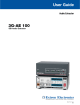
Rear Panel Features
50-60Hz
100-240V 0.1A MAX
1234 AB
INPUTS REMOTEOUTPUTS
SW4 12G HD-SDI
Tx Rx G
RS-232
A
B
C
D
A
AC power connector
C
Output connectors
B
Input connectors
D
RS‑232 control connector
Figure 1. Rear Panel
Installation
1. Turn off all of the equipment and disconnect it from the power source.
2. (Optional) Mount the switcher on top of a at surface using the provided rubber feet, under a table using an optional
under‑desk mounting kit, or to a rack shelf using an optional rack shelf‑mounting kit (kits are available at www.extron.com).
3. Connect up to four SDI, HD‑SDI, or 3G‑SDI video inputs to BNC input connectors 1 through 4 (see gure 1,
B
).
NOTE: Each input is equalized regardless of the rate.
4. Connect one or two video SDI, HD‑SDI, or 3G‑SDI output devices to the rear panel female BNC buffered output connectors
(
C
).
NOTE: Mirrored outputs 1 and 2 output identical signals.
5. If the switcher will be connected to a computer or host controller for remote
conguration and control, do either of the following:
• Wire the provided 3‑pole captive screw connector to an RS‑232 cable.
Connect the RS‑232 cable to the RS‑232 port on the rear panel of
the switcher and to the host RS‑232 port (see the illustration at right).
Protocol for the RS‑232 port is 9600 baud, 8 data bits, 1 stop bit, no
parity.
• Connect a USB A to mini B cable from the computer to the front panel
USB Cong port (see figure 2,
B
, on the next page).
6. Power on the input and output devices, then connect power to the switcher
by connecting the provided IEC power cord to the switcher power connector
(see gure 1,
A
) and to an AC outlet.
Switcher
Receive
Transmit
Ground
RS-232
Tx Rx
DB9 connector (female)
pinout to control equipment
Computer
51
96
Pin RS-232 Function
1 —
2 Rx Receive data (+)
3 Tx T
ransmit data (–)
4 —
5 Gnd Signal ground
6 —
7
——
8
——
9 ——
—
—
—
For information on safety guidelines, regulatory compliances, EMI/EMF compatibility, accessibility, and related topics, see the
Extron Safety and Regulatory Compliance Guide on the Extron website.

2
68-3187-50 Rev. A
09 18
© 2018 Extron Electronics — All rights reserved. All trademarks mentioned are the property of their respective owners. www.extron.com
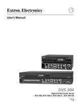
Front Panel Features
SDI SWITCHER
CONFIG
AUTO
SWITCH
SW4 12G HD-SDI
1
INPUTS RATE
2 3 4
270 Mbps 5.94 Gbps
1.485 Gbps 11.88 Gbps
2.97 Gbps OTHER
A
B
C
D
A
AUTO SWITCH LED
C
Input selection buttons and LEDs
B
USB configuration connector
D
Signal Status (RATE) LEDs
Figure 2. Front Panel
Switching an Input to the Outputs
To create a tie between an input and the mirrored outputs:
1. Select the switch mode for the SW4 12G (see “Conguring Auto‑input Switch Mode”). The default is normal.
• Select auto‑input switch mode to select the highest numbered active input or the lowest numbered input.
• Select normal mode to manually select the input to switch to the outputs.
2. Select an input.
• If you are using normal mode, select the desired input by pressing and releasing its input button. The LED beside the
selected input button lights.
• To switch to another input, press the desired input button.
• If you are using auto‑input switch mode, no action is necessary. The switcher automatically switches to the highest or
lowest numbered active input (see “Conguring Auto‑input Switch Mode” to select switching priority).
3. If needed, create a remote connection via USB or RS‑232 (see step 5 of the Installation procedure, on the previous page).
Configuring Auto-input Switch Mode
In auto‑input switch mode, the SW4 12G automatically switches to the highest or lowest numbered active input, depending on
your conguration. When auto‑input switch mode is enabled, the AUTO SWITCH LED (see gure 2,
A
) lights. Auto‑input switch
mode is congured via Extron Simple Instruction Set (SIS) commands as follows:
1. Connect the SW4 12G HD‑SDI to your computer via the rear panel RS‑232 or
front panel USB connector.
2. To enter SIS commands, install and open a terminal emulation utility such as
Extron DataViewer.
3. By default, auto‑input switching is disabled. To enable it and set the input
selection priority, enter one of the following commands:
E = Escape key } = carriage return
• To automatically switch to the highest numbered active input, enter
E1AUSW}.
• To automatically switch to the lowest numbered active input, enter
E2AUSW}.
To turn off auto‑input switching, enter E0AUSW}.
To view the current auto‑input switch mode, enter EAUSW}.
For more information and a complete listing of SIS commands, see the
SW4 12G HD-SDI User Guide, available at www.extron.com.
Application Diagram
The illustration at right shows an example of how the SW4 12G HD‑SDI switcher
can be connected.
50-60Hz
100-240V 0.1A MAX
1234 AB
INPUTS REMOTEOUTPUTS
SW4 12G HD-SDI
Tx Rx G
RS-232
TCP/IP
1
3
1
4
2
31
42
3
1
42
2
3
100
LI
NK
ACT
COM
I
R
I
N
PUT
RELAY
TX
RX
R
I
P
L
2
5
0
®
ON
OFF
DIS
PLAY
MUT
E
SC
REEN
UP
SCREEN
DOW
N
VCR
D
VD
DOC
C
AM
LAPTOP
P
C
MODEL 80
FLAT PANEL
Extron
SW4 12G HD-SDI
Four Input 12G-SDI Switcher
RS-232
12G-SDI Display
12G-SDI
Projector
12G-SDI
Cameras
HD-SDI
Player
TouchLink
Control
System
JOG
SETMENU
12
2160p30
00 : 00 : 00 : 00
1:45:24
/