3M SFT-150 Installation guide

Type
Installation guide

This manual is also suitable for

3M SFT Softener
Installation and Operating Manual for model:
SFT - 150/200
Please read this user manual carefully
and keep this manual properly
.
INSTALLATION PRECAUTION
Incoming Water Temperature 4.4-37.8
o
C (40-100
o
F)
Incoming Water Pressure 172-862 kPa (25-125 psi)
Voltage / Frequency 220V / 50Hz
Before installation of this product, please ensure that all conditions meet local water and electricity
requirements and relevant laws and regulations. If you have any question, feel free to contact your local
sales representative or the 3M Company.
1. The packaging materials could pose as a danger to children. Keep the packaging materials (such as
plastic bag) out of reach of children;
2. To reduce the risk of choking, do not allow children to have access to small parts during the
installation of this product.
3. Do not use with water that is microbiologically unsafe or of unknown quality without adequate
disinfection before or after the system.
4. Install system on COLD water lines only. The temperature of the incoming water should be between
4.4-37.8oC (40-100oF).
5. Do not install if water pressure exceeds 172-862 kPa (25-125 psi). If water pressure exceeds 862 kPa
(125 psi), you must install a pressure limiting valve.
6. Use the original power adapter provided with the system and connect it to home socket. The rated
voltage of which should be 220V/50Hz. The power socket should be grounded and equipped with
overload protection units (such as breaker or safety fuse).
7. Do not install system near high temperature area or equipment.
8. Recommended to install system indoor or under shelter.
9. Protect from freezing. Drain system when room temperature drops below 40°F (4.4°C)
10. Do not install system where water lines could be subjected to vacuum conditions without
appropriate measures for vacuum prevention.
11. Take care when using pliers or pipe wrenches to tighten plastic ttings, as overtightening may cause
damages.
12. To ensure that the installation conforms to your country/state plumbing requirements, it is
recommended that the installation be performed by a licensed plumber.
13. SHUT OFF FUEL SUPPLY TO WATER HEATER after water supply is shut o.
14. Failure to install the system as instructed will VOID the warranty.
Operating Parameters
3M SFT Softener
Table of content
One General introduction
Two Requirements for installation and notice
1 Product specifications...............................................................02
2 Product structure......................................................................03
3 Product function........................................................................05
Requirements for installation and notice......................................06
Three Main steps for installation
1 Preparation before installation
2 Installation of bypass-valve.......................................................07
3 Connection of inlet and outlet pipe...........................................08
4 Installation of drain pipe and overflow pipe..............................09
5 Power connection....................................................................09
..................................................07
Four Setting and operation of the controller
1 General introduction of the controlling interface........................11
2 Parameters setting in installation and debugging......................11
3 Checking and setting of operation parameters..........................12
4 Manual operation of cleaning and regeneration........................13
5 The introduction of cleaning and regeneration process ...........14
6 Checking of historical data........................................................15
Five Water flow test of the Softener
1 Primary inflow of the Softener..............................................17
2 Working conditions of bypass-valve.....................................17
3 Debugging of salt washing and water injection....................18
4 Debugging the softener and other notes..............................18
Six Maintenance and trouble-shooting of the Softener
1 Daily operation and maintenance of the Softener
2 Troubleshooting of the Softener...........................................20
3 List of components on the controller.....................................21
................19
Seven How to protect your rights and interests?
1 Quality and warranty.............................................................25
One General introduction
1.1 Product Specifications
Flow Rate per Hour
Above index may change without specific notice.
4.4-37.8
o
C (40-100
o
F)
172-862 kPa (25-125 psi)
220V / 50Hz
Φ13mm, Φ16mm
¾”
1.5 ton 2 ton
SFT-150 SFT-200
Incoming Water Temperature
Incoming Water Pressure
Voltage / Frequency
Water Inlet / Outlet Connection
Drainage Connection
1.2 Product Structure
SFT-150
SFT-200
470
483.5
460
482.5
661
1123
≤21
≤35
502
964
1
2
3
4
5
6
7
8
9
10
11
12
13
14
15
Bypass Control Valve
Inlet and Outlet Control Valve
3/8” Polyethylene Tubing
Overflow Port Connector
Brine Valve Assembly
Brine Tank Assembly (incl Cover)
Body
Resin Tank assembly (including a center tube set parts,
ion exchange resin)
Bracket
Brine Tank Cover
Control Valve Assembly (including limiting valves, electrical
power adapter)
Drain Connection
Cover
Power adaptor
Plastic packing components
1
2
1.3 meters
1
1
1
1
1
1
1
1
1
1
1
1
Product Dimension (mm)
Width
A (mm)
Product Weight (excluding salt) (kg)
Depth Height
Item description
Quantity
Series
number
For models SFT-150 and SFT-200
1.3 Product function
Product features:
Softening:
The SFT series softener bears many characteristics, for instance high water yield, good
water softening effect, stable operation, etc.The SFT series softener is equipped with intelligent
operations such as automatic cleaning and automatic regeneration.This product bring to you and
your family a cleaner and smoother water experience with its high water quality for your everyday
life - the ideal choice for great bathing experience, daily washing and protection for hot water appliances.
.
- Built-in 24 hours time control system. Automatic cleaning can be achieved as per the setting of
regeneration interval and time (factory preset time is 2am);
- Intelligent control system can set the most economical and effective water softening program,
automatic cleaning and regeneration program according your water condition and consumption.
- Standard cleaning and regeneration process are as follows:
After source water flow through the softener under certain pressure and flow rate, sodium ions in the
ion-exchange resin will go on an exchange with the cations (calcium ion and magnesium ion) in the
water thus reducing the consistency of those ions in water and softening.
Backwashing:
The saturated ion exchange resin needs to be backwash before regenerating. One of the reasons
for doing that is to wash off broken resin and suspended impurity that have remained on the surface of
resin. The other reason is to loosen the firm resin bed so that the resin will have a better contact with the
brine solution, providing a more favorable regeneration condition for the ion-exchange resin.
Brine washing and regeneration:
Brine solution of certain concentration and flow rate flows through the ion-exchange resin,
regenerating the saturated resin so as to restore the original softening exchange capability.
Flushing:
Flash out any residual brine solution in the resin, until the standard qualified water is achieved;
compressing the resin so as to optimize the softening effect.
Brine tank replenishment:
Replenishing brine solution for future usage during regeneration.
2 Requirements for installation and notice
*The location to install this equipment must have AC power, water inlet and water outlet connection,
floor drain and sewage discharge outlet.
* All water pipe and electric connections used are recommended to meet relevant national standard;.
*Keep this equipment away from acidic substance or gas to avoid corrosion.
*Please use AC 220V / 50Hz single-phase electric power rather than any other power supply. The
power socket should be grounded and equipped with overload protection units (such as breaker or
safety fuse).
*The equipment should be installed vertically, not upside-down or horizontally. And it should be kept in
an upright position in transit. Do not allow it to be tilted while handling to avoid damages to
equipment.
*The recommended water incoming pressure is 172-862 kPa (25-125 psi). Booster bump or
pressure-relief valve is to be installed either below or above this standard.
*Make sure that the sewer drainage remains clear and that there is a distance between the drainage
pipe and sewage water to prevent back flow of sewage water into the eqeuipment. Do not insert
drainage pipe into the sewage water. Size of floor drain pipe should not be less than DN40.
*To avoid leakage in the system or pipeline over time, take cautious on the height and angle when
connecting the pipes to avoid stress.
* Take care when using pliers or pipe wrenches to tighten plastic fittings, as overtightening may cause
damages to the threading.
* Before connecting the inlet water pipe, clear any residual impurities and dirt in the pipeline first. Turn
off the main valve then connect the pipes to the equipment.
* Recommended to install system indoor or under shelter.For outdoor installation, it is recommended
to build awning and take protective measures for the body andthe pipeline. Prevent it from direct
sunlight, rain, wind, heat and cold, pollution, theft or animal damage.
* The temperature of the incoming water should be between 4.4-37.8oC (40-100oF). If the water
heater is installed after the softener, one-way check valve should be installed at the pipeline to
prevent backflow of hot water.
*Make sure that the softener is installed and maintained by 3M or 3M authorized dealer and installers.
3 Main steps for installation
3.1 Preparation before Installation
3.1.1 Checked that all installation conditions are met before installation. Confirm that the inlet and outlet
pipes, power and floor drain of sewage discharge outlet are conform to the requirements.
3.1.2 First, turn off the main water supply. Then turn on the water faucet to drain off any
excess water from the pipe.
Width * Depth (mm)
500 x 700
SFT -150/200
Note: The above measurement is for recommendation only. The actual size for installation to be
determined based on site conditions.
3.1.4 Take the product out of the packing box and remove
all packing. Check the product for any damages that may
occur during transportation. Make sure that the equipment
is without any damage during the transport.
3.2 Installation of by-pass valve :
Locate the by-pass valve and in the accessory pack. Insert the 1” quick
connect nut, split ring and O-ring in the respective order shown in Fig3.2a.
3.1.5 To install and configure the softener, remove the upper lid
(Fig.3.1.4)
Fig. 3.1.4
.
Fig.3.2a Water Inlet Connector
O-ring
Split Ring
Fitting 1"
Plastic Male
NPT
1” Quick Connect Nut
The O-ring should be fitted into the 1” quick connect nut . And the 1” male NPT fitting connects to the
by-pass valve through the 1” quick connect nut. The by-pass valve assembly will then be connected to
the control valve body via the union connection (Fig 3.2a).
By-pass valve, Inlet and Outlet connector
Note: Do not use any tool to tighten the union connections.
Tightening by hand is sufficient.
3.1.3
Fig.3.3.2 Flow Direction Sign
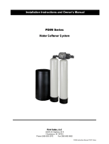
Fig.3.3.3 Connection of Inlet and Outlet Pipeline
Soft Water Outlet
Hard Water
Inlet
3/4” Female
Connection
By-Pass Valve
3.3 Inlet / Outlet Pipe Connection
Notice:
Note: The operation guide is for reference only. Please contact the tube and
pipe seller should there are questions.
Alert: If the household electric system needs the use of cooler system as
electrical safety grounding to earth, jumper is suggested to ensure that the entire
softenerpipe to ground.
3.3.1 Confirm that the inlet water valve is turn off and confirm the
water outlet location.
3.3.2 Connect the inlet pipe and outlet pipe to the by-pass valve
according to the arrows marked on the bypass valve for water flow
direction (Fig3.3.2). Inlet & outlet connection of the bypass valve is
a ¾” BSP male thread.
3.3.3 Connection of pipe and water softener should be done after
completion of all the welding of PPR or brass pipe (not included with
system) to avoid damage to the softener components by any heat
generated by welding.
PPR Pipe Installation
Step1: Pipe-cutting. Cut pipe with a pipe cutter.
Attention: Cut the pipe as flat as possible, or it will influence the
welding result.
Step2: Marking. Make marking on the pipe before welding.
Step3: Heating. Insert tube and fitting into the die at the same time.
Attention: The typical heating period time is 8-9 seconds. Insufficient
or overheating will cause under heating or pipe to collapse.
Step4: Welding. Remove the tubes and fittings out of the welder,
and insert in place quickly and smoothly without any rotation.
Attention: Should the connection time be too long, connection will
not be strong or not in place.
Step5: Cooling. It is important to cool the pipe after welding.
Attention: Cooling time is generally 4-5 seconds. Avoid twisting, bent
and pulled before sufficient cooling.
* Avoid knocking the pipes or tubing during storage, transportation
and installation process.
* UV protective measures and insulation measures should be
taken when mounting the pipes.
* Take into consideration that temperature may cause deformation of
the pipe for surface mounted and non-concealed type of pipe installation.
* During pipe installation, the working environment temperature is preferably 5 degrees Celsius
higher. If less than 5 degrees Celsius, the heating time required is extended by 50%.
* Do not over tighten thread connections. Over-tightening may cause damages to the threading.
* Place machine on a flat surface. Inlet and outlet pipes should be secured with pipe holder to
avoid additional pressure or weight exerted on the bypass valve.
* Insulate the pipes and valves should there be a possibility of freezing.
3.4 Installation of drainage pipe and overflow pipe
Note: To ensure smooth operation for the water softener regeneration process,
ensure that there is no blockage of drains.
Note: If the drainage hose is placed too high or is inserted into the sewage, it will cause
pressure drop during water softener regeneration. This will cause incompletion of normal
salt wash regeneration process.
3.4.1 Connect flexible drainage hose (16mm inner diameter) to the drainage control valve. Use hose
clamps to secure hose to prevent hose from coming loose.
3.4.2 Connect the other end of flexible drainage hose to drainage outlet such as floor drain, drainage
pool. Avoid elevating the drainage hose. Long and bending angle is not advisable as “kink” hose may
occur and hose will then need to be replaced.
3.4.3 Secure drainage hose to drainage outlet firmly. During backwash and regeneration process, the
water pressure may loosen the water hose, causing water to sputter out of the drain area. To prevent
backflow of drainage water into the system, there should be clearance of at least 4 cm between the
end of the drainage hose and the sewage drain water. Never insert the drain pipe directly into the
sewage. Do not raised the drain hose to more than 2.5 meters above the ground.
3.4.4 Connect the 13 mm (inner diameter) hose to the barrel or overflow outlet of the salt tank
and secure with hose clamps.
3.4.5 Fix the overflow drainage hose to drainage outlet such as floor drain, drainage pool. The
overflow drainage hose must be below the overflow outlet. Do not connect with the 16mm inner
diameter soft drainage hose in 3.4.1.
Inlet and Outlet
Water Hose
Overflow
Drainage Hose
Drainage
Outlet
Floor Drain
Power Socket
Fig 3.4a SFT-150/200 Installation Guide
1 Display: Display of operating parameters, time parameters and operating status.
2) SET CLOCK: Switch to setting state, setting of time parameters, brine quantity parameters.
Saving of settings and exit setting process.
3) NEXT: Confirm setting. Switch to the next parameter setting.
4) / : Selection (increase or decrease) of setting value
5) REGEN: Regeneration at a scheduled time / Hold button for 5 seconds for immediate
regeneration / Returning to previous screen during the setting process
6) To Lock / Unlock Display Screen: Press the buttons in the following sequence: → NEXT →
→SET CLOCK
4.2) Installation and Commissioning Parameter Setting
4.2.1) A self- test procedure will be performed after the controller is connected to the power supply. It
is normal if sound of motor rotation could be heard.
4.2.2) After the self-test procedure is completed, press NEXT and simultaneously for 3 seconds to
enter the installation and commissioning parameter interface.
3.5 Power Connection
Insert the supplied 220-volt power adapter into the power outlet.
SET
NEXT
Down
Regeneration
and cleaning
Display Screen
SET
CLOCK
SET HARDNESS
NEXT
REGEN
4.1 Controller Panel Overview
Step 1: Setting Local Water Hardness
Set the water hardness in milligrams per
liter of calcium carbonate hardness using
the or . Default value is 340. Value
should range between 1-2500. To proceed
to Step 2, press NEXT. To exit setting
mode, press REGEN.
Note:Any usage of water during
regeneration process will affects
the regeneration effectiveness.
Hence, it is advisable to set
regeneration at time like 2:00am.
Note: Contact local 3M seller if you are unsure of the local water hardness.
Step 2: Days Override
Day override sets the number of days between regenerations and sets the maximum number of days
between regenerations. Default setting is 14 days. Set Day Override using or :
• number of days between regeneration (allowable range from 1 to 28); or “OFF”.
Press NEXT to go to step 3. Press REGEN to exit this setting.
Note: If value is set as a number (allowable range from 1 to 28), a regeneration initiation
will be called for on that day even if sufficient number of gallons were not used to call for
a regeneration.
Step 3: Setting of Regeneration Time:
To set start time – press the / to change the flashing Hour to the desired value. Press NEXT to
select the Minutes value. Once the Minute is flashing, press / to select desired value.
The default time is 2:00 am.
Press NEXT to proceed to Step 4. Press REGEN to exit this setting.
SET
CLOCK
SET
REGEN
DAY
NEXT
REGEN
Note:Any usage of water during regeneration process will affects the regeneration
effectiveness.Hence, it is advisable to set regeneration at time like 2:00am.
.
Softening
Time
Current time interface
Capacity
Left
4.3 Setting of operational parameters
4.3.1 When the system is operating, one of two displays will be shown. Pressing NEXT will alternate
between the displays. One of the displays is always the current time of day. The second display is
one of the following: days remaining or gallons remaining. Days remaining is the number of days left
before the system goes through a regeneration cycle. Capacity remaining is the number of gallons
that will be treated before the system goes through a regeneration cycle. The user can scroll between
the displays as desired.
If the system has called for a regeneration that will occur at the preset time of regeneration, the words
REGEN TODAY will appear on the display. When water is being treated (i.e. water is flowing through
the system) the word “Softening” or “Filtering” flashes on the display if a water meter is installed.
4.3.2 Set Time of Day
The user can also set the time of day. Time should only need to be set after extended power outages or
when daylight saving time begins or ends. If an extended power outage occurs, the time of day will flash
on and off which indicates the time of day should be reset.
Step 1 - Press SET CLOCK.
Step 2 - Current Time (hour): Set the hour of the day using / button. AM/PM toggles after 12. Press
NEXT to go to step 3.
Step 3 - Current Time (minutes): Set the minutes of the day using / buttons. Press NEXT to exit Set
Clock. Press REGEN to return to previous step.
Note: If time of day is set incorrectly, the time set for regeneration process may be affected.
4.4.1 Sometimes there is a need to regenerate the system sooner than when the system calls for it,
usually referred to as manual regeneration. There may be a period of heavy water usage because of
guests or a heavy laundry day.
To initiate a manual regeneration immediately, press and hold the “REGEN” button for five seconds. The
system will begin to regenerate immediately. The request cannot be cancelled.
4.4.2 To initiate a manual regeneration at the present delayed regeneration time, press and release
“REGEN”. The words “REGEN TODAY” will flash on the display to indicate that the system will regenerate
at the preset delayed regeneration time.
4.4 Manual Regeneration
Note: For softeners, if brine tank does not contain salt, fill with salt and wait at least
two hours before regenerating.
Note: If you pressed the "REGEN" button in error, pressing the button again will
cancel the request.
4.5 Introductory to Regeneration Process
4.4.2 To initiate a manual regeneration at the present delayed regeneration time, press and release
“REGEN”. The words “REGEN TODAY” will flash on the display to indicate that the system will regenerate
at the preset delayed regeneration time.
Note: If you pressed the "REGEN" button in error, pressing the button again will cancel the request.
The regeneration process includes backwash, salt wash, rinse, second rinse, and water filling.
The total process takes about 50~110 minutes, depending on the model and parameters set.
When the system begins to regenerate, the display will change to include information about the step of
the regeneration process and the time remaining for that step to be completed. The system runs through
the steps automatically and will reset itself to help provide treated water when the regeneration has been
completed during the regeneration process, user can press REGEN to skip the countdown to proceed to
the next step.
4.5.1 The regeneration process screen will be displayed on the display panel. Backwashing will be
displayed first and the time remaining to complete the backwash.
4.5.2 After completing the backwashing process, the salt washing process will starts automatically and
displaying the time remaining to complete the backwash.
4.5.3 After completing the salt wash process, the system starts the second backwash process and
displaying the time remaining to complete this process.
4.5.4 After completing the second backwash process, the rinsing process will begins and the time
remaining to complete the rinse process will be displayed.
4.6 Diagonstic
Press and simultaneously for three seconds and release.
Note: If screen in 4.6.1 does not appear in 5 seconds, the lock on the
valve is activated. To unlock display screen,
press → NEXT → →SET CLOCK
4.5.5 After completing the rinsing process, the system starts the water filling process and displaying
the time remaining to complete this process
4.5.6 After completing the water filling process, the regeneration process is completed. The system will
return to normal operational mode and display panel will shows current time.
Change Bleach Washing to Rinse
Change water injection to Water Filling
4.6.2
4.6.2 Gallons, since last regeneration: This display shows the number of gallons that have been treated
since the last re generation. This display will equal zero if a water meter is not installed. Press the NEXT
button to go to next parameter. Press REGEN to return to previous step.
4.6.1 Days, since last regeneration: This display shows the days since the last regeneration occurred.
Press the NEXT to go to next parameter. Press REGEN to exit Diagnostics.
4.6.3 Gallons, reserve capacity used for last 7 days: If the valve is set up as a softener, a meter is
installed and Set Gallons Capacity is set to “Auto,” this display shows 0 day (for today) and flashes the
reserve capacity. Pressing the
button will show day 1 (which would be yesterday) and flashes the reserve capacity used. Pressing
the button again will show day 2 (the day before yesterday) and the reserve capacity. Keep pressing
the button to show the gallons for days 3, 4, 5 and 6.
The button can be pressed to move backwards in the day series. Press the NEXT button at any time
to go to next parameter. Press REGEN to return to previous step.
4.6.4 Gallons, 63 day usage history: This display shows day 1 (for yesterday) and flashes the
number of gallons treated yesterday. Pressing the button will show day 2 (which would be the
day before yesterday) and flashes the number of gallons treated on that day. Continue to press
the button to show the maximum number of gallons treated for the last 63 days. This display
will show dashes if a water meter is not installed. Press the NEXT button at any time to go to
next parameter. Press REGEN to return to previous step.
4.6.5 Flow rate, current: Turn the water on at one or more taps in the building. The flow rate in gallons
per minute will be displayed. If flow stops the value will fall to zero in a few seconds. This display will
equal zero if a water meter is not installed. Press the NEXT button at any time to go to next parameter.
Press REGEN to return to previous step.
4.6.6 Flow rate, maximum last seven days: The maximum flow rate in gallons per minute that
occurred in the last seven days will be displayed. This display will equal zero if a water meter is not
installed. Press the NEXT button to go to next parameter. Press REGEN to return to previous step.
4.6.7 Gallons, total used since last reset: The total number of gallons used since last reset will be
displayed. This display will equal zero if a water meter is not installed. Press the NEXT button to go to
next parameter. Press REGEN to return to previous step.
4.6.8 Days, total number since last reset: The total number of days the control valve has been in
service since last reset will be displayed. Press the NEXT button to go to next parameter. Press
REGEN to return to previous step.
4.6.9 Regenerations, total number since last reset: The total number of re generations that have
occurred since last reset will be displayed. Press the NEXT button to exit Diagnostics. Press
REGEN to return to previous step.
When desired, all information in Diagnostics may be reset to zero when the valve is installed in a new
location. To reset to zero, press NEXT and
buttons simultaneously to go to the Service/OEM screen,
and release. Press and simultaneously to reset diagnostic values to zero. Screen will return to
user display.
5. Water Flow Test of the Softener
5.1 Primary inflow of the Softener
5.1.1 Refer to Section 3 of the manual on the installation of the softener. Refer to Section 4 of the
manual to complete the setup of control valve and regeneration settings.
5.1.2 Activate regeneration manually by referring to Section 4.4 - “Manual Regeneration”.
5.1.3 Partially open INLET knob on bypass valve (Fig 3.3.2). This will allow the unit to fill slowly
from the bottom up, reducing air entrapment. Allow unit to fill slowly, failure to do so could result in
loss of resin to the drain.
5.1.4 Once a steady stream of water, no air, is flowing to drain the inlet and outlet knobs on the
bypass can be fully opened.
5.1.5 Slowly turn on the water faucet and main water supply. Once all air has been purged out of
the system and there is a steady flow of water, turn off water faucet and main water supply.
5.1.6 Initial water flow test has completed, open the inlet and outlet knob of bypass valve (Fig.
5.2.1) to check for any leakage or seepages. Repair any leakage or seepages.
5.2.1 Normal operation (Fig. 5.2.1): Untreated water enters the system via the inlet of the
bypass valve. Soft water exit system via the outlet of the bypass valve to users.
5.2.2 Bypass operation (Fig. 5.2.2): Untreated water enters the inlet of bypass valve and exit
the system via the outlet of bypass valve as the system is being bypass and no water is flowing
into the system. At this state, the bypass valve can be dismantle from the softener to conduct
any maintenance work on the softener.
5.2 Position of bypass-valve
Soft water Untreated water
Untreated water Untreated water
Fig 5.2.1
Fig 5.2.2
Untreated water Untreated water
5.2.3 Diagnostic operation (Fig. 5.2.3): Untreated water enters the inlet of bypass valve and diagnostic
operation can be perform when process such as manual regeneration is activated. Untreated water exit the
system via the outlet of bypass valve into the outlet pipe.
5.2.4 Off Mode (Fig. 5.2.4): Completely no water flow to the system or outlet pipe as bypass valve is off.
Fig 5.2.3
Fig 5.2.4
  • Page 1 1
  • Page 2 2
  • Page 3 3
  • Page 4 4
  • Page 5 5
  • Page 6 6
  • Page 7 7
  • Page 8 8
  • Page 9 9
  • Page 10 10
  • Page 11 11
  • Page 12 12
  • Page 13 13
  • Page 14 14
  • Page 15 15
  • Page 16 16
  • Page 17 17
  • Page 18 18
  • Page 19 19
  • Page 20 20
  • Page 21 21
  • Page 22 22
  • Page 23 23
  • Page 24 24
  • Page 25 25
  • Page 26 26
  • Page 27 27
  • Page 28 28
  • Page 29 29
  • Page 30 30
  • Page 31 31
  • Page 32 32
  • Page 33 33
  • Page 34 34

3M SFT-150 Installation guide

Type
Installation guide
This manual is also suitable for

Ask a question and I''ll find the answer in the document

Finding information in a document is now easier with AI