Chicago Electric 96712 Owner's manual
- Category
- Power tools
- Type
- Owner's manual
This manual is also suitable for

!"#"$%&'(%)*+#"$*%,$-%.$$/-00)))1.,(+&(2(*"3.$14&5
65,"7%&'(%$*4.8"4,7%#'//&($%,$-%/(&9'4$#'//&($:.,(+&(2(*"3.$14&5
Owner’s Manual & Safety Instructions
Save This Manual%Keep this manual for the safety warnings and precautions, assembly,
operating, inspection, maintenance and cleaning procedures. Write the product’s serial number in the
back of the manual near the assembly diagram (or month and year of purchase if product has no number).
Keep this manual and the receipt in a safe and dry place for future reference. 17l
When unpacking, make sure that the product is intact
and undamaged. If any parts are missing or broken,
please call 1-888-866-5797 as soon as possible.
Copyright
©
2007 by Harbor Freight Tools
®
. All rights reserved.
No portion of this manual or any artwork contained herein may be reproduced in
any shape or form without the express written consent of Harbor Freight Tools.
Diagrams within this manual may not be drawn proportionally. Due to continuing
improvements, actual product may differ slightly from the product described herein.
Tools required for assembly an d se rv ic e may n ot b e in cl uded.
;*,9%$."#%5,$*(",7%+*2&(*%'#"83%$."#%/(&9'4$1%
<,"7'(*%$&%9&%#&%4,8%(*#'7$%"8%#*("&'#%"8='(>1%
?@!6%ABC?%D@EF@G1

Page 2 <&(%$*4.8"4,7%H'*#$"&8#I%/7*,#*%4,77%JKLLLKLMMKNOPO1 Item 96712
?@<6AQ RS6;@ACRE D@CEA6E@ET6?6AFS
A,+7*%&2%T&8$*8$#
Safety ......................................................... 2
Specifications ............................................. 7
Setup .......................................................... 7
Operation .................................................... 8
Maintenance ................................................
Parts List and Diagram .............................. 11
Warranty .................................................... 12
U@;ECEV%?QDWRG?%@EX%X6<CECACRE?
This is the safety alert symbol. It is used to alert you to potential
personal injury hazards. Obey all safety messages that
follow this symbol to avoid possible injury or death.
Indicates a hazardous situation which, if not avoided,
will result in death or serious injury.
Indicates a hazardous situation which, if not avoided,
could result in death or serious injury.
Indicates a hazardous situation which, if not avoided,
could result in minor or moderate injury.
Addresses practices not related to personal injury.
CDSR;A@EA%?@<6AQ%CE<R;D@ACRE
V*8*(,7%S&)*(%A&&7%?,2*$>%U,(8"83#
;*,9%,77%#,2*$>%),(8"83#%,89%,77%"8#$('4$"&8#1%%
Failure to follow the warnings and instructions may result in electric shock, fire and/or serious injury.
?,Y*%,77%),(8"83#%,89%"8#$('4$"&8#%2&(%2'$'(*%(*2*(*84*1
The term ″power tool″ in the warnings refers to your mains-operated (corded) power tool.
U&(Z%@(*,%?,2*$>
1. [**/%)&(Z%,(*,%47*,8%,89%)*77%7"$1%%
Cluttered or dark areas invite accidents.
2. X&%8&$%&/*(,$*%/&)*(%$&&7#%"8%*\/7&#"Y*%
,$5&#/.*(*#I%#'4.%,#%"8%$.*%/(*#*84*%&2%
27,55,+7*%7"H'"9#I%3,#*#%&(%9'#$1 Power tools
create sparks which may ignite the dust or fumes.
3. [**/%4."79(*8%,89%+>#$,89*(#%
,),>%)."7*%&/*(,$"83%,%/&)*(%$&&71
Distractions can cause you to lose control.

Page 3<&(%$*4.8"4,7%H'*#$"&8#I%/7*,#*%4,77%JKLLLKLMMKNOPO1Item 96712
?@<6AQRS6;@ACRED@CEA6E@ET6 ?6AFS
67*4$("4,7%?,2*$>
1. S&)*(%$&&7%/7'3#%5'#$%5,$4.%$.*%&'$7*$1%%
E*Y*(%5&9"2>%$.*%/7'3%"8%,8>%),>1%%
X&%8&$%'#*%,8>%,9,/$*(%/7'3#%)"$.%3(&'89*9%
/&)*(%$&&7#1 Unmodified plugs and matching
outlets will reduce risk of electric shock.
2. @Y&"9%+&9>%4&8$,4$%)"$.%3(&'89*9%#'(2,4*#%
#'4.%,#%/"/*#I%(,9",$&(#I%(,83*#%,89%
(*2("3*(,$&(#1% There is an increased risk of
electric shock if your body is grounded.
3. X&%8&$%*\/&#*%/&)*(%$&&7#%$&%(,"8%&(%)*$%
4&89"$"&8#1 Water entering a power tool
will increase the risk of electric shock.
4. X&%8&$%,+'#*%$.*%4&(91%%E*Y*(%'#*%$.*%4&(9%
2&(%4,((>"83I%/'77"83%&(%'8/7'33"83%$.*%
/&)*(%$&&71%%[**/%4&(9%,),>%2(&5%.*,$I%&"7I%
#.,(/%*93*#%&(%5&Y"83%/,($#1%%Damaged or
entangled cords increase the risk of electric shock.
5. U.*8%&/*(,$"83%,%/&)*(%$&&7%&'$9&&(#I%
'#*%,8%*\$*8#"&8%4&(9%#'"$,+7*%2&(%
&'$9&&(%'#*1 Use of a cord suitable for outdoor
use reduces the risk of electric shock.
6. C2%&/*(,$"83%,%/&)*(%$&&7%"8%,%9,5/%7&4,$"&8%
"#%'8,Y&"9,+7*I%'#*%,%V(&'89%<,'7$%T"(4'"$%
C8$*(('/$*(%]V<TC^%/(&$*4$*9%#'//7>1
Use of a GFCI reduces the risk of electric shock.
S*(#&8,7%?,2*$>
1. ?$,>%,7*($I%),$4.%).,$%>&'%,(*%9&"83%
,89%'#*%4&55&8%#*8#*%).*8%&/*(,$"83%
,%/&)*(%$&&71%%X&%8&$%'#*%,%/&)*(%
$&&7%)."7*%>&'%,(*%$"(*9%&(%'89*(%$.*%
"827'*84*%&2%9('3#I%,74&.&7%&(%5*9"4,$"&81
A moment of inattention while operating power
tools may result in serious personal injury.
2. F#*%/*(#&8,7%/(&$*4$"Y*%*H'"/5*8$1%%
@7),>#%)*,(%*>*%/(&$*4$"&81 Protective
equipment such as dust mask, non-skid safety
shoes, hard hat, or hearing protection used for
appropriate conditions will reduce personal injuries.
3. S(*Y*8$%'8"8$*8$"&8,7%#$,($"831%
68#'(*%$.*%A("33*(%"#%"8%$.*%&22K/&#"$"&8%+*2&(*%
4&88*4$"83%$&%/&)*(%#&'(4*I%/"4Z"83%'/%&(%
4,((>"83%$.*%$&&71
Carrying power tools with your finger on
the Trigger or energizing power tools that
have the Trigger on invites accidents.
4. X&%8&$%&Y*((*,4.1%%[**/%/(&/*(%2&&$"83%,89%
+,7,84*%,$%,77%$"5*#1 This enables better control
of the power tool in unexpected situations.
5. X(*##%/(&/*(7>1%%X&%8&$%)*,(%7&&#*%47&$."83%&(%
=*)*7(>1%%[**/%>&'(%.,"(I%47&$."83%,89%37&Y*#%
,),>%2(&5%5&Y"83%/,($#1 Loose clothes, jewelry
or long hair can be caught in moving parts.
6. C2%9*Y"4*#%,(*%/(&Y"9*9%2&(%$.*%4&88*4$"&8%&2%
9'#$%*\$(,4$"&8%,89%4&77*4$"&8%2,4"7"$"*#I%*8#'(*%
$.*#*%,(*%4&88*4$*9%,89%/(&/*(7>%'#*91 Use of
dust collection can reduce dust-related hazards.
7. R87>%'#*%#,2*$>%*H'"/5*8$%$.,$%.,#%+**8%
,//(&Y*9%+>%,8%,//(&/(",$*%#$,89,(9#%,3*84>1
Unapproved safety equipment may not provide
adequate protection. Eye protection must be
ANSI-approved and breathing protection
must be NIOSH-approved for the
specific hazards in the work area.
S&)*(%A&&7%F#*%,89%T,(*
1. X&%8&$%2&(4*%$.*%/&)*(%$&&71%%F#*%$.*%
4&((*4$%/&)*(%$&&7%2&(%>&'(%,//7"4,$"&81
The correct power tool will do the job better and
safer at the rate for which it was designed.
2. X&%8&$%'#*%$.*%/&)*(%$&&7%"2%$.*%A("33*(%%
9&*#%8&$%$'(8%"$%&8%,89%&221
Any power tool that cannot be controlled with the
Trigger is dangerous and must be repaired.
3. X"#4&88*4$%$.*%/7'3%2(&5%$.*%/&)*(%#&'(4*%
+*2&(*%5,Z"83%,8>%,9='#$5*8$#I%4.,83"83%
,44*##&("*#I%&(%#$&("83%/&)*(%$&&7#1
Such preventive safety measures reduce the
risk of starting the power tool accidentally.
4. ?$&(*%"97*%/&)*(%$&&7#%&'$%&2%$.*%(*,4.%&2%
4."79(*8%,89%9&%8&$%,77&)%/*(#&8#%'82,5"7",(%
)"$.%$.*%/&)*(%$&&7%&(%$.*#*%"8#$('4$"&8#%
$&%&/*(,$*%$.*%/&)*(%$&&71 Power tools are
dangerous in the hands of untrained users.
5. D,"8$,"8%/&)*(%$&&7#1%%T.*4Z%2&(%5"#,7"385*8$%
&(%+"89"83%&2%5&Y"83%/,($#I%+(*,Z,3*%&2%/,($#%
,89%,8>%&$.*(%4&89"$"&8%$.,$%5,>%,22*4$%$.*%
/&)*(%$&&7_#%&/*(,$"&81%%C2%9,5,3*9I%.,Y*%$.*%
/&)*(%$&&7%(*/,"(*9%+*2&(*%'#*1 Many accidents
are caused by poorly maintained power tools.
6. [**/%4'$$"83%$&&7#%#.,(/%,89%47*,81 Properly
maintained cutting tools with sharp cutting edges
are less likely to bind and are easier to control.
7. F#*%$.*%/&)*(%$&&7I%,44*##&("*#%,89%$&&7%+"$#%
*$41%"8%,44&(9,84*%)"$.%$.*#*%"8#$('4$"&8#I%
$,Z"83%"8$&%,44&'8$%$.*%)&(Z"83%4&89"$"&8#%
,89%$.*%)&(Z%$&%+*%/*(2&(5*91 Use of the
power tool for operations different from those
intended could result in a hazardous situation.

Page 4 <&(%$*4.8"4,7%H'*#$"&8#I%/7*,#*%4,77%JKLLLKLMMKNOPO1 Item 96712
?@<6AQ RS6;@ACRE D@CEA6E@ET6?6AFS
?*(Y"4*
B,Y*%>&'(%/&)*(%$&&7%#*(Y"4*9%+>%,%H',7"2"*9%(*/,"(%/*(#&8%'#"83%&87>%"9*8$"4,7%(*/7,4*5*8$%/,($#1%
This will ensure that the safety of the power tool is maintained.
U*79*(%?,2*$>%U,(8"83#
1. Do not use near flammable materials.
2. Do not touch barrel or tip when using. Do
not touch any metal parts on Welder
until they have completely cooled.
3. Do not place the Welder in a vise
to change heating elements.
4. Always use pliers to change the tip on the Welder.
5. Avoid electrical shock. Do not use in
a damp or wet environment.
6. Never rest Welder on flammable surface.
7. This product is designed for use only for
plastic welding. This product is designed
to be used only to weld plastic items.
8. Maintain labels and nameplates on the tool.
These carry important safety information.
If unreadable or missing, contact
Harbor Freight Tools for a replacement.
9. Avoid unintentional starting.
Prepare to begin work before turning on the tool.
10. Do not leave the tool unattended when it is plugged
into an electrical outlet. Turn off the tool, and
unplug it from its electrical outlet before leaving.
11. Use clamps (not included) or other practical ways
to secure and support the workpiece to a stable
platform. Holding the work by hand or against your
body is unstable and may lead to loss of control.
12. This product is not a toy.
Keep it out of reach of children.
13. People with pacemakers should consult their
physician(s) before use. Electromagnetic fields in
close proximity to heart pacemaker could cause
pacemaker interference or pacemaker failure.
In addition, people with pacemakers should:
• Avoid operating alone.
• Do not use with Trigger locked on.
• Properly maintain and inspect to avoid
electrical shock.
• Properly ground power cord. Ground Fault Circuit
Interrupter (GFCI) should also be implemented
– it prevents sustained electrical shock.
14. The warnings, precautions, and instructions
discussed in this instruction manual cannot cover all
possible conditions and situations that may occur.
It must be understood by the operator that
common sense and caution are factors
which cannot be built into this product,
but must be supplied by the operator.
%?@!6%AB6?6%CE?A;FTACRE?1

Page 5<&(%$*4.8"4,7%H'*#$"&8#I%/7*,#*%4,77%JKLLLKLMMKNOPO1Item 96712
?@<6AQRS6;@ACRED@CEA6E@ET6 ?6AFS
V(&'89"83
AR%S;6!6EA%6G6TA;CT%?BRT[%@EX%X6@AB%<;RD%
CETR;;6TA%V;RFEXCEV%UC;6%TREE6TACRE-%
T.*4Z%)"$.%,%H',7"2"*9%*7*4$("4",8%"2%>&'%,(*%"8%9&'+$%,#%$&%).*$.*(%$.*%&'$7*$%"#%/(&/*(7>%
3(&'89*91%%X&%8&$%5&9"2>%$.*%/&)*(%4&(9%/7'3%/(&Y"9*9%)"$.%$.*%$&&71%%E*Y*(%(*5&Y*%$.*%
3(&'89"83%/(&83%2(&5%$.*%/7'31%%X&%8&$%'#*%$.*%$&&7%"2%$.*%/&)*(%4&(9%&(%/7'3%"#%9,5,3*91%%C2%9,5,3*9I%.,Y*%
"$%(*/,"(*9%+>%,%#*(Y"4*%2,4"7"$>%+*2&(*%'#*1%%C2%$.*%/7'3%)"77%8&$%2"$%$.*%&'$7*$I%.,Y*%,%/(&/*(%&'$7*$%"8#$,77*9%+>%
,%H',7"2"*9%*7*4$("4",81
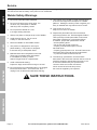
V(&'89*9%A&&7#-%A&&7#%)"$.%A.(**%S(&83%S7'3#
`KS(&83%S7'3%,89%R'$7*$
1. Tools marked with “Grounding Required” have
a three wire cord and three prong grounding
plug. The plug must be connected to a properly
grounded outlet. If the tool should electrically
malfunction or break down, grounding provides
a low resistance path to carry electricity away
from the user, reducing the risk of electric shock.
]?**%`KS(&83%S7'3%,89%R'$7*$1^
2. The grounding prong in the plug is connected
through the green wire inside the cord to the
grounding system in the tool. The green wire
in the cord must be the only wire connected to
the tool’s grounding system and must never
be attached to an electrically “live” terminal.
]?**%`KS(&83%S7'3%,89%R'$7*$1^
3. The tool must be plugged into an appropriate outlet,
properly installed and grounded in accordance
with all codes and ordinances. The plug and outlet
should look like those in the preceding illustration.
]?**%`KS(&83%S7'3%,89%R'$7*$1^
X&'+7*%C8#'7,$*9%A&&7#-%A&&7#%)"$.%A)&%S(&83%S7'3#
R'$7*$#%2&(%aKS(&83%S7'3
1. Tools marked “Double Insulated” do not
require grounding. They have a special
double insulation system which satisfies
OSHA requirements and complies with
the applicable standards of Underwriters
Laboratories, Inc., the Canadian Standard
Association, and the National Electrical Code.
2. Double insulated tools may be used in either of the
120 volt outlets shown in the preceding illustration.%%%
]?**%R'$7*$#%2&(%aKS(&83%S7'31^

Page 6 <&(%$*4.8"4,7%H'*#$"&8#I%/7*,#*%4,77%JKLLLKLMMKNOPO1 Item 96712
?@<6AQ RS6;@ACRE D@CEA6E@ET6?6AFS
6\$*8#"&8%T&(9#
1. Grounded tools require a three wire extension cord.
Double Insulated tools can use either
a two or three wire extension cord.
2. As the distance from the supply outlet increases,
you must use a heavier gauge extension cord.
Using extension cords with inadequately sized wire
causes a serious drop in voltage, resulting in loss of
power and possible tool damage. ]?**%A,+7*%@1^
3. The smaller the gauge number of the wire, the
greater the capacity of the cord. For example,
a 14 gauge cord can carry a higher current
than a 16 gauge cord. ]?**%A,+7*%@1^
4. When using more than one extension cord
to make up the total length, make sure
each cord contains at least the minimum
wire size required. ]?**%A,+7*%@1^
5. If you are using one extension cord for more
than one tool, add the nameplate%amperes
and use the sum to determine the required
minimum cord size. ]?**%A,+7*%@1^
6. If you are using an extension cord outdoors, make
sure it is marked with the suffix “W-A” (“W” in
Canada) to indicate it is acceptable for outdoor use.
7. Make sure the extension cord is properly wired
and in good electrical condition. Always replace
a damaged extension cord or have it repaired
by a qualified electrician before using it.
8. Protect the extension cords from sharp objects,
excessive heat, and damp or wet areas.
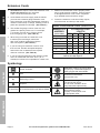
A@WG6%@-%%;6TRDD6EX6X%DCECDFD%UC;6%
V@FV6%<R;%6bA6E?CRE%TR;X?c%]Jad0aed%!RGA^
E@D6SG@A6
@DS6;6?
],$%2'77%7&,9^
6bA6E?CRE%TR;X%
G6EVAB
aNf Ndf ONf Jddf JNdf
0 – 2.0 18 18 18 18 16
2.1 – 3.4 18 18 18 16 14
3.5 – 5.0 18 18 16 14 12
5.1 – 7.0 18 16 14 12 12
7.1 – 12.0 18 14 12 10 -
12.1 – 16.0 14 12 10 - -
16.1 – 20.0 12 10 - - -
c%W,#*9%&8%7"5"$"83%$.*%7"8*%Y&7$,3*%9(&/%$&%2"Y*%Y&7$#%,$%
JNdg%&2%$.*%(,$*9%,5/*(*#1
?>5+&7&3>
Double Insulated
!
Volts
h
Alternating Current
@
Amperes
n
0
xxxx/min.
No Load Revolutions per Minute (RPM)
WARNING marking concerning Risk
of Eye Injury. Wear ANSI-approved
safety goggles with side shields.
Read the manual before
set-up and/or use.
WARNING marking
concerning Risk of Fire.
Do not cover ventilation ducts.
Keep flammable objects away.
WARNING marking concerning
Risk of Electric Shock.
Properly connect power cord
to appropriate outlet.

Page 7<&(%$*4.8"4,7%H'*#$"&8#I%/7*,#*%4,77%JKLLLKLMMKNOPO1Item 96712
?@<6AQRS6;@ACRED@CEA6E@ET6 ?6AFS
?/*4"2"4,$"&8#
Electrical Rating 120VAC / 60Hz / 1300W
Air Requirement 6.3 CFM
Tem pe ra tu re R an ge 105° to 850°
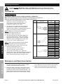
Nozzle Sizes
A. Angle Tip (1-3/4" L)
B. Curved/Rounded Tip (2-1/8" L)
C. Bent Tip (1-1/2″ L)
?*$'/%K%W*2&(*%F#*-
% ;*,9%$.*%6EAC;6%CDSR;A@EA%?@<6AQ%CE<R;D@ACRE%#*4$"&8%,$%$.*%+*3"88"83%&2%$."#%
5,8',7%"847'9"83%,77%$*\$%'89*(%#'+.*,9"83#%$.*(*"8%+*2&(*%#*$%'/%&(%'#*%&2%$."#%/(&9'4$1
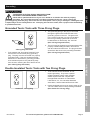
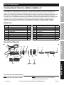
E&$*- For additional information regarding the parts listed in the
following pages, refer to Parts List and Diagram on page 11.
<'84$"&8#
W,((*7
E&ii7*%T
T(,97*
R80R22%?)"$4.
B,897*
E&ii7*%@
E&ii7*%@

Page 8 <&(%$*4.8"4,7%H'*#$"&8#I%/7*,#*%4,77%JKLLLKLMMKNOPO1 Item 96712
?@<6AQ RS6;@ACRE D@CEA6E@ET6?6AFS
R/*(,$"83%C8#$('4$"&8#
% ;*,9%$.*%6EAC;6%CDSR;A@EA%?@<6AQ%CE<R;D@ACRE%#*4$"&8%,$%$.*%+*3"88"83%&2%$."#%
5,8',7%"847'9"83%,77%$*\$%'89*(%#'+.*,9"83#%$.*(*"8%+*2&(*%#*$%'/%&(%'#*%&2%$."#%/(&9'4$1
A&&7%?*$%F/
AR%S;6!6EA%?6;CRF?%CEjF;Q%<;RD%@TTCX6EA@G%RS6;@ACRE-%
D,Z*%#'(*%$.,$%$.*%A("33*(%"#%"8%$.*%&22K/&#"$"&8%,89%'8/7'3%$.*%$&&7%2(&5%"$#%
*7*4$("4,7%&'$7*$%+*2&(*%/*(2&(5"83%,8>%/(&4*9'(*%"8%$."#%#*4$"&81
1. Determine if the finished product you are
welding is in need of a beveled edge. If so,
use a grinder or table saw (not included)
to bevel any edges to a 60° angle.
2. All materials to be welded must be cleaned of
any dirt, dust, or debris. If any oil substance
remains on the material, use Methyl Ethyl Ketone 9
(MEK) (not included) to clean the material.
ERA6- Make sure to read and understand
all instructions and precautions as
outlined by the MEK manufacturer.
3. The heat generated by the Plastic Welding Kit
can cause serious burns. Observe all Safety
Warnings and Precautions. Inspect the Plastic
Welder for signs of damage prior to each use.
4. Screw on the correct welding Nozzle.
ERA6- When welding two plastic sheets together
at 90°, use Nozzle #(1) for the tack weld first.
Then use Nozzle #(21) or #(22) for the line weld.
5. Set the Potentiometer (20) at “0”.
Then plug the Power Cord (19) into a
120 volt, grounded, electrical outlet.
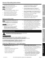
6. Turn on the Power Switch (14). Adjust the
Potentiometer (20) to reach the desired temperature
(see Figure A). Allow the Plastic Welder to warm
up for several minutes before starting to weld.
Part # Nozzle Type
Potentiometer
Setting
Output
21
Angle Nozzle 1 170°F
2 250°F
3 330°F
4 360°F
5 450°F
6 510°F
7 560°F
8 650°F
9 730°F
10 850°F
22
Curved Nozzle 1 130°F
2 190°F
3 290°F
4 370°F
5 390°F
6 490°F
7 550°F
8 630°F
9 700°F
10 770°F
1
Bent Nozzle 1 150°F
2 210°F
3 290°F
4 360°F
5 390°F
6 450°F
7 500°F
8 550°F
9 590°F
10 660°F
Output temperature readings taken at 90° surrounding temperature.
<"3'(*%@
U&(Z/"*4*%,89%U&(Z%@(*,%?*$%F/
1. Designate a work area that is clean and well lit.
The work area must not allow access by children
or pets to prevent distraction and injury.
2. Route the power cord along a safe route to reach
the work area without creating a tripping hazard or
exposing the power cord to possible damage. The
power cord must reach the work area with enough
extra length to allow free movement while working.
3. Secure loose workpieces using a vise or clamps
(not included) to prevent movement while working.
4. There must not be objects, such as utility lines,
nearby that will present a hazard while working.

Page 9<&(%$*4.8"4,7%H'*#$"&8#I%/7*,#*%4,77%JKLLLKLMMKNOPO1Item 96712
?@<6AQRS6;@ACRED@CEA6E@ET6 ?6AFS
V*8*(,7%R/*(,$"83%C8#$('4$"&8#
1. Make sure that the Trigger is in the
off-position, then plug in the tool.
ERA6- Practice the welding procedure on
scrap material before the workpiece.
ERA6- Rods or strips are not
necessary for tack welding.
2. Make sure the Nozzle is installed. Allow air
to run through the Nozzle to heat it up.
3. While waiting for the Nozzle to heat up,
position the workpiece to be welded.
4. Carefully apply the heated Nozzle to the
area or seams of plastic to be joined.
5. With small pieces, weld them just enough
to hold the pieces together. If the pieces
are large, you may need to weld along
the entire seam or connection point.
6. Avoid overheating tack points as doing so will
cause the plastic to warp, burn, or discolor.
Grind the tack points down to take off the edges.
7. When finished welding, set the Potentiometer to “0”.
Rest the Plastic Welder on its Cradle to keep the
hot Nozzle (1, 21, 22) from touching any surfaces.
8. Keep air flowing for five minutes after
disconnecting the electricity.
9. To prevent accidents, turn off the tool and
unplug it after use. Clean, then store the
tool indoors out of children’s reach.
U*79"83%)"$.%U*79"83%;&9#
ERA6- When welding with welding rods, use
the correct welding rod for the material being
welded. If welding vinyl, use a vinyl welding
rod. If welding PVC, use a PVC welding rod.
T@FACREk Never place a welding rod
inside the Nozzle (1, 21, 22).
1. Material up to 1/2" thick can be welded.
As different types of plastic material
will melt at different temperatures, the
Potentiometer must be properly adjusted.
2. Hold the Welder with one hand. With the other
hand, hold the welding rod. Hold the welding rod
close to the Nozzle (about 1/4" to 3/8" away).
3. You are now ready to begin the welding operation.
4. When finished welding, set the Potentiometer to
“0”. Rest the Plastic Welder on its Cradle to keep
the hot Nozzle from touching any surfaces.
5. IMPORTANT! Keep the air flowing for several
minutes to allow the Welder to cool.
Then close the air supply.
D,"8$*8,84*%,89%?*(Y"4"83
%S(&4*9'(*#%8&$%#/*4"2"4,77>%*\/7,"8*9%"8%$."#%5,8',7%5'#$%
+*%/*(2&(5*9%&87>%+>%,%H',7"2"*9%$*4.8"4",81
AR%S;6!6EA%?6;CRF?%CEjF;Q%<;RD%@TTCX6EA@G%RS6;@ACRE-%
D,Z*%#'(*%$.,$%$.*%A("33*(%"#%"8%$.*%&22K/&#"$"&8%,89%'8/7'3%$.*%$&&7%2(&5%"$#%
*7*4$("4,7%&'$7*$%+*2&(*%/*(2&(5"83%,8>%/(&4*9'(*%"8%$."#%#*4$"&81
AR%S;6!6EA%?6;CRF?%CEjF;Q%<;RD%ARRG%<@CGF;6-%
X&%8&$%'#*%9,5,3*9%*H'"/5*8$1%%C2%,+8&(5,7%8&"#*%&(%Y"+(,$"&8%
&44'(#I%.,Y*%$.*%/(&+7*5%4&((*4$*9%+*2&(*%2'($.*(%'#*1
T7*,8"83I%D,"8$*8,84*I%,89%G'+("4,$"&8
1. W6<R;6%6@TB%F?6I inspect the general
condition of the tool. Check for:
• loose hardware,
• misalignment or binding of moving parts,
• damaged cord/electrical wiring,
• cracked or broken parts, and
• any other condition that may
affect its safe operation.
2. T@;WRE%W;F?B%D@CEA6E@ET61
The carbon brushes may require maintenance when
the motor performance of the tool decreases or
stops working completely. To maintain the brushes:
a. Remove the Carbon Brush Cover on
each side of the motor housing.
b. Remove the carbon brushes from the
housing. [**/%$(,4Z%&2%)."4.%&("*8$,$"&8%
$.*%&79%4,(+&8%+('#.*#%)*(*%"8%$&%/(*Y*8$%
8**97*##%)*,(%"2%$.*>%)"77%+*%(*"8#$,77*91
c. If either carbon brush is worn down by
more than 1/2, replace them both.

Page 10 <&(%$*4.8"4,7%H'*#$"&8#I%/7*,#*%4,77%JKLLLKLMMKNOPO1 Item 96712
?@<6AQ RS6;@ACRE D@CEA6E@ET6?6AFS
d. To clean old carbon brushes before reusing
them, rub the contact areas with a pencil eraser.
e. Reinsert the old carbon brushes in the
same orientation to reduce wear.
f. When installing, make sure the carbon portions
of the brushes contact the motor armature,
and that the springs face away from the motor.
Also, make sure the springs operate freely.
g. Replace the Carbon Brush
Covers. Do not overtighten.
E&$*- New carbon brushes tend to
spark when first used until they wear and
conform to the motor’s armature.
3. @<A6;%F?6I wipe external surfaces
of the tool with clean cloth.
4. Always store the tool in a clean, dry,
safe location out of reach of children
and other unauthorized people.
T@FACREk All maintenance, service, and repairs
not mentioned in this manual must only be
performed by a qualified service technician.
5. U@;ECEVk%%C2%$.*%#'//7>%4&(9%&2%$."#%
/&)*(%$&&7%"#%9,5,3*9I%"$%5'#$%+*%(*/7,4*9%
&87>%+>%,%H',7"2"*9%#*(Y"4*%$*4.8"4",81
A(&'+7*#.&&$"83
S(&+7*5 S&##"+7*%T,'#*# G"Z*7>%?&7'$"&8#
Tool will not start. 1. Cord not connected.
2. No power at outlet.
3. Tool’s thermal reset breaker
tripped (if equipped).
4. Internal damage or wear.
(Carbon brushes or
Trigger, for example.)
1. Check that cord is plugged in.
2. Check power at outlet. If outlet is unpowered,
turn off tool and check circuit breaker.
If breaker is tripped, make sure circuit is right
capacity for tool and circuit has no other loads.
3. Turn off tool and allow to cool.
Press reset button on tool.
4. Have technician service tool.
Tool operates slowly. 1. Forcing tool to work too fast.
2. Extension cord too long or cord
diameter too small.
1. Allow tool to work at its own rate.
2. Eliminate use of extension cord. If an extension
cord is needed, use one with the proper diameter
for its length and load. See Extension Cords
in Grounding section on page 5.
Performance
decreases over time.
Carbon brushes worn or damaged. Have qualified technician replace brushes.
Excessive noise
or rattling.
Internal damage or wear. (Carbon
brushes or bearings, for example.)
Have technician service tool.
Overheating. 1. Forcing tool to work too fast.
2. Blocked motor housing vents.
3. Motor being strained by long or
small diameter extension cord.
1. Allow tool to work at its own rate.
2. Wear ANSI-approved safety goggles and
NIOSH-approved dust mask/respirator while
blowing dust out of motor using compressed air.
3. Eliminate use of extension cord. If an extension
cord is needed, use one with the proper diameter
for its length and load. See Extension Cords
in Grounding section on page 5.
Weld does not
penetrate joint.
1. Insufficient weld heat.
2. Incorrect fill material.
1. Increase potentiometer setting slightly.
2. Make sure that fill material is appropriate
for material being welded.
Plastic starts
to break down,
smoke, or burn.
Too much weld heat. Make sure to have adequate ventilation.
Decrease potentiometer setting slightly.
Unsatisfactory weld. Potentiometer not properly adjusted. Refer to the plastic material manufacturer’s manual
to determine the proper heat required. Then set
the Potentiometer to the proper heat setting.
% <&77&)%,77%#,2*$>%/(*4,'$"&8#%).*8*Y*(%9",38&#"83%&(%#*(Y"4"83%$.*%$&&71%%%
X"#4&88*4$%/&)*(%#'//7>%+*2&(*%#*(Y"4*1

Page 11<&(%$*4.8"4,7%H'*#$"&8#I%/7*,#*%4,77%JKLLLKLMMKNOPO1Item 96712
?@<6AQRS6;@ACRED@CEA6E@ET6 ?6AFS
S,($#%G"#$%,89%X",3(,5
SG6@?6%;6@X%AB6%<RGGRUCEV%T@;6<FGGQ
THE MANUFACTURER AND/OR DISTRIBUTOR HAS PROVIDED THE PARTS LIST AND ASSEMBLY DIAGRAM
IN THIS MANUAL AS A REFERENCE TOOL ONLY. NEITHER THE MANUFACTURER OR DISTRIBUTOR
MAKES ANY REPRESENTATION OR WARRANTY OF ANY KIND TO THE BUYER THAT HE OR SHE IS
QUALIFIED TO MAKE ANY REPAIRS TO THE PRODUCT, OR THAT HE OR SHE IS QUALIFIED TO REPLACE
ANY PARTS OF THE PRODUCT. IN FACT, THE MANUFACTURER AND/OR DISTRIBUTOR EXPRESSLY
STATES THAT ALL REPAIRS AND PARTS REPLACEMENTS SHOULD BE UNDERTAKEN BY CERTIFIED AND
LICENSED TECHNICIANS, AND NOT BY THE BUYER. THE BUYER ASSUMES ALL RISK AND LIABILITY
ARISING OUT OF HIS OR HER REPAIRS TO THE ORIGINAL PRODUCT OR REPLACEMENT PARTS
THERETO, OR ARISING OUT OF HIS OR HER INSTALLATION OF REPLACEMENT PARTS THERETO.
S,($#%G"#$
S,($ X*#4("/$"&8 l$>
1 Nozzle #C (Bent) 1
2 Barrel 1
3 Insulating Tube 1
4 Heating Element 1
5 Insulating Disk 1
6 Circuit Board Cover 1
7 Rubber Ring 1
8 Fan 1
9 Control Circuit Board 1
10 Fan Cover 1
11 Seal Rubber Ring 1
S,($ X*#4("/$"&8 l$>
12 Motor Housing 1
13 Motor Assembly 1
14 Power Switch/Cover Assembly 1
15 Carbon Brush Cap 2
16 Cord Sleeve 1
17 Power Switch Circuit Board 1
18 Carbon Brush 2
19 Power Cord 1
20 Potentiometer 1
21 Nozzle #A (Angled) 1
22 Nozzle #B (Curved/Rounded) 1
@##*5+7>%X",3(,5
J
a
`
e
N
M
O
L
P
Jd
JJ
Ja
J`
Je
JN
JM
JO
JL
JP
ad
aJ
aa
;*4&(9%S(&9'4$_#%?*(",7%E'5+*(%B*(*-%
E&$*-%C2%/(&9'4$%.,#%8&%#*(",7%8'5+*(I%(*4&(9%
5&8$.%,89%>*,(%&2%/'(4.,#*%"8#$*,91
E&$*- Some parts are listed and shown for
illustration purposes only, and are not available
individually as replacement parts.

`ePJ%D"##"&8%R,Z#%W7Y91%%m%%SR%W&\%MddP%%m%%T,5,("77&I%T@%P`dJJ%%m%%JKLLLKLMMKNOPO
G"5"$*9%Pd%X,>%U,((,8$>
Harbor Freight Tools Co. makes every effort to assure that its products meet high quality and durability standards,
and warrants to the original purchaser that this product is free from defects in materials and workmanship for the
period of 90 days from the date of purchase. This warranty does not apply to damage due directly or indirectly,
to misuse, abuse, negligence or accidents, repairs or alterations outside our facilities, criminal activity, improper
installation, normal wear and tear, or to lack of maintenance. We shall in no event be liable for death, injuries
to persons or property, or for incidental, contingent, special or consequential damages arising from the use of
our product. Some states do not allow the exclusion or limitation of incidental or consequential damages, so the
above limitation of exclusion may not apply to you. THIS WARRANTY IS EXPRESSLY IN LIEU OF ALL OTHER
WARRANTIES, EXPRESS OR IMPLIED, INCLUDING THE WARRANTIES OF MERCHANTABILITY AND FITNESS.
To take advantage of this warranty, the product or part must be returned to us with transportation charges
prepaid. Proof of purchase date and an explanation of the complaint must accompany the merchandise.
If our inspection verifies the defect, we will either repair or replace the product at our election or we may
elect to refund the purchase price if we cannot readily and quickly provide you with a replacement. We will
return repaired products at our expense, but if we determine there is no defect, or that the defect resulted
from causes not within the scope of our warranty, then you must bear the cost of returning the product.
This warranty gives you specific legal rights and you may also have other rights which vary from state to state.
-
 1
1
-
 2
2
-
 3
3
-
 4
4
-
 5
5
-
 6
6
-
 7
7
-
 8
8
-
 9
9
-
 10
10
-
 11
11
-
 12
12


Chicago Electric 96712 Owner's manual
- Category
- Power tools
- Type
- Owner's manual
- This manual is also suitable for
Ask a question and I''ll find the answer in the document
Finding information in a document is now easier with AI
Related papers
-
Chicago Electric Item 96464 Owner's manual
-
-
-
-
-
-
-
-
-
Other documents
-
Roadshock 12v Quick start guide
-
-
Vulcan Item 56254 Owner's manual
-
-
 Titanium Item 56221 Owner's manual
-
Harbor Freight Tools 80 Amp_DC, 120 Volt, Inverter Stick Welder User manual
-
-
-
-
Miller SPW 1 Owner's manual
