Page is loading ...

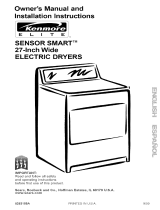
29-Inch Wide
ELECTRIC DRYERS
IMPORTANT:
Read and follow all safety
instructions and operating
instructions before first use
of this product.
r
f
Your dryer may look different
from the dryer shown.
Sears, Roebuck and Co., Hoffman Estates, IL 60179 U.S.A.
PART NO. 3405586 PRINTED IN U.S.A.

BEFORE USING YOUR NEW DRYER 2
SEARS ELECTRIC DRYER WARRANTY
IMPORTANT SAFETY INSTRUCTIONS
INSTALLATION INSTRUCTIONS
OPERATING YOUR DRYER
LAUNDRY TIPS
CARING FOR YOUR DRYER
TROU BLESHOOTING
SEARS MAINTENANCE AGREEMENT
REQUESTING ASSISTANCE OR SERVICE
4
20
27
30
33
35
36
Please read this manual. It will help you
install and operate your new Kenmore dryer
in the safest and most economical way.
For information about the care and
operation of Sears appliances call your
nearest Sears store. You will need the
complete model and serial numbers
when requesting information. Your dryer's
model and serial numbers are located
on the Model and Serial Number Plate.
Use the ,';pace below to record the
model nt,mber and serial number of
your new Kenmore Dryer.
Model No.
Serial No.
Date of Purchase
Keep this book and your sales
check (re,ceipt) in a safe place for
future reference.

FULL 1-YEAR WARRANTY
ON MECHANICAL AND
ELECTRICAL PARTS
For one year from the date of purchase,
when the dryer is installed and operated
according to the instructions in the Owner's
Manual, Sears will repair or replace any
mechanical or electrical parts in this dryer,
if defective in material or workmanship.
If the dryer is subjected to other than
private family use, the above warranty
coverage is effective for only 90 days.
WARRANTY SERVICE IS AVAILABLE
BY CONTACTING THE NEAREST
SEARS SERVICE CENTER IN THE
UNITED ST_,TES.
This warranty applies only while this
product is ir use in the Llnited States.
This warranty gives you specific legal
rights, and you may also have other
rights which vary from state to state.
Sears Roebuck and Co., Dept. 817WA,
Hoffman Fstates, IL 60179.
NOTE: Exhausting your dryer with
plastic duct may not be covered by your
manufacturer's warranty. Pages 16-18
of this Owner's Manual describe the
complete exhaust requirements for
this dryer.
YOUR SAFETY IS IMPORTANT TO US.
WARNING: To reduce the risk of fire,
electric shock, or injury to persons when
using your dryer, follow basic precautions,
including the following:
• Read all instructions before using the
dryer.
• Do not dry articles that have been
previously cleaned in, washed in, soaked
in, or spotted with gasoline, dry-cleaning
solvents, other flammable or explosive
substances as they give off vapors that
could ignite or explode.
• Do not allow children to play on or in
the dryer. Close supervision of children
is necessary when the dryer is used
near children.
• Before the dryer is removed from service
or discarded, remove the door to the
drying compartment.
• Do not reach into the dryer if the drum
is moving.
• Do not install or store this dryer where
it will be exposed to the weather.
• Do not tamper with controls.
• Do not repair or replace any part of the
dryer or attempt any servicing unless
specifically recommended in the user-
maintenance instructions or in published
user-repair instructions that you under-
stand and have the skills to carry out.
• Do not use fabric softeners or products
to eliminate static unless recommended
by the mar ufacturer of tlhe fabric softener
or product.
• Do not use heat to dry articles containing
foam rubber or similarly textured rubber-
like materials.
• Clean lint screen before or after each
load.
• Keep area around the e;<haust opening
and adjacent surrounding areas free from
the accumulation of lint, dust, and dirt.
• The interior of the machiine and exhaust
duct should be cleaned :periodically by
qualified service personnel.
This guide contains safety statements
under warning symbols. Please pay
special attention to the warning boxes
similar to the one below and follow
any instructions given,,
The information in this box will
alert you to such dangers as fire,
electrical shock, burns and
personalt injury.
SAVE THESE INSTRUCTIONS 3

IMPORTANT:
Observe all governing codes
and ordinances.
TOOLS NEEDED FOR INSTALLATION
j
Level
f
Tin
Snips
Flat-Bladed
Screwdriver
j#
,A,djustable
Screwdriver Wrench
Duct ]-ape
_Fe
Stripper
PARTS NEEDED FOR INSTALLATION
Remove leveling legs from package.
4 Leveling Legs
(supplied with dryer)
Strain relief
New 3- or 4-Wire, 30-Amp.
U.L.-listed Power Supply Cord
Kit (includes strain relief)
4-Inch Metal Elbow
(optional depending
on installation)
4-Inch Rigid or
Flexible Metal Duct
4-Inch Outlet
Exhaust Hood
(2) 4-Inch Diameter
Clamps
4

LOCATING YOUR DRYER -
STANDARD INSTALLATION
Selecting the proper location
for your dryer makes installation
easier and gives you the best
drying performance.
Protect from the weather. Proper
operation of dryer cycles requires
temperatures above 45°F. At lower
temperatures, the dryer may not shut
off at the end of automatic cycles.
Drying times will be extended.
Check code requirements. Some
codes limit or do not permit installation
of clothes dryers in garages, closets,
mobile homes or sleeping quarters.
Contact your local building inspector.
!
E_:plosion Hazard
Keep flammable materials and
vapors awa!_,from dryer.
Place dryer at least 18 inches above
the floor for a garage installation.
Failure to do so can result in death,
explosionk, fire, or burns.
Check location where dryer will be installed.
Proper installation is your responsibility.
Make sure you have everything necessary
for correct installation including support,
a level floor and a separate 30-amp. fuse.
I'
Separate
______ 30 amp fuse
['1I! Grounded receptacle:
IJI] --------, Within 2 feet of either
/ side of dryer.
Level floor: 1-inch
Support: Floor must be sturdy maximum allowable
enough to support dryer and
load weight of 175 pounds, slope under dryer.

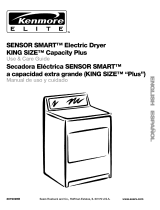
DOOR CLEARANCES
Location must be large enough to fully
open dryer door.
Large Side-SwingDoor
SuperWideSide-SwingDoor
'133/4"
Wide-OpeningHamperDoor

RECESSED AREAINSTRUCTIONS
This dryer may be installed in a recessed
area or closet.
Exhausting your dryer indoors is Not
recommended. The moisture and lint
indoors may cause:
• Lint to gather inside and around the
dryer and be a fuel for a fire.
• Moisture damage to woodwork, furniture,
paint, wallpaper, carpet, etc.
• Housecleaning problems and possible
health problems.
?
NOTE: No fuel burning appliances
may be installed in the same closet
as a dryer.
Exhausting the dryer outside is recom-
mended. A closet installation must be
exhausted outside. Recessed installation
that is not exhausted outside must use
Exhaust Deflector Kit Part No. 3391278
available from your dealer.
If the dryer is installed in a confined
area such as a bedroom, bathroom,
or closet, it rrust be exhausted to the
outside. Che{'k governing codes and
ordinances.
Fire Hazard
Exhaust dryer outside if installed
in a closet.
Use Exhaust Deflector Kit #3391278
if installed in a recessed area.
Failure to do so can result in death or fire.
OlO
19"
I I
**48 sq. in
minimum 11
ventilation " "_'_'_"_"
alea
D
**24 sq" in:_
mlmmum
ventilation
area
*0"---_ _ _ J_---'O" -_ 1"_ -'_**4"_--
RONTV,EW V,EW V,EW
iOOORN0TS.0W. 10OORS.0WNi 0O0RW,TH
MINIMUMINSTALLATIONSPACING,CLOSETINSTALLATIONMUSTBEEXHAUSTEO.
* ADDITIONALCLEARANCESFORWALL,DOORANDFLOORMOLDI_IGSMAYBEHEOU]RED.
** OPENINGIS MINIMUM FORCLOSETO00R. LOUVEREDDOORWITH EQUIVALENTAIR
OPENINGSIS ACCEPTABLE.
*** ADDITIONALSPACEIS NEEDEDWHENEXTERNALEXHAUSTELBOWISUSED.
3"
• The installation spacing is in inches
and is the minimum allowable.
• Additional spacing should be
considered for ease of installation
and servicing.
• If closet door is installed, the
minimum air openings in top and
bottom are required.
* Louvered coors with equivalent air open-
ings in top and bottom are acceptable.
Closet installation must be exhausted.
Other installations must use at least the
minimum dimensions indicated.
• Additional space for other appliances
to be installed in the area should be
considerecL

INSTALL LEVELING LEGS
Leveling your dryer correctly will
reduce operating noise and provide
improved drying performance.
STEP 1. Take two of the cardboard
corners from the carton. Place them
on the floor in back of the dryer.
STEP 2. Firmly grasp the body of the
dryer (not the top or console panel).
Gently lay it on its back on the card-
board corners.
STEP 3. With one of the legs in hand,
check the ridges for a diamond marking.
STEP 4. Start to screw the legs into the
holes by hand. Use an adjustable wrenct
or other type wrench to finish turning the
legs until you reach the diamond markin(
Later adjustment may be needed.
STEP 5. Now stand the ,dryer up. Slide
dryer onto cardboard and move dryer
close to its final location. Leave enough
room to connect the exhaust duct.
STEP 6. Remove cardboard from under
dryer. Check levelness of:dryer by placinL
level on _:opof the dryer, first side-to-side,
then front-to-back. If dryer is not level,
adjust the legs up or down. It may be
necessary to level the dryer after it is
moved into its final position.
8

MAKE ELECTRICAL CONNECTION
It is your responsibility:
• To contact a qualified electrical installer.
• To assure that the electrical installation
is adequate and in conformance with
National Electrical Code, ANSI/NFPA
70 - latest edition* and all local codes
and ordinances.
*Copies of the standards listed above
may be obtained from:
National Fire Protection Association
Batterymarch Park
Quincy, Massachusetts 02269
ELECTRICAL REQUIREMENTS
The proper electrical connection
ensures a safe installation that
meets local code requirements.
WARNING: This appliance must be
grounded. In the event of malfunction
or breakdown, grounding will reduce the
risk of electric shock by providing a path
of least resistance for electric current.
?
This dryer is manufactured with the
3-wire frame-grounding conductor
connected to the NEUTRAL (center)
of the wiring I_arness of the terminal.
block. Do Not have a fuse in the
neutral or grounding circuit. A fuse
in the neutral or grounding circuit
could result in an electrical shock.
If local codes do not permit this
type of connection, we recommend
a "Four-Wire Connection'.'
A three-wire or four-wire, single phase
120/240-volt, 60-Hz, AC-only, electrical
supply (or th'ee-wire or four-wire,
120/208-volt if specified on serial/rating
plate) is required on a separate 30-ampere
circuit, fused on both sides o1:the line.
A time-delay fuse or circuit breaker is
recommended.
A wiring diagram is located inside the
console.
ELECTRICAL CONNECTION OPTIONS
If Your Home Has:
A 3-wire electrical receptacle
(NEMA Type 10-30R)
And You Will Be Connecting To:
A U.L.-listed 120/240-volt minimum,
30-amp., dryer power supply cord*
3-wire direct
(NEMA Type 10-30R)
GoTo
This Page
A 4-wire electrical receptacle
(NEMA Type 14-30R)
4-wire direct _1
(NEMA Type 14-30R)
10 -A
A fused disconnect or circuit breaker boy* 11- B
A U.L.-listed 120/240-volt minimum,
30-amp., dryer power supply cord.
12-C
*If local codes do not permit the connection of a frame-grounding conductor
to the neutral wire, see the instructions on page 12.
A fused disconnect or circuit breaker boy. 14 - D

A. MAKE THREE-WIRE
ELECTRICAL CONNECTION
TO RECEPTACLE
If using a 3-wire power cord:
Electrical Shock Hazard
Turn power supply off before
connecting cord.
Use a new 30-ampere power supply
cord.
Plug into a grounded outlet.
Failure to follow these instructions
can result in death, fire, or electrical
shock.
=;
Do Not use an extension cord with
this dryer.
Do Not sonnect plug end of power
supply cord into a live receptacle
before connecting power supply cord
to dryer terminal block.
STEP 1. Turn power supply off.
STEP 2, Remove hold-down screw
and terminal block cover.
H01d-d0wnscrew
Local codes may permit the use of
a U.L.-listed, 120/240-volt minimum,
30-ampere, dryer power supply cord
kit (pigtail). Power supply cord should
be type SRD or SRDT and be at least
four feet long. The wires that connect
to the dryer must end with ring terminals
or spade terminals with upturned ends.
A 3/4"U.L.-listed strain relief must be
installed where the power supply cord
connects to the dryer. Do Not modify the
power supply cord plug. If it does not fit
the outlet, have a proper outlet installed
by a qualified electrician.
The power supply cord must have three,
No.-10 copper wires to match a three-
wire receptacle of NEMA Type 10-30R.
Three-wire
receptacle
(10-30R)
10
Terminalblockcover
STEP 3. Attach 3/4"U.L.-listed strain
relief (U..L. marking on strain relief) to
the hole below terminal block opening.
Put the power supply cord through the
strain relief.
STEP 4. Loosen or remove terminal block
screws. Connect the neutral wire (white
or center) of power supply cord under
the center screw of the terminal block.
STEP 5. Connect the other two wires
to outer terminal block screws using the
same method(s) described in STEP 4.
Tighten all terminal block screws firmly.
External ground
connector
Centersilver-c010red
terminalblockscrew
White
neutral
wire
Neutral
groundingwire
(green/yelluw)
Strain relief
3-Wire Connection with
Frame-Grounding Conductor

STEP6.Tightenthestrainreliefscrews.
STEP7. Inserttabofterminalblockinto
slotofthedryerrearpanel.Securecover
withhold-downscrew.
ContinueInstallation on Page 16.
B. MAKE THREE-WIRE
ELECTRICAL CONN ECTION
TO DIRECT WIRE
If making a direct wire connection:
Electrical Shock Hazard
Turn power supply off before
connecting wires.
Use 10 gauge solid copper wire.
Electrically ground dryer.
Failure to follow these instructions
can result in death, fire, or
electrical shock.
The dryer can be connected directly
to fused disconnect or circuit breaker
box with three-wire flexible armored
or non-metallic sheathed copper cable
(with grounding wire). All current-carrying
wires must be insulated.
A conduit connector must be installed at
junction box. Allow four feet of slack in the
line so dryer can be moved if servicing
is ever necessary.
STEP 1. Turn power supply off.
STEP la. Strip 31/2inches of outer
covering from end of cable. If using
3-wire cable with grounding wire, cut
the bare wire even with outer covering.
_-,-- 31/2"_
STEP 2. Remove hold-down screw
and terminal 13lock cover.
H01d-d0wnscrew
Termina;blockcover
STEP 3. Attach 3/4"U.L.-listed strain
relief (U.L. marking on strain relief) to
the hole below terminal block opening.
Put the direcl: wire cable tl_rough the
strain relief.
STEP 4. Loosen or remove terminal block
screws. Connect the neutral wire (white
or center) of direct wire cable under the
center screw of the terminal block.
Externalgroun[I
connector,_
Centersilver-c010red
terminalblockscrew
White
neutral
wire
Neutral! inding
wire (green/yell0w) Strainrelief
3-Wire Connection with Direct Wire
STEP 4a. Place the hook-shaped end
of the wire over the terminal block screw.
The open sicle of the hook should face
to the right. Squeeze hook end of wire
together to form a loop.
STEP lb. Strip 1 inch of insulation from
the end of each insulated wire. Shape
the end of each wire into a "U" shaped
hook.
11

i
\-
STEP 5. Connect the other two wires
to outer terminal block screws using the
same method(s) described in STEP 4a.
Tighten all terminal block screws firmly.
STEP 6. Tighten the strain relief screws.
STEP 7. Insert tab of terminal block
cover into slot of the dryer rear panel.
Secure cover with hold-down screw.
Continue Installation on Page 16.
ALTERNATE CONNECTION:
if local codes do NOT permit the
connection of a frame-grounding
conductor to the neutral wire:
Follow STEPS 1-7 for either Section A or
Section B with these required additions:
STEP 4. Remove the neutral grounding
wire (green/yellow wire) from external
grounding connector screw. Continue
with STEP 4.
External Neutral
ground groundingwire
connector (green/yellow)
Groundingpath
determinedbya
qualified electrician
Alternate 3-Wire Connection with
External-Grounding Conductor
STEP 8. Connect separate copper
grounding wire from external ground
connector to an adequate ground. If
codes permit and a separate grounding
wire is used, it is recommended that a
qualified electrician determine that the
grounding path is adequate.
Continue Installation on Page 16.
t
C. MAKE FOUR-WIRE
ELECTRICAL CONNECTION
TO RECEPTACLE
If using a 4-wire power cord:
Electrical Shock Hazard
Turn power supply off before
connecting cord.
Use a new 30-ampere power
supply cord.
Plug into a grounded outlet.
Failure to follow these instructions
can result in death, fire, or electrical
shock.
Local codes may perrnit the use of
a U.L.-.li_,ted, 120/240-volt minimum,
30-ampe.re, dryer power supply cord
kit (pigtail). Power supply cord should
be type SRD or SRD]- arid be at least
four feet long. The wires that connect
to the dr,!er must end with ring terminals
or spade terminals with upturned ends.
A 3/4"U.L.-listed strain relief must be
installed where the power supply cord
connects to the dryer. Do Not modify the
power sLpply cord plug. If it does not fit
the ouilel, have a proper outlet installed
by a qua ified electrician.
For mobile homes or other four-wire
install_.tions, the power supply cord
must have four, No.-10 copper wires
and match a four-wire receptacle of
NEMA Type 14-30R. The fourth wire
(groundirlg conductor) must be
identified with a green cover and the
neutral conductor by .awhite cover.
Four-wire receptacle
(14-,30R)
12

Do Not use an extension cord with
this dryer.
Do Not connect plug end of power
supply cord into a live receptacle before
connecting power supply cord to dryer
terminal block.
STEP 1. Turn power supply off.
STEP 2. Remove hold-down screw
and terminal block cover.
Hold-down
screw
Terminal block cover
STEP 3. Attach 3/4" U.L.-listed strain
relief (U.L. marking on strain relief) to
the hole below terminal block opening.
Put the power supply cord through
the strain relief.
STEP 4. Remove the center terminal
block screw. Remove the neutral ground-
ing wire (green/yellow wire) from exter-
nal grounding screw.
External ground
connector
Centersilver-colored
terminalblockscrew
STEP 5. Connect neutral grounding wire
and the neutral wire (white) of power
supply corc under the center screw of
terminal block.
STEP 6. Connect the other two insulated
wires to outer terminal block screws. Use
the same method descriibed in STEP 4.
STEP 7. Connect the green, grounding
wire from the power supply cord to the
external grounding conductor screw.
Tighten all :erminal block screws firmly.
STEP 8. Tighten the strain relief screws.
STEP 9. Insert tab of terminal block
cover into slot of the dryer rear panel.
Secure cover with hold-down screw.
Centersilver-
External coloredlerminal Whiteneutral
ground blockscrew wire
connector
Greenwire Neutral
of powersupply groundingwire
cordor bare (green/yellow)
copperwire
Strainrelief
4-Wire Connection with
Frame-Grounding Conductor
Continue Installation on Page 16.
Green/yellow wire
of harness

D. MAKE FOUR-WIRE
ELECTRICAL CONNECTION
TO DIRECT WIRE
If making a direct wire connection:
Electrical Shock Hazard
Turn power supply off before
connecting wires.
Use 10 gauge solid copper wire.
Electrically ground dryer.
Failure to follow these instructions
can result in death, fire, or electrical
shock.
The dryer can be connected directly to
fused disconnect or circuit breaker box
with four-wire flexible armored or non-
metallic sheathed copper cable (with
grounding wire). All current-carrying
wires must be insulated.
A conduit connector must be installed
at junction box. Allow four feet of slack
in the line so dryer can be moved if
servicing is ever necessary.
STEP 1. Turn power supply off.
STEP la. Strip 5 inches of outer covering
from end of cable. Leave bare grounding
wire at 5 inches.
STEP 2, Remove hold-down screw
and terminal block cover.
Hold-down
screw
Terminalblockcover
STEP 3. Attach 3/4"U.L.-listed strain
relief (U.L. marking on strain relief) to
the hole below terminal block opening.
Put the clirect wire cable through the
strain relief.
STEP ,4. Remove the center terminal
block _;crew. Remove the neutral ground-
ing wire (green/yellow wire) from external
grouncing screw.
Externalground
connector
Centersilver-colored
terminal blockscrew
5"
STEP 1b. Strip 1_/2inches from
3 remaining insulated wires. Strip
insulation back 1 inch. Shape the end
of each wire into a "U" shaped hook.
---11/2"
Green/yellowwire
ofharness
14

STEP 5. Connect neutral grounding wire
and the neutral wire (white or center) of
direct wire cable under the center screw
of terminal block.
Center silver-colored
terminal block screw
Externalground
connector
White neutral wire
Barecopperwire
4-Wire Connection
with Direct Wire
Neutral
groundingwire
(green/yellow)
Strain relief
STEP 6. Place the hook-shaped end of
the wire over the terminal block screw.
The open side of the hook should face
to the right. Squeeze hook end of wire
together to form a loop.
STEP 7. Connect the other two wires
to outer terminal block screws. Use
the same method described in STEP 6.
STEP 8. Connect the direct wire cable
(bare) grounding wire to the external-
grounding conductor screw. Tighten all
terminal blo,_k screws firmly.
STEP 9. Tighten the strain relief screws.
STEP 10. Irsert tab of terminal block
cover into stot of the dryer rear panel.
Secure cow._r with hold-down screw.
Continue Installation on Page 16.
15

CONNECT EXHAUST
• Replace plastic exhaust duct with
rigid metal or flexible metal duct.
• If using an existing exhaust system,
clean lint from entire length of exhaust
system. Make sure exhaust hood is
not plugged with lint.
A properly exhausted dryer will give
you the shortest drying time, lower'
your utility bill and extend the life of
the dryer.
Typical installations
for rear exhausting -
straight
(see p. 18)
\ 4
Avoid pushing the dryer tightly against
a wall. This can crush or kink the duct.
Use the straightest path you can, where
possible, to avoid 90 ° turns.
Fire Hazard
Use a heavy metal vent.
Do not use a plastic vent.
Do not use a metal foil vent.
Failure to do so can result in death
or fire.
° Do Not use non-metal flexible duct,
metal duct that is smaller than four
inches in diameter or exhaust hoods
with magnetic latches.
• Do Not exhaust dryer into a chimney,
furnace cold air duct, attic or crawl space,
or any other duct used for venting.
• Do Not install flexible duct in enclosed
walls, ceilings or floors.
Typical installations exhaust from the
rear of the dryer.
Typical installations
for rear exhausting -
offset
(see pgs. 16-18)
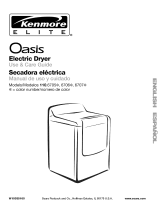
OFFSET CONNECTIONS
Maximum Exhaust Lengths:
• The maximum length of the rear exhaust
system depends on the type of duct,
the number of elbows and the type of
exhaust hood. Refer to the chart below.
EXHAUST HOOD TYPE
Number of
90° Turn.,;
0
1
2
3
4
0
1
2
3
4
__ 9_"
Maximum length of 4-inch
diameter rigid metal duct.
64 ft. 58 ft.
54 ft. 48 ft.
44 ft. 38 ft.
35 ft. 29 ft.
27 ft. 21 ft.
Maximum length of 4-inch
diameter flexible metal duct.
36 ft. 28 ft.
31 ft. 23 ft.
27 ft. 19 ft.
25 ft. 17 ft.
23 ft. 15 ft.
16

Using 4-inch rigid metal duct:
NOTE: DO NOT secure exhaust duct
joints with screws. Screws can catch
lint and slow the drying process.
STEP 1. Install a 4-inch metal elbow on
the hood and on the dryer exhaust outlet.
STEP 2. Measure the length of 4-inch
metal duct needed to connect the two
elbows.
Rigid ...
metal
duct
Dryer
Elbow
i •
Ducttate &
clamls
j Wall
_IExhaust
hood
\ _ Duct
_ tape &
clamps
\
STEP 2
_Elbow
The duct usually comes in 2-foot lengths.
Cut 2 inches longer than measurement
for connection.
STEP 3. Connect elbow to dryer outlet.
Tape the joint with duct tape. Tighten
clamp.
Tape
Clamp
STEP 4. Connect rigid metal duct to
elbow. Tape the joint with duct tape.
Tighten clamp.
STEP 5. Install one end of elbow on rigid
metal duct, the other end to the exhaust
hood. Tape joints and tighten clamps,
Continue Installation on Page 19.
Using 4-inch flexible metal duct:
NOTE: Do NOT secure exhaust duct
joints with screws. Screws can catch lint
and slow the drying process. ,,
STEP 1. Install a 4-inch metal elbow on
the hood and on the dryer exhaust outlet
if necessary (optional).
metalduct
Elbow
(optional)
Flexible \
Dryer
\
Ducttape &clamp
Wall
tape&
clamp
""STEP 2
Elbow
STEP 2. Me_sure the length of 4-inch
flexible metal duct needed from the dryer
to the hood.
STEP 3. Add 10 inches to the measure-
ment for each bend in the duct.
STEP 4. Add 2 more inches to the
measureme qt for connection over the
dryer outlet and hood.
STEP 5. Install one end of elbow on
flexible metal duct, the other end to the
exhaust hood. Tape joints and tighten
clamps.
Tape
Clamp
STEP 6. Stretch the duct only as
needed by pulling out from the center
in each direction. Do not stretch duct
sections ow_r 6 feet. If distance is more
than 6 feet, use 2 or more sections of
rigid metal duct with flexible metal duct
attached at ends.
17

STEP 7. Connect the duct to the dryer
outlet and to the hood or to the elbows.
Tape the joint with duct tape. Secure
with clamps.
STEP 8. To fit the flexible metal duct
over the duct on the hood it may be
necessary to make two I/2-inch cuts in
the end of the flexible duct to allow it
to expand.
Continue Installation on Page 19.
Cut 2 inches longer than measurement
to fit over dryer and hood connections.
STEP 2. Side large end of the duct on
the dryer connection and the small end
on the hood connection. To prevent air
leakage, tape the joint with duct tape.
Clamp all joints.
STRAIGHT CONNECTIONS
NOTE: DO NOT secure exhaust duct
joints with screws. Screws can catch
lint and slow the drying process.
Dryer
\
/-
Rigid
metal
duct /
.-Wall
STEP 1
/
_ Exhausthood
J
Ducttape&clamps
Continue Installation on Page 19.
Dryer
\
/1
-! F-
Flexible
metal
duct
,_\%
• "-.,,,,/
Ducttape&clamps
iWall
STEP 1
/
f _
Exhaust
STEP 1. Measure the length of 4-inch
straight duct needed. The duct usually
comes in 2-foot lengths.
18

FINISH INSTALLATION/
CHECKPOINTS
Taking a few minutes to complete
this checklist will help ensure a
proper installation and increase your
satisfaction with Kenmore dryers.
/
[]
[]
[]
[]
[]
[]
D
Check that all parts you removed
from the parts packages are now
installed.
Carefully slide dryer into its final
location.
Check to be sure dryer is level
by placing level on top of the dryer,
first side-to-side then front-to-back.
If dryer is not level, adjust the legs
up or down.
Check to make sure you have all
the tools you started with.
Plug the power supply cord into the
grounded outlet or connect direct
wire to power supply. Turn power
supply on.
Wipe the interior of the drum
thoroughly with a damp cloth to
remove any dust.
Read the rest of this manual to fully
understand your new dryer. Start the
dryer and allow it to complete a full
heat cycle (not the air cycle). You
may notice a burning odor, This smell
is common when the heating element
is first used. The smell will go away.
After five minutes, open dryer door.
You should feel heat inside the dryer.
If you do not feel heat, see Trouble-
shooting information on pages 33-34•
19

STARTING YOUR DRYER
Explosion Hazard
Never place items in the dryer that
are dampened with gasoline or other
flammable fluids.
Do not wash or dry items soiled
with vegetable or cooking oils
because they may contain some
oil after laundering.
Doing so can result in death,
explosion, or fire.
To get the best drying results, you must
operate ycur dryer properly. This section
gives you _:hisimportant information.
Page references are included for more
informaLion.
The drawings in this section are
designed to show the different features
of all models covered by this manual.
Refer to the supplied "Feature Sheet"
for your dryer's features.
STEP 1. Check lint screen Clean
if needed.
STEP 2. Put laundry into dryer and
shut door.
STEP 3. Set Cycle Selector Control
(Timer) (9; (see pages 21-22).
STEP 4. Set FABRIC/Temperature
Control (_ if available; (see page 23).
Check clothes label for manufacturer's
recommendations.
STEP 5. Press PUSH TO START
Button (_)-- be sure door is closed.
FABRIC SIGNAL PUSH TO START
2O
STOPPING/RESTARTING
YOUR DFiYER
• To stop the dryer at any time, open
dryer doc r.
• Press the PUSH TO START Button
to restart.
• If you wish to end your drying cycle,
turn timer to OFF.
/