Page is loading ...

DualBrite
®
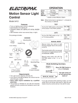
Motion Sensor
Light Control
Light Control
2 Lamps
(installed)
Cover Plate
Sensor
Lamp Holders
This package includes:
TEST
TEST 1 5 20
ON-TIME
Off 3 6 Dusk to
Dawn
DualBrite
®
Put ON-TIME switch
on the sensor bottom
to TEST and the Dual-
Brite
®
switch OFF.
OPERATION
* resets to Auto Mode at dawn.
ON-TIME
TEST 1 5 20
... back on.
1 Second OFF
then...
Put the ON-TIME switch in the 1, 5,
or 20 minute position.
Manual mode only works at night
because daylight returns the sensor
to AUTO.
Flip the light switch off for one second
then back on to toggle between AUTO
and MANUAL MODE.
Manual mode works only with the
ON-TIME switch in the 1, 5, or 20
position.
Note: When first turned on wait about 1
1
/
2
minutes for
the circuitry to calibrate.
Requirements
• The light control requires 120-volts AC.
• If you want to use Manual Mode, the control must be
wired through a switch.
• Some codes require installation by a
qualified electrician.
• This product is intended for use with the enclosed
gasket and with a junction box marked for use in wet
locations.
Mode: On-Time Works: Day Night
Test
5 Seconds x x
Auto
1, 5, or 20 Min x
Manual
To Dawn* x
Accent
3, 6 Hr, to Dawn x
AUTO
MANUAL MODE
Features
• DualZone™ Technology.
• Turns on lighting when motion is detected.
• Automatically turns lighting off.
• DualBrite
®
Timer.
• Photocell keeps the lighting off during daylight hours.
• LED indicates motion was sensed (day or night).
Plastic Hanger
Rubber Plug
Gasket
6 Screws
(3 sizes included)
Mounting Strap
Mounting Bolt
2 Wire
Connectors
598-1325-00
LPG-5597
®
Operating Instructions & Parts Manual 2LBL3, 2LBL4
HEA 009
Printed in China
09/07
Please read and save these instructions. Read carefully before attempting to assemble, install, operate or main-
tain the product described. Protect yourself and others by observing all safety information. Failure to comply
could result in personal injury and/or property damage! Save these instructions for future reference.

2
598-1325-00
CAUTION: To Avoid Fire Or Burn Hazards:
• Allow fixture to cool before touching. The bulb and
the fixture operate at high temperatures.
• Keep fixture at least 2" (51 mm) from combustible
materials. Do not aim at objects closer than 3' (1 m).
• Use only T4 100W (max.), G8 tungsten halogen
bi-pin 120 VAC lamps.
Move ON-TIME Switch
to 1, 5, or 20 minutes
Mode Switching Summary
Flip light switch
off for one second
then back on*
MANUAL MODE
AUTO
TEST
* If you get confused while switching modes, turn the
power off for one minute, then back on. After the cali-
bration time the control will be in the AUTO mode.
DualBrite
®
Timer
Light comes on half bright for selected time after dusk
(Off, 3 hr., 6 hr., until dawn). Selecting OFF disables
this feature. The motion sensing features will continue
to work as described in this manual. If motion is sensed,
the light turns on full bright for the ON-TIME (1, 5, or
20 minutes) then returns to dim mode.
INSTALLATION
For easy installation, select an existing light operated
by a wall switch for replacement.
For best performance, mount the fixture about 8 ft. (2.4 m)
above the ground.
NOTE:
If fixture is mounted higher than
8 ft. (2.4 m), aiming the sensor down will reduce coverage
distance.
CAUTION: Keep the sensor at least 2" (51 mm)
away from the lamps.
CAUTION: For under eave installation, the
sensor head must be rotated as shown in the next
two steps for proper operation and to avoid the risk of
electrical shock.
❒ Swing the sensor head towards the clamp screw.
For eave mount only:
❒ Rotate the sensor head clockwise 180° so the
controls face down.
Controls
Clamp Screw
If the sensor pops out of the ball joint, loosen the
clamp screw and push the sensor back into the ball
joint. Tighten the clamp screw when done.
Controls
Controls

3
598-1325-00
Keep lamps at least 2" (51 mm) from the
sensor and 2" (51 mm) from combustibles.
Lock Nuts
Mount the Light Control
❒ Place the mounting bolt through the front of the
junction box cover. Push the small gasket hole over
the mounting screw.
❒ Make sure the wire connectors and wires are inside
the junction box. Align the mounting screw with the
center hole in the mounting strap. Secure the fixture
to the mounting strap.
❒ Push the rubber plug firmly into place.
❒ If a wet location junction box was not used, caulk
the wall plate mounting surface with silicone weather
sealant.
Lamp Shade
Set Screw
Bulb Installation
NOTE: When re-lamping, turn power off and let the
fixture cool.
❒ To remove lamp shade, loosen set screw 2 full
turns with a small flat-head screwdriver. Turn shade
counterclockwise and remove.
❒ To remove bulb, pull straight out of fixture.
❒ To replace bulb, push bulb pins into lamp socket.
Check that the bulb is seated properly.
❒ To reinstall lamp shade, place shade on fixture and
align notches on shade with tabs on fixture. Turn
clockwise. Tighten set screw firmly.
❒ Adjust the lamp holders by loosening the lock nuts,
but do not rotate the lamp holders more than 180°
from the factory setting.
❒ Adjust lamp shades by loosening the set screws
several turns, turn shades counterclockwise and
remove. Reinstall the shades in the desired position
and tighten set screws.
❒ Remove the existing light fixture.
❒ Install the mounting strap as shown using two screws
that fit your junction box.
❒ The plastic hanger can be used to hold the fixture
while wiring. The small end of the plastic hanger
can be threaded through the hole in the center of
the cover plate. The small end then goes into one
of the slots on the mounting strap.
❒ Route the light control’s wires through the large
gasket holes.
❒ Twist the junction box wires and fixture wires together
as shown. Secure with wire connectors.
White to
White
Black to
Black
Junction box ground wire to
green ground screw on fixture.
Gasket
Mounting
Strap
Mounting
Bolt
Rubber
Plug
Wire the Light Control
WARNING: Turn power off at circuit breaker
or fuse.

4
598-1325-00
Bottom of Sensor
Avoid aiming the control at:
• Objects that change temperature rapidly, such as
heating vents and air conditioners. These heat
sources could cause false triggering.
• Areas where pets or traffic may trigger the control.
• Nearby large, light-colored objects reflecting light
may trigger the shut-off feature. Do not point other
lights at the sensor.
MAX
MIN
RANGE
ON-TIME
DUAL BRITE™
TEST 1 5 20
MINUTES
OFF
3
6
DUSK TO
DAWN HOUR
B
O
O
S
T
TEST AND ADJUSTMENT
❒ Turn on the circuit breaker and light switch.
NOTE: Sensor has a 1
1
/
2
minute warm up period
before it will detect motion. When first turned
on, wait 1
1
/
2
minutes.
❒ Turn the RANGE control to the medium position
(halfway between MIN and MAX), DualBrite
®
to OFF,
and the ON-TIME control to the TEST position.
❒ Loosen the clamp screw in the
sensor ball joint and gently
rotate the sensor.
❒ Walk through the coverage
area noting where you are
when the lights turn on (also,
the LED will flash several
times when motion is detect-
ed). Move the sensor head up,
down, or sideways to change
the coverage area. Keep the
sensor at least 2" (51 mm)
away from the lamps.
❒ Adjust the RANGE as needed.
RANGE set too high may
increase false triggering.
❒ Secure the sensor head
by tightening the clamp
screw. Do not overtighten the
screw.
❒ Set the amount of TIME you want the lights to stay
on after motion is detected (1, 5, or 20 minutes).
❒ Set the DualBrite
®
switch to the amount of time after
dusk you want the lights on at low level (Off, 3, 6
Hrs., Dusk-to-Dawn).
WARNING - Risk of fire. Do not aim the bulbs
at a combustible surface within 3 ft. (1 m).
Maximum
Maximum Range Coverage Angle
15 ft.
(4.6 m)
70 ft. 100 ft.
(21 m) (30.5 m)
Boosted
240°
DualZone™
DualZone™
Clamp
Screw
Ball
Joint
Aim Sensor
Down for Short
Coverage
Aim Sensor
Higher for Long
Coverage
Motion
Motion
Sensor
DualZone™DualZone™
NOTE: DualZone™ adds a zone of detection under
the motion sensor. DualZone™ requires no additional
adjustment and operates in conjuction with the for-
ward-looking sensor.
Least Sensitive Most Sensitive
NOTE:
If fixture is mounted higher than 8 ft. (2.4 m), aiming
the sensor down will reduce coverage distance.
The detector is less sensitive to motion directly towards it.

5
598-1325-00
SPECIFICATIONS
Horizontal Range . . . . Up to 70 ft. (21 m); 100 ft.
(30.5 m) with Range Boost.
[varies with surrounding
temperature]
Vertical Range . . . . . . Up to 15 ft. (4.6 m)
Sensing Angle . . . . . . Up to 240° horizontal. Up to 80°
Vertical
Electrical Load . . . . . . Up to 200 Watts Maximum In-
candescent (Up to 100 Watts
Maximum each lamp holder.)
Power Requirements . 120 VAC, 60 Hz
Operating Modes . . . . TEST, AUTO and MANUAL
MODE
Time Delay . . . . . . . . 1, 5, 20 minutes
DualBrite
®
Timer . . . . Off, 3, 6 hours, Dusk-to-Dawn
Replacement lamp . . . T4 100W, G8 halogen bi-pin 120
VAC
POSSIBLE CAUSE
1. A lamp is positioned too close to the
sensor or pointed at nearby objects
that cause heat to trigger the sensor.
(Reposition the lamp away from the
sensor or nearby objects).
2. Light control is pointed toward a heat
source like an air vent, dryer vent, or
brightly-painted heat-reflective surface.
(Reposition sensor. Reduce Range).
3. Light control is in Manual Mode. (Switch
to Auto).
1. Heat or light from the lamps may be
turning the light control on and off.
(Reposition the lamps away from the
sensor).
2. Heat being reflected from other objects
may be affecting the sensor. (Reposi-
tion sensor).
3. Light control is in the Test mode and
warming up. (Flashing is normal under
these conditions. Turn Boost off).
1. Sensor is detecting its own lights.
(Reposition lamps to keep area below
the sensor relatively dark).
SYMPTOM
Lights stay
on continu-
ously.
Lights flash
on and off.
Lights flash
once, then
stay off in
Manual Mode.
SYMPTOM
Lights will
not come
on.
Lights come
on in day-
light.
Lights come
on for no
apparent
reason.
Lights turn
off too late
in Dusk-
to-Dawn
setting.
POSSIBLE CAUSE
1. Light switch is turned off.
2. Light is loose or burned out.
3. Fuse is blown or circuit breaker is turned
off.
4. Daylight turnoff is in effect (recheck after
dark).
5. Incorrect circuit wiring, if this is a new
installation.
6. Re-aim the sensor to cover desired area.
1. Light control may be installed in a rela-
tively dark location.
2. Light control is in Test. (Set control switch
to an ON-TIME position).
1. Light control may be sensing small
animals or automobile traffic (re-aim
sensor).
2. Range is set too high. (Reduce Range
setting).
3. D
ualBrite
®
Timer is on.
1. Sensor is in a relatively dark location.
(Relocate sensor, or use 3 hr or 6 hr
setting).
TROUBLESHOOTING GUIDE
1 YEAR LIMITED WARRANTY:
Should this product fail to perform satisfactorily due to a defect or poor workmanship within one year of date of
purchase, return it to the place of purchase and it will be replaced, free of charge. Incidental or consequential
damages are excluded from this warranty. Light bulbs are not covered.
Manufactured for Grainger International, Inc.
Lake Forest, IL 60045
/