
DOWNDRAFT
USE AND CARE
MANUAL
MODELS: CVS2
MODELS: UCV2
DOWNDRAFT
USE AND CARE MANUAL
MODEL: HMCN 36 FS / 42 FS
VENTILATION
INSTALLATION MANUAL
Page is loading ...

3
WARNING
TO REDUCE THE RISK OF FIRE,
ELECTRIC SHOCK, OR INJURY TO
PERSONS, OBSERVE THE
FOLLOWING:
A. Installation work and electrical wiring
must be done by qualified person(s) in
accordance with all applicable codes
and standards, including fire-related
construction.
B. Sufficient air is needed for proper
combustion and exhausting of gases
through the flue (chimney) of fuel
burning equipment to prevent back-
drafting. Follow the heating equip-
ment manufacturer’s guideline and
safety standards such as those
published by the National Fired
Protection Association (NFPA), and
the American Society for Heating,
Refrigeration and Air Conditioning
Engineers (ASHRAE), and the local
code authorities.
C. When cutting or drilling into wall or
ceiling, do not damage electrical
wiring and other hidden utilities.
D. Ducted fans must always be vented
to the outdoors.
E. Always unplug or disconnect the
appliance from the power supply
before servicing.
F. This unit is designed for indoor use
only. Use this unit only in the manner
intended by the manufacturer.
WARNING
For general ventilating use only. Do not
use to exhaust hazardous or explosive
materials and vapors.
To reduce risk of fire and to properly
exhaust air, be sure to duct air outside.
Do not vent exhaust air into spaces
within walls, ceilings, attics, crawl spaces
or garages.
TO REDUCE THE RISK OF FIRE, USE
ONLY METAL DUCT WORK.
To reduce the risk of fire or electric
shock, do not use the fan with any solid-
state speed control device.
This appliance has been found to be in
compliance with UL 507 Standard for
Electric Fans and CAN/CSA-22.2 No.
113 Canadian Standard for Fans and
Ventilators. It is the responsibility of the
owner and the installer to determine if
additional requirements or standard
apply in specific installation.
SAFETY INSTRUCTIONS
Read All Instructions Before Using the Appliance.
READ AND SAVE THESE INSTRUCTIONS
Parts Needed
❑ Tape Measure
❑ Phillips Head Screwdriver
❑ Duct Tape
❑ Ductwork (configuration varies
depending on location; see ”Prior to
installation”).
❑ Additional Sheetmetal screws
(as necessary for ductwork installation)
Parts Supplied
❑ Appliance assembly (1)
❑ Sheetmetal Screws (6)
❑ Wood Screws (4)
❑ Counter Sink Screws (2)
❑ Hardware for brackets on vent (2)
❑ Plugs UX6 (6)

4
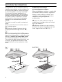
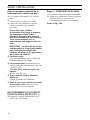
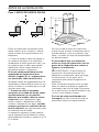
Fig. 1
GAS
ELECTRIC
IMPORTANT INFORMATION
Old appliances are not worthless rubbish.
Valuable raw materials can be reclaimed by
recycling old appliances. Before disposing
of your old appliance, render it unusable.
You received your new appliance in a
protective shipping carton. All packaging
materials are environmentally friendly and
recyclable. Please contribute to a better
environment by disposing of packaging
materials in an environmentally-friendly
manner.
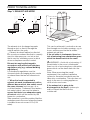
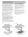
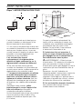
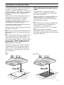
The hood can only be used in exhaust air
mode.
Always mount the hood over the center of
the cooking surface.
Minimum distance between electric
cooktop and bottom edge of hood: 30”,
Fig. 1.
The hood must not be installed over a
wood or coal burning stove – a potential fire
hazard (e.g. flying sparks) – unless the stove
features a closed, non-removable cover
and all national regulations are observed.
The smaller the gap between the hood and
cooktops, the greater the likelihood that
droplets will form on the underside of the
hood.
Additional information
concerning gas cookers:
When installing gas cooktops, comply with
the relevant national statutory regulations.
Always comply with the currently valid
regulations and installation instructions
supplied by the gas appliance
manufacturer.
Only one side of the hood may be
installed next to a high-sided unit or high
wall. Gap at least 2”.
Minimum distance on gas cooktops
between the upper edge of the grate and
lower edge of the hood: 30”, Fig. 1.

5
The exhaust air is discharged upwards
through a duct or directly through the
outside wall into the open.
D
Exhaust air should neither be directed
into a smoke or exhaust flue that is currently
used for other purposes, nor into a duct
that is used for ventilating rooms in which
stoves or fireplaces are also located.
Exhaust air may be discharged in
accordance with official and statutory
regulations only (e.g. national building
regulations).
Local authority regulations must be
observed when discharging air into smoke
or exhaust flues that are not otherwise in
use.
D
When the hood is operated in
exhaust-air mode simultaneously with a
different burner which also makes use of
the same chimney (such as gas, oil or
coal-fired heaters, continuous-flow heaters,
hot-water boilers) care must be taken to
ensure that there is an adequate supply
of fresh air which will be needed by the
burner for combustion.
Safe operation is possible provided that the
underpressure in the room where the burner
is installed does not exceed 4 Pa (0.04
mbar).
This can be achieved if combustion air can
flow through non-lockable openings, e.g. in
doors, windows and via the air-intake/
exhaust-air wall box.
If the air intake is inadequate, there is a
risk of poisoning from combustion gases
which are drawn back into the room.
WARNING – Avoid risk of poisoning – If
the air intake to the room is inadequate,
there is a risk of poisoning from combustion
gases which can be drawn back into the
room.
Note: When assessing the overall
requirement, the combined ventilation
system for the entire household must be
taken into consideration. This rule does not
apply to the use of cooking appliances,
such as hobs and ovens.
If the exhaust air is going to be
discharged into the open, a telescopic
wall box should be fitted into the
outside wall.
PRIOR TO INSTALLATION
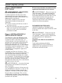
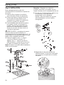
Step 1: EXHAUST-AIR MODE
8"
8"

6
For optimum hood efficiency:
❑ Short, smooth duct pipe.
❑
As few bends in the ducting as possible.
❑
Diameter of ducting to be as large as
possible and no tight bends in ducting.
If long, rough exhaust-air ducting,
many ducting bends or smaller pipe
diameters are used, the air extraction
rate will no longer be at an optimum
level and there will be an increase in
noise.
IMPORTANT: The manufacturer of the
hood accepts no liability for
complaints which can be attributed to
the design and layout of the duct-
work.
❑
Round pipes:
We recommend
Internal diameter: 8”.
❑
Flat ducts must have an internal cross-
section that equates to that of round
pipes.
There should be no sharp bends.
l 8” approx. 50.3 inches
2
❑
If pipes have different diameters:
Insert sealing strip.
❑
For exhaust-air mode, ensure that
there is an adequate supply of fresh air.
CONNECTING A l 8” EXHAUST-AIR
DUCT:
❑ Mount the duct directly onto the air out-
let on the hood.
Step 2: PREPARING THE WALL
❑ The wall must be flat and perpendicular.
❑
Ensure that the wall is capable of
providing a firm hold for mounting
screws and plugs.
Weight in kg: 23.0
PRIOR TO INSTALLATION

7
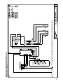
Step 3: ELECTRICAL CONNECTION
WARNING: THIS APPLIANCE MUST
BE GROUNDED
The hood should only be connected to a
grounded socket that has been installed
according to relevant regulations.
If possible, site the earthed socket directly
behind the chimney paneling.
❑ The grounded socket should be
connected via its own circuit.
❑ If the grounded socket is no longer
accessible following installation of the
hood, ensure that there is a permanently
installed disconnector.
Step 4: INSTALL ELECTRICAL
SERVICE
Check your local building codes for proper
method of installation. In the U.S., if there
are no applicable local codes, this unit
should be installed in accordance with the
National Electric Code ANSI/NFPA No. 70,
Current Issue. (In Canada, installation must
be in accordance with the CAN 1- B149.1
and .2 - Installation Codes for Gas Burning
Appliances and/ or local codes).
The appliance must be grounded. In the
event of an electrical short circuit, grounding
reduces the risk of electric shock by
providing an escape wire for the electric
current. This appliance is equipped with a
cord having a grounding wire with a
grounding plug. The plug must be plugged
into an outlet that is properly installed and
grounded.
WARNING – Improper grounding can
result in a risk of electric shock.
Consult a qualified electrician if the
grounding instructions are not completely
understood, or if doubt exists as to whether
the appliance is properly grounded.
Do not use an extension cord. If the power
supply cord is too short, have a qualified
electrician install an outlet near the
appliance.
If it is necessary to wire the hood directly
into the mains:
WARNING – Avoid risk of electrical
shock – If the connecting cable for this
appliance is damaged, the cable must be
replaced by the manufacturer or his
customer service or a similarly qualified
person in order to prevent serious injury to
the user.
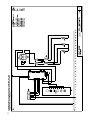
ELECTRICAL DATA:
Are to be found on the name plate inside
the appliance after removal of the filter
frame.
WARNING – Avoid risk of electrical
shock – Before undertaking any repairs,
always disconnect the hood from the
electricity supply.
Length of the connecting cable: 51
1
/
8
”.
This hood corresponds to EC regulations
concerning RF interference suppression.
PRIOR TO INSTALLATION
Page is loading ...

9
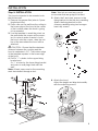
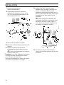
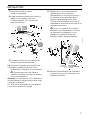
Step 5: INSTALLATION
This hood is intended to be mounted onto
the kitchen wall.
1. Remove the grease filter (refer to Opera-
ting Instructions).
2. Draw a line on the wall from the ceiling to
the lower edge of the hood at the center
of the location where the hood is going
to be mounted.
3. Use the template to mark the points on
the wall where the screws will be moun-
ted. In order to make it easier to hook
the hood onto the screws, draw the out-
line of the area where the hood will be
attached.
CAUTION – Ensure that the minimum
distance between the cooktop and the
hood is maintained – 30”. The bottom edge
of the template equates to the lower edge
of the hood.
4. Drill 2x
1
/
4
” ø holes for the upper fixing
bracket and
2x
1
/
4
” ø holes for the lower fixing bracket
and press in wall plugs flush with the
wall.
Note: At least one screw for the mounting
must be installed through a stud.
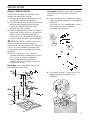
INSTALLATION
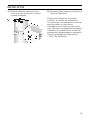
6. Attach the hood.
Adjust the height and align horizontally
with the adjusting screws.
Note: Take into account any special
accessories that are going to be fitted.
5. Attach the 2 enclosed spacers to the
fixing bracket for the flue duct panelling.
Attach the fixing bracket for the
chimney panelling using two hexagon
head cap screws.

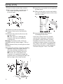
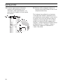
13. Insert the cover panels at an angle and
tilt them back.
14. Slide out the upper section and attach
it to the mounting brackets at the sides
with two screws.
15. Insert the grease filter (refer to
Operating Instructions).
If the vent system does not operate
satisfactorily during any of the above
procedures, review all steps in these
Installation Instructions to ensure that
nothing has been omitted or overlooked.
Also, refer to the Care & Use Manual for
additional information or call Thermador
Customer Support 1-800-735-4328.
07. Screw in lower screws (hex screws).
08. Stick protective film over the holes of
the 2 lower mounting bolts in the
protective grid.
1.
2.
1.
2.
3.
09. Connect up the air outlet pipe.
10. Connect the hood to the electricity
supply.
11. Remove the protective film from the
two flue ducts.
Take care not to damage the
surfaces which are susceptible to
scratches etc.
Warning: The interior walls of the flue
panelling can have sharp edges – Risk of
injury –.
We recommend that you wear gloves when
installing.
12. Push both sections of the flue panelling
together (slots in the upper section
must be pointing downwards) and
insert into the opening in the hood.
Protect the cover panels from
scratches, for example by laying the
template used for marking the wall over
the top edge of the lower section.
INSTALLATION
10
Page is loading ...
Page is loading ...
Page is loading ...
Page is loading ...
Page is loading ...
Page is loading ...
Page is loading ...
Page is loading ...
Page is loading ...
Page is loading ...
Page is loading ...
Page is loading ...
Page is loading ...
Page is loading ...
Page is loading ...
Page is loading ...
Page is loading ...
Page is loading ...
Page is loading ...
Page is loading ...
Page is loading ...

9000 333 896
Printed in Germany 0208 Es.
5551 McFadden Avenue, Huntington Beach, CA 92649 • 1-800-735-4328 • www.thermador.com
9000333896 • 10013 Rev B • 02/08 © BSH Home Appliances Corporation • Litho U.S.A.
-
 1
1
-
 2
2
-
 3
3
-
 4
4
-
 5
5
-
 6
6
-
 7
7
-
 8
8
-
 9
9
-
 10
10
-
 11
11
-
 12
12
-
 13
13
-
 14
14
-
 15
15
-
 16
16
-
 17
17
-
 18
18
-
 19
19
-
 20
20
-
 21
21
-
 22
22
-
 23
23
-
 24
24
-
 25
25
-
 26
26
-
 27
27
-
 28
28
-
 29
29
-
 30
30
-
 31
31
-
 32
32


Thermador HMCN36FS User manual
- Type
- User manual
- This manual is also suitable for
Ask a question and I''ll find the answer in the document
Finding information in a document is now easier with AI
in other languages
- français: Thermador HMCN36FS Manuel utilisateur
- español: Thermador HMCN36FS Manual de usuario
Related papers
-
Thermador HMIB40HS Installation guide
-
-
-
Thermador HDDW36DS Operating instructions
-
Thermador HPIN48HS Installation guide
-
Thermador DHG6023UC User manual
-
Thermador DHG6023UC Installation guide
-
-
-
Other documents
-
-
Bosch DKE9305AUC/02 Operating instructions
-
-
BALAY 3BD697X/02 User manual
-
Bosch DKE745K/01 User manual
-
-
-
-
Siemens LC 47955 User manual
-