NAMRON 4512738 User manual

Type
User manual

This manual is also suitable for

NAMRON 4512738 is a ZigBee-enabled thermostat that offers precise temperature control, scheduling, and energy-saving features for your home or office. With its intuitive interface and compatibility with various heating systems, it's a great choice for automating and optimizing your indoor climate.

NAMRON 4512738 is a ZigBee-enabled thermostat that offers precise temperature control, scheduling, and energy-saving features for your home or office. With its intuitive interface and compatibility with various heating systems, it's a great choice for automating and optimizing your indoor climate.

NAMRON THERMOSTAT
TOUCH ZIGBEE 16A
INSTRUCTION MANUAL
Namron termostat touch ZigBee 16A
INSTRUCTION MANUAL
Technical data
ZigBee Frequency
Operation voltage
Maximum load
Power consumption
Floor sensors supported
Control modes
2.4GHz
220-240V~50/60Hz
16A
Ambient temperature 0°C to 40°C (during operation)
<2W
Temperature range 0°C to 40°C
Hysteresis 0.5°C to 2°C (default 0.5°C)
IP rating
Relative humidity 8% to 80%
IP21
Control types Room sensor (factory default)
Floor sensor
Room + floor sensor
This parameter can also be configured through advance config parameter 10
1. Away 2. Auto 3. Manual 4. Drying 5. Off
Standard EN 60730-1:2016;A1, EN IEC 60730-2-9:2019;A1
EN IEC 61000-3-2:2019, EN 61000-3-3:2013+A1:2019,
EN 60730-1:2016+A1:2019,
EN 60730-2-19:2019+A1:2019+A2:2020,
EN 50663:2017;ETSI EN 301 489-1V2.2.3,
ETSI EN301 489-3V2.1.1 ETSI EN300 220-1 v3.1.1.,
ETSI EN300 220-2 V3.2.1
RED:2014/53/EU
Certificate ZigBee 3.0, CE, RED
NTC R25=10K±1%@25°C, B25/50=3950K±1% (factory setting)
NTC R25=15K±1%@25°C, B25/50=3950K±1%
NTC R25=12K±1%@25°C B25/50=3950K±1%
NTC R25=50K±1%@25°C, B25/50=3950K±1%
NTC R25=100K±1%@25°C, B25/50=3950K±1%
Floor sensor NTC R25=10K±1%@25°C, B25/50=3950K±1%, (3m included)
81mm
81mm
21.3mm28.4mm
Symbol overview
Installation
a.Installation must be done by a qualified electrician.
b.Power supply must be turned off during installation.
Remove the display unit and front cover by using a small screwdriver.
Insert the wires to the correct terminals as presented in the wiring diagram above. Suggested
wire-stripping length is 8-10mm.
Fix the thermostat into the connection box by tightening the screws. Make sure that the thermostat is
fixed without deformation. Suggested torque is 0.2-0.4Nm (2.0-4.1kgf.cm).
NTC L L N N
LN
Floor temp
sensor
4512737
(1) Wiring diagram
(2) Mounting
a.
b.
c.
Preview interface
Standby Interface
On Home Interface, user can enter into PREVIEW interface, the interface will display some basic configurations, energy
consumption, date, floor temperature etc.
Short press button to select the item would like to modify, then short press move up
and move down buttons to modify value of selected item, then short press button
to save and quit, short pressing button only quits without saving.
The device Time Cluster is client, if the bound device supports local time of Time Cluster, the device will acquire local
time from the bound device spontaneously under 3 situations: acquire after this device is added to a network, acquire
when the device already added to a network and power is reset, acquire every 24 hours .
How to enter settings menu:
1. Under Home Interface, meanwhile the device is at OFF mode , press and hold up and down buttons at the
same time for over 5 seconds to enter Settings Menu.
2. Short press move up and down button to select a settings item, then short press button F to enter selected item.
3. Settings menu include, Preview menu, Zigbee settings, Schedule, Monitor settings, Time/Date settings, Other settings.
User can set time to leave home and time to go home according to the requirements of themselves, and set how the
device will control the temperature during this period.
1.If away mode has already been activated, the end time for away mode is valid, the device will execute Away Mode
Temperature Schedule before the end time.
2.If away mode has already been activated, the values of end time for away mode are set as 0, the device will always
execute current set temperature with no time limitation. The device will consider the mode as antifreeze mode, the
recommended temperature setting is 4-10 , and factory default setting is 6 .
Short press button on Home Interface to switch operation modes: the icons of Away, Auto, Manual, Drying, Off modes
will be displayed alternatively for 3 seconds and last displayed mode will be selected, or just short press F button to select
a desired mode when the modes’ icon displayed alternatively. Press and hold button on Home interface for over 3
seconds to select Away mode directly, then Press and hold button for 3 seconds to quit Away mode.
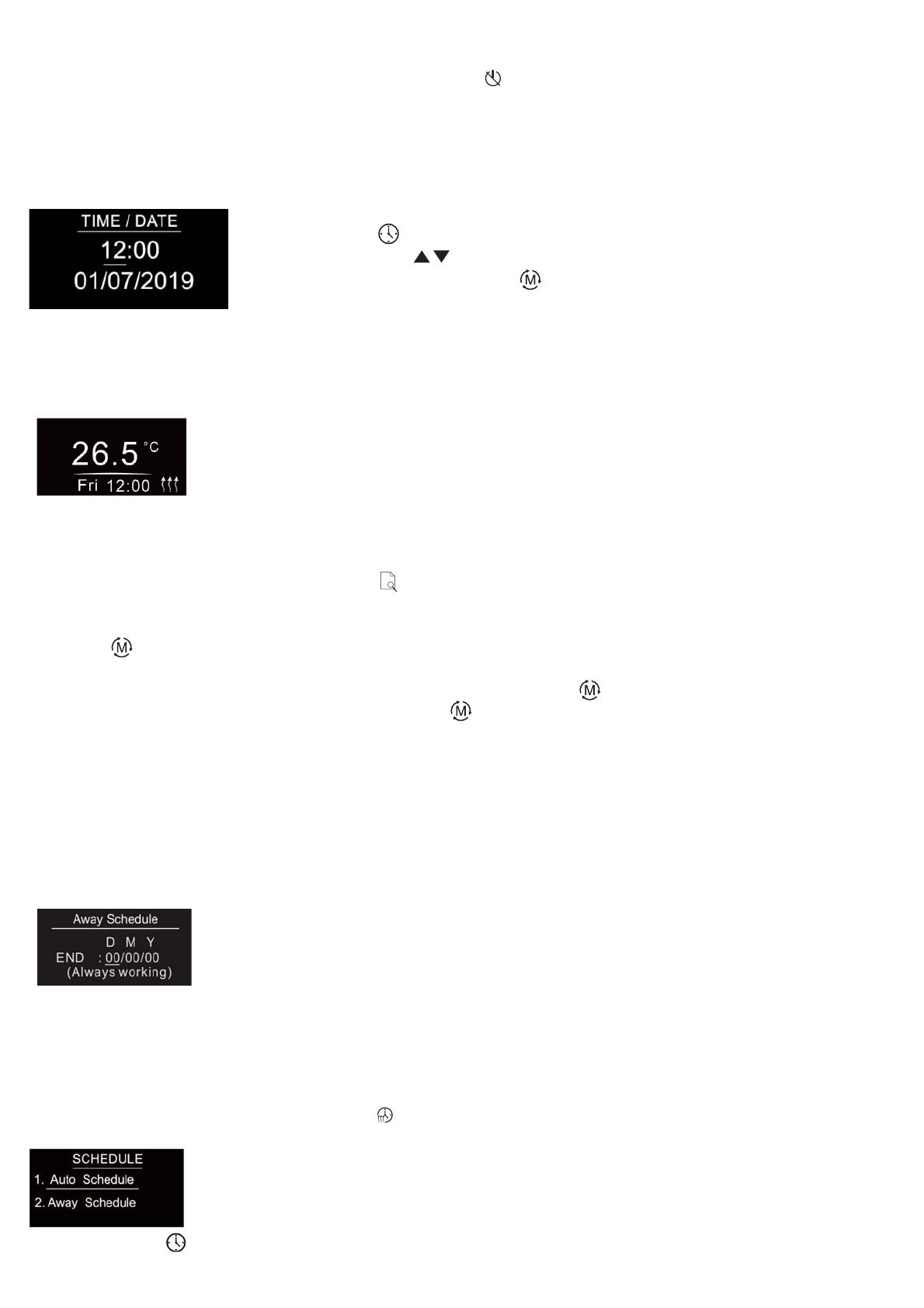
1.Away Mode Schedule
Time Setting
Settings Menu
Select TIME/DATE on Home Interface to enter into TIME/DATE SET interface as follow:
Control Mode
F
When Auto Mode Schedule is valid, the device will control according to the set temperature of the schedule. For
instance, if user would like to keep room temperature at 18 degree Celsius during 18:00-23:00 on every Monday, and
keep room temperature at 20 degree Celsius after 22:30 on every Monday, then user can set schedule by himself.
Schedule setting method 1: user can enters into schedule on System Setting Interface, the schedule interface is as
follows:
Short press button to select “Auto Schedule”, then short press button to enter into Auto Mode Schedule
weekly setting interface.
2. Auto Mode Schedule
F
If the device operation mode is set to any other mode except OFF Mode, and there is no
operation within 2 minutes, the device will go to this standby interface.
Once the device goes to standby interface, if Display Auto Off function is enabled and there is
no operation within 30 seconds, the display will go off automatically.
If the device operation mode is set to OFF Mode, and there is no operation within 2 minutes, the
display will go off automatically.
D means date, M means month, Y means year (2019-2099).
Start and end mean away time.
To enter into the setting interface and setting method, please refer to the 1.4
Auto Mode (Energy Save Mode) Schedule.
The function of monitor set is real time monitor of over current, over
heat and freezing. On Home Interface, short press MONITOR
SET to enter into monitor set interface a s follows:
Short press button to select the item would like to modify, then
short press move up and down buttons to modify value of selected
item, then short press button to save and quit, short pressing
button only quits without saving.
Monitor Set
F
Schedule setting method 2: on System Setting Interface, meanwhile the device is under Auto Mode , short press
button to enter into Auto Mode Schedule weekly setting interface quickly:
On Auto Mode Schedule weekly setting interface, use buttons and to enter into schedule setting of a certain
week as follows:
F
For each schedule, the latter time should be later than the former time, otherwise saving will fail with the error remind
“Time setting error!!!”. The default time schedules are as follows:
For example, in order to quickly dry the water on the floor of the bathroom, the device can be set to quickly heat in a
short time to dry the floor. Enter the configuration interface as follows:
Duration: set how long the dry mode lasts, can be configured through the proprietary attribute DryTime (0x1006) of
Thermostat Cluster (0x0201), the configurable range is 5-100 minutes.
After Mode: set the mode after the drying mode ends, can be configured through the proprietary attribute ModeAfter-
Dry (0x1007) of Thermostat Cluster (0x0201).
Remain: shows the remaining time of the drying mode
For configuration method and modification, please refer to Automatic Mode (Energy Save
Mode) Schedule:
3. Manual Mode: the device will control the heating system according to current set temperature. The temperature can be
set by move up and move down button on the Home interface, or configured by Zigbee gateway.
4. Dry Mode Schedule
Once the device is powered on and stable, referring to the room temperature sensor, if the temperature
decreases to the threshold of this setting, the window open mark will be enabled, the relay will be forced to turn
off to save energy, then the icon will appear.
After window open mark is enabled, if the temperature increases to the threshold of this setting in 3 minutes, the
window open mark will be disabled.
Once the window open mark is enabled, it will be disabled after 10 minutes, and the device will keep current working
mode.
This value can also be configured through the proprietary attribute WindowOpenCheck (0x1009) of Thermostat
Cluster (0x0201), 0 means this function is disabled.
Note: this function will work better when the device is installed beside the window or door.
Window Open Detect (disabled by default)
5.Off Mode
This mode means that the device is under idle status.
Monday-Friday 7:30,24C-12:00,20C
18:00,16C-22:30,18C
Saturday-Sunday 7:30,24C-12:00,20C
18:00,18C-22:30,18C
On Auto Day Schedule interface, short press button to select the time or temperature that
you would like to modify, then short press move up and move down buttons to modify
value, then short press button to save and quit, short pressing button only quits without
saving.
F
If current is over the set value, the relay will be forced to off by the
device, and the state will be reported to the gateway. The over
current alarm function can be disabled, which can be set directly
through the device. Or can be configured through the
ACAlarmsMask and ACCurrentOverload of Electrical Measurement
(0X0B04), for details please refer to the configuration value .
Note: When over current alarm is triggered, the beeper will beep,
to cancel the alarm, just press and hold button for over 3
seconds or reset power of the device. After cancel manually, the
relay will show heating forbidden icon within 120 seconds, but
other operations are allowed.
This function is similar to the function of “Internal Over Heat
Protection” described in chapter 4.9. When the control type is
configured as “Room+Floor sensor”, this function will be valid:
The alarm will be triggered when the floor sensor temperature >
Max floor temp, the relay will be forced to off by the device, and
the state will be reported to the gateway. The following indication
figure will prompt on the display.
After the floor sensor temperature < (Max floor temp - Hysteresis),
the alarm will be cancelled automatically and the device will restore
to previous operation mode.
To cancel the alarm manually, just press and hold button for
over 3 seconds, but the relay will show heating forbidden icon
within 120 seconds and the alarm will not be triggered again, after
120 seconds expire, the device will restore to previous operation
mode and continue to detect alarm temperature.
This function can be disabled, which can be configured directly
through the device, or can be configured through the attribute Max
floor temp (0x2001) of Thermostat Cluster (0x0201), when this value
is set as 0, this function is disabled.
To prevent the undulation of sensor temperature when the sensor
temperature is approaching the set temperature, which will cause
that the controller may keep switching on/off the relay. Here
hysterersis enables the controller to control the relay only when the
sensor temperature is lower than the set temperature minus the
hysteresis value , this value can be set.
For instance, when hysterersis is set as 0.5 degree, then only when
current sensor temperature < (the set temperature - 0.5 degree),
will the controller heat.
This value can also be configured through the proprietary attribute
Hysterersis (0x100A) of Thermostat Cluster (0x0201).
Over-current
Alarm
Set the level of vibration sensor under the buttons or buzzer level.
OFF: vibration or buzzer off Low Level, High Level: low vibration or
buzzer level, high vibration or buzzer level.
This level can also be configured through the proprietary attribute
ButtonVibrationLevel (0x1001) of Thermostat Cluster (0x0201).
Max floor temp
Hysterersis
Key Vibration
Set
The OLED display brightness when operate the device.
High Level, Mid Level, Low Level.
This brightness can also be configured through the proprietary
attribute OperateDisplayLcdBrightness (0x1000) of Thermostat
Cluster (0x0201).
Display
Brightness Set
16A by default
27°C by default
0.5°C by default
OFF by default
Mid Level by default
On the Home Interface, press and hold both and buttons for
over 10S, during the process, the icon will flash slowly, the
Display Auto OFF function can be enabled or disabled, when the
function is enabled, the icon will be displayed, otherwise the
icon will not be displayed.
This Display Auto Off can also be configured through the propri-
etary attribute 0x100B of Thermostat Cluster (0x0201).
On the Home Interface, press and hold both and buttons for
over 10S, the Child Lock can be enabled or disabled, when the
Child Lock is enabled, the icon will appear at the upper right
corner, otherwise the icon will not appear.
This Child Lock can also be configured through the attribute
KeypadLockout (0x0001) of Thermostat Cluster (0x0201).
Select OTHER SET on Home Interface to enter into OTHER SET
interface as follow:
Short press button to select the item you would like to modify,
then short press move up and down buttons to modify value of
selected item, then short press button to save and quit, short
pressing button only quits without saving.
The displayed temperature may has big tolerance caused by the
sensor or other factors, so it is necessary to do
temp compensation to room sensor and floor sensor.
Compensation range is -5 ~ +5°C, stepping is 0.5°C.
This value can also be configured through the attribute Local
TemperatureCalibration (0x0010) of Thermostat Cluster (0x0201),
and through the proprietary attribute FloorSensorCalibration
(0x1005) of Thermostat Cluster (0x0201).
Other Set
Temperature
Compensation 0 by default
last status by
default
Home Temp by
default
Device state after reset power of the device.
If set as “last status”, device will go to the status before power failure
after power on again.
If set as “default”, device will go to default mode after power on
again.
This status can also be configured through the proprietary attribute
PowerUpStatus (0x1004) of Thermostat Cluster (0x0201).
Re-power
Status
To ensure the safety of the device, if the internal temperature of the
device (not displayed on the interface) is over a certain value during
heating process, the device will execute a short temporary action to
turn off the relay, and the icon will appear on the interface, after
the temperature decreases to a certain value, the device will recover
to work.
Internal Over
Heat Protection
F
Child Lock
This parameter defines which sensor temperature will be displayed
on Home page.
Floor Temp: floor temperature (external sensor) .
Home Temp: indoor air temperature.
This status can also be configured through the proprietary attribute
TemperatureDisplay (0x1008) of Thermostat Cluster (0x0201).
Display
Temperature Set
Display
Auto Off
F
F
Adding to a Zigbee Network
F
Zigbee Configuration Introduction
Select Network Set on Home Interface to enter into Zigbee network management interface as follow:
Zigbee Interface
The thermostat provides 3 zigbee application endpoints:
Operate your Zigbee gateway to add device, select “Add”, then short press button , the device will search network
and try to join, “Status” will show “Inclusion...”. If there is no response from a gateway, or adding failed, “Status” will
show “Fail”. If added successfully, “Status” will show “Inclusion OK” and device ID.
Removing from a Zigbee Network
Operate your Zigbee gateway to remove device, Select “Remove”, then short press button , the device will send out
removing request, “Status” will show “Exclusion...”. If there is no response from a gateway, or removing failed, “Status”
will show “Fail”. If removed successfully, “Status” will show “Exclusion OK” and device ID will be showed as 0.
The device will be removed from the network and all parameters will be restored to factory default setting, all
bindings will be cleared.
Factory Reset (Reset)
Factory resetting will remove the device from Zigbee network and all parameters will be restored to factory default
setting, all bindings will be cleared.
Select “Reset”, then short press button , the device will start reset, “Status” will show “Reset...”. If exclusion failed,
“Status” will show “Fail”. If reset successfully, “Status” will show “Reset OK”.
F
F
Configure Device Operation Mode through Zigbee
5.1 Application Endpoint #0 –ZigBee Device Object
• Application profile Id 0x0000
• Application device Id 0x0000
• Supports all mandatory clusters
Since Zigbee does not have away mode, the attribute Occupancy (occupied or unoccupied) of Thermostat (0x0201)
and attribute Occupancy of received OccupancySensing (0x0406) are required to judge whether it is away mode.
1) if the device receives other devices’ or the gateway’s report: the Bit 0 of the value of attribute Occupancy (0x0000) of
OccupancySensing Cluster (0x0406) is 1, which means occupied, then the operation mode of the thermostat, the
attribute SystemMode(0x001c)=0x04(heat) of Thermostat (0x0201), meanwhile the value of attribute Occupancy
(0x0002) of Thermostat (0x0201) is 0. It means the Away Mode is activated, and the thermostat UI will display.
2) if the gateway send command to modify the attribute SystemMode(0x001c) of Thermostat (0x0201), the thermostat
will quit Away Mode. Meanwhile the value of attribute Occupancy (0x0002) of Thermostat (0x0201) is 1.
3) The proprietary attribute 0x2002(Manufacturer Code=0x1224) of the cluster 0x0201 can be modified to configure
whether it is away mode or at home.
Note: Away Mode uses attribute UnOccupiedHeatingSetpoint to set temperature.
Other modes uses attribute OccupiedHeatingSetpoint to set temperature.
Endpoint Profile Application
1(0x01)
0(0x00)
242(0xF2)
2(0x02) 0xA1E0(GP)
0x0104(HA)
0x0104(HA)
0x0000(ZDP) ZigBee Device Object (ZDO) standard management features
Device ID is 0x0007(OTA).
Device ID is 0x0301(Thermostat ).
Device ID is 0x0021(GreenPower).
5.2 Application Endpoint #1 –Thermostat
Cluster supported Description
0x0000 server Provides basic information about the device, such as the manufacturer ID,
vendor and model name, stack profile, ZCL version, production date,
hardware revision etc. Allows a factory reset of attributes, without the device
leaving the network.
Basic
0x0003 server Allows to put the endpoint into identify mode. Useful for identifying/locating
devices and required for Finding & Binding.
Identify
0x0004 server
Groups
Allows adding this endpoint to one or more groups. Afterwards the endpoint
can be addressed using the group address. This is also a prerequisite for
scenes. You may also query group membership and delete group
associations.
0x0005 server
Scenes
Allows storing one or more scenes per group, where each scene consists of a
pre-set on/off state value. You may either store the current values as a
scene, or provide scene settings when adding a scene, or delete scenes.
0x0201 server Thermostat
0x0702 server Simple Meter
0x0b04 server Electrical Measurement
Measuring power, voltage, current
0x0002 INT8U ,
read-only StackVersion
0x0003 INT8U ,
read-only HWVersion
Hardware version 1
0x0004 string,
read-only ManufacturerName
“NAMRON AS”
0x0005 string,
read-only ModelIdentifier
“4512737 & 4512738”
0x0006 string,
read-only DateCode
NULL
0x0007 ENUM8,
read-only PowerSource
Device power supply, fixed value 0x01 Mains (single phase)
0x0001 INT8U ,
read-only ApplicationVersion
This is the firmware version number of the application
Attribute Type Description
0x0000 INT8U,
read-only 0x03
ZCLVersion
5.2.1 Basic -0x0000 (Server)
Attributes supported:
0x0406 client Occupancy Sensing
0x000a Server Time
0x0204 server Thermostat User Interface Configuration
0x0009 server Alarm
Device related alarm
0x0008 ENUM8,
read-only GenericDevice-Class
0XFF
0x0009 ENUM8,
read-only GenericDevice-Type
0XFF
0x000A octstr
read-only ProductCode
00
0x000B string,
read-only NULL
ProductURL
0x4000 string,
read-only 6.9.1.0_r4
Sw build id
Command supported:
Command Description
0x00 On receipt of this command, the device resets all the attributes of all its
clusters to their factory defaults. Note that networking functionality, bindings,
groups, or other persistent data are not affected by this command.
Reset to Factory Defaults Command
5.2.2 Scenes 0x0005 (Server)
Attributes supported:
Attribute Type Description
0x0000 int8u,
read-only
SceneCount
Holds the total number of scenes (across all groups) currently stored on the
device.
Command supported:
Command Description
0x00 Add Scene
Adds a scene with or without a scene field set
0x01 Returns the scene field set, name and transition times for a scene.
View Scene
0x02 Removes a scene from the scene table.
Remove Scene
0x03 Removes all scenes that belong to a particular group.
Remove All Scenes
0x0003 bool,
read-only
SceneValid
If true, the scene identified by CurrentGroup and CurrentScene is currently
active, i.e. all device attribute values match the values in the scene field set.
0x0004 bitmap8 ,
read-only NameSupport
0x0002 int16u,
read-only If the SceneValid attribute is true, this attribute, together with the
CurrentScene attribute,indicates the currently active scene.
CurrentGroup
0x0001 int8u,
read-only
CurrentScene
If the SceneValid attribute is true, this attribute, together with the
CurrentGroup attribute,indicates the currently active scene.
0x04 Stores the device’s current state as a scene or updates a previously stored
scene accordingly
Store Scene
0x05 Recall Scene
Reverts the device’s current state using the values from the previously
stored field set.
5.2.3 Groups-0x0004 (Server)
Attributes supported:
Attribute Type Description
0x0000 bitmap8,
read-only 0, not supported
NameSupport
Command supported:
Command Description
0x00 Adds the endpoint to a group.
Add Group
0x01 View Group
Determines whether the device belongs to a group and returns the group
name, if supported
0x03 Remove Group
Removes this endpoint from the specified group. Also removes all scenes
that refer to this group.
0x04 Remove All Groups
Removes this endpoint from all groups. Also removes all scenes that refer to
any of the existing groups.
0x05 Add Group if Identifying
Adds this endpoint to the group, if the endpoint is identifying.
0x0002 bitmap8 ,
read-only When this flag is set as 1, it means occupied, OccupiedHeatingSetpoint will be
used, otherwise UnoccupiedHeatingSetpoint will be used.
Occupancy
0x0010 Int8S ,
reportable
LocalTemperatureCalibration
Room temperature calibration, range is -30-30, the maximum resolution this
format allows 0.1°C. Default value: 0
0x0011 int16S ,
reportable OccupiedCoolingSetpoint
This system is not invalid.
0x0012 int16S ,
reportable
OccupiedHeatingSetpoint
Range is 0-4000,the maximum resolution this format allows is 0.01 ºC. Default
is 0xbb8(30.00ºC)
0x0014 int16S ,
reportable Range is 0-4000,the maximum resolution this format allows is 0.01 ºC.
Default is 0x258(6.00ºC)
UnoccupiedHeatingSetpoint
0x0001 int16S ,
read-only reportable OutdoorTemperature
This is floor temperature, the maximum resolution this format allows is 0.01 ºC.
0x0000 int16S ,
read-only reportable LocalTemperature Attribute
This is room temperature, the maximum resolution this format allows is 0.01 ºC.
Attributes supported:
5.2.4 Thermostat-0x0201(Server)
Attribute Type Description
0x001B Enum8,
reportable Set device supported operation type, here only supports Heating Only(0x02)
ControlSequenceOfOperation
0x0029 Map16,
read-only,
reportable Indicates the relay on/off status, here only supports bit0( Heat State)
HVAC relay state/ ThermostatRunningState
Proprietary Attributes:
Attribute Type Description
0x1000 ENUM8,
reportable
OLED brightness when operate the buttons:
OperateDisplayLcdBrightnesss
Value=2 : High Level
Value=0 : Low Level
Value=1 : Mid Level(default)
Manufacturer
code
0x1224
0x1001 ENUM8
reportable
ButtonVibrationLevel
Value=0 : off(default)
Value=1 : Low Level
Key beep volume & vibration level:
Value=2 : High Level
0x1224
0x1002 ENUM8
reportable
FloorSenserType
Value=5 : NTC 12K/25
Value=4 : NTC 100K/25
Value=3 : NTC 50K/25
Select external (Floor) sensor type:
Value=1 : NTC 10K/25 (Default)
Value=2 : NTC 15K/25
0x1224
0x1003 ENUM8
reportable
ControlType
Value=0 : Room sensor(Default)
Value=1 : floor sensor
Value=2 : Room+floor sensor
The referring sensor for heat control:
0x1224
0x1007 ENUM8
reportable
Value=3 : Away mode
Value=0 : OFF
Value=2 : Auto mode –schedule (default)
ModeAfterDry
The mode after Dry Mode:
Value=1 : Manual mode
0x1224
0x1008 ENUM8
reportable Value=1 : Floor Temp
Value=0 : Room Temp (Default)
TemperatureDisplay :
0x1224
0x1009 INT8U
reportable
WindowOpenCheck
The threshold to detect open window, range is 0.3-8, unit is
0.5ºC,
0 means disabled, default is 0
0x1224
0x1006 INT8U
reportable The duration of Dry Mode, range is 5-100, unit is min.
Default value is 5.
DryTime
0x1224
0x1005 INT8S,
reportable The temp compensation for the external (floor) sensor, range
is -30-30, unit is 0.1°C. default value 0
FloorSenserCalibration
0x1224
0x1004 ENUM8
reportable Value=0 : default mode
The mode after reset power of the device:
Value=1 : last status before power off (Default)
PowerUpStatus
0x1224
0x100A INT8U
reportable Hysterersis setting, range is 5-50, unit is 0.1ºC, default value is 5
Hysterersis
0x1224
0x2001 INT8U,
reportable
Max floor temp
Floor temperature over heating threshold, range is 0-35, unit is 1ºC,
0 means this function is disabled, default value is 27.
0x1224
Command supported:
Command Description
0x0000 Setpoint Raise/Lower
Increase or decrease the set temperature according to current mode, unit is
0.1ºC
5.2.5 Simple Meter-0x0702 (Server)
Attributes supported:
Attribute Type Description
0x0000 unsigned48 ,
read-only,
reportable Indicates the current amount of electrical energy delivered to the load.
CurrentSummationDelivered
0x0200 bitmap8 ,
read-only Status
Flags indicating current device status, always is 0x00
0x0300 enum8 ,
read-only UnitOfMeasure
The unit of metering data, this is always kWh(0x00)
0x0303 map8 ,
read-only The decimal point on the left and right sides of the data, this is always 0x00
SummationFormatting
0x2002 ENUM8
reportable Value=1: away
Value=0: not away (default)
Away Mode Set:
0x1224
0x100B ENUM8
reportable 0, disable Display Auto Off function
DisplayAutoOffEnable
1, enable Display Auto Off function
0x1224
0x0000 bitmap32 ,
read-only
MeasurementType
Indicates the physical entities that this devices is able to measure. Supports
only bit0: Active measurement (AC)
0x0505 int16U ,
read-only,
reportable
RMSVoltage
Single phase valid voltage, unit is V
0x0508 int16U ,
reportable,
read-only Single phase valid current, unit is A
RMSCurrent
0x050B int16S ,
reportable
read-only Single phase valid power, unit is W
ActivePower
0x0600 int16U,
read-only ACVoltageMultiplier
5.2.6 Electrical Measurement-0x0b04(Server)
Attributes supported:
Attribute Type Description
0x0306 bitmap8,
read-only Metering data type, this is always Electric Metering (0x00)
MeteringDeviceType
0x0601 int16U,
read-only
ACVoltageDivisor
Used together with above attributes, the real displayed voltage =
RMSVoltage* ACVoltageMultiplier
/ ACVoltageDivisor
0x0602 int16U,
read-only ACCurrentMultiplier
0x0604 int16U,
read-only ACPowerMultiplier
0x0603 int16U,
read-only
ACCurrentDivisor
/ ACCurrentDivisor
U
0x01
0x0605 int16U,
read-only
ACPowerDivisor
0x01
Used together with above attributes, the real displayed power = Active Power *
ACPowerMultiplie / ACPowerDivisor
sed together with above attributes, the real displayed current = RMSCurrent
* ACCurrentMultiplier
0x0800 int16U, Specifies which configurable alarms may be generated, only
Bit1: Current Overload is set, if set=0, then ACCurrentOverload=0, over
current will not be detected
ACAlarmsMask
0x0802 int16S ,
reportable
read-only
ACCurrentOverload
Alarms when the current is over a certain value, 0, 10-16, unit is A, for the
unit please refer to RMSCurrent, ACCurrentMultiplier, ACCurrent Divisor
Proprietary Attributes:
Attribute
0x0000
Type
Int8u,
reportable
Manufacturer code
0x1224
Description
OverCurrent
Over current value set by the user, range is 0, 10-16,
ACCurrentOverload will change spontaneously if this
value is modified.
5.2.7 Alarm-0x0009(Server)
The Alarm Server cluster can generate the following commands
Please set a valid value for ACAlarmsMask of Electrical Measurement.
The Time cluster is a general cluster for time it is based on a UTC time in seconds since 0 hrs 0 mins 0 sec on
1st January 2000. Refer to [Z2] for ZigBee specification of the time cluster.
If the device has bound TIME cluster, then the device will acquire the value of Local Time (0x0007)
spontaneously.
5.2.8 Time-0x000A(server)
The metering device will use this clusters as a client provided that a suitable Time Server is available on the
network (most likely on the Gateway/concentrator)
0x00 Room air temperature over heat, not alarm code
CmdID Description
CmdID Description
0x00 Alarm:
The alarm code of Electrical Measurement is 0,
Proprietary command, Manufacturer code=0x1224
5.2.9 OccupancySensing-0x0406(client)
The attributes that can be received:
Attribute Type Description
0x0000 bitmap8 , Bit 0 specifies the sensed occupancy as follows: 1 = occupied, 0 = unoccupied.
This flag bit will affect the Occupancy attribute of HVAC cluster, and the
operation mode.
Occupancy
5.3 Application Endpoint #2–OTA
Cluster supported Description
0x0000 server Basic
0x0003 server Identify
0x0019 Client
OTA Upgrade
Pull-oriented firmware upgrade. Searches the network for mating servers and
allows the server to control all stages of the upgrade process, including which
image to download, when to download, at what rate and when to install the
downloaded image.
Ota complies to standard Zigbee protocol.
5.2.10 Thermostat User Interface Configuration-0x0204(Server)
Attributes supported:
Attribute Type Description
0x0000 Enum8,
reportable TemperatureDisplayMode
0x00 Temperature in , only support
0x0001 Enum8,
reportable
KeypadLockout
0x00 No Lockout
0x01 - 0x05 lockout
Namron AS
Nedre kalbakkvei 88B
1081 Oslo
Norway
  • Page 1 1
  • Page 2 2
  • Page 3 3
  • Page 4 4
  • Page 5 5
  • Page 6 6
  • Page 7 7
  • Page 8 8
  • Page 9 9
  • Page 10 10
  • Page 11 11
  • Page 12 12
  • Page 13 13
  • Page 14 14
  • Page 15 15
  • Page 16 16

NAMRON 4512738 User manual

Type
User manual
This manual is also suitable for

NAMRON 4512738 is a ZigBee-enabled thermostat that offers precise temperature control, scheduling, and energy-saving features for your home or office. With its intuitive interface and compatibility with various heating systems, it's a great choice for automating and optimizing your indoor climate.

Ask a question and I''ll find the answer in the document

Finding information in a document is now easier with AI