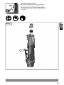
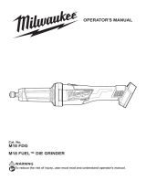
The Milwaukee M12FDGS is a compact and versatile tool suitable for grinding and cutting tasks. It features a powerful motor with three-speed settings, delivering up to 21,000rpm for efficient material removal. The tool's slim design and ergonomic handle ensure comfortable operation, while the LED light illuminates your work area for precise and controlled作業. With a collet diameter of 6.0mm and 8.0mm, the M12FDGS can accommodate a range of accessories, making it a versatile choice for various applications.
The Milwaukee M12FDGS is a compact and versatile tool suitable for grinding and cutting tasks. It features a powerful motor with three-speed settings, delivering up to 21,000rpm for efficient material removal. The tool's slim design and ergonomic handle ensure comfortable operation, while the LED light illuminates your work area for precise and controlled作業. With a collet diameter of 6.0mm and 8.0mm, the M12FDGS can accommodate a range of accessories, making it a versatile choice for various applications.


-
 1
1
-
 2
2
-
 3
3
-
 4
4
-
 5
5
-
 6
6
-
 7
7
-
 8
8
-
 9
9
-
 10
10
-
 11
11
-
 12
12
-
 13
13
-
 14
14
-
 15
15
-
 16
16


The Milwaukee M12FDGS is a compact and versatile tool suitable for grinding and cutting tasks. It features a powerful motor with three-speed settings, delivering up to 21,000rpm for efficient material removal. The tool's slim design and ergonomic handle ensure comfortable operation, while the LED light illuminates your work area for precise and controlled作業. With a collet diameter of 6.0mm and 8.0mm, the M12FDGS can accommodate a range of accessories, making it a versatile choice for various applications.
Ask a question and I''ll find the answer in the document
Finding information in a document is now easier with AI
Related papers
-
Milwaukee M18 FAP180 User manual
-
Milwaukee FSAG115XB User manual
-
Milwaukee M12 FCOT Installation guide
-
Milwaukee 6502508 User manual
-
Milwaukee C12 HZ User manual
-
Milwaukee 2409-20 User manual
-
Milwaukee M12 FDDX User manual
-
-
Milwaukee M18 BSX Operating instructions
-
Milwaukee M18 F2BL User manual
Other documents
-
Dremel 8250 Operating instructions
-
Arrow ROT3200K-A User manual
-
Ryobi PCL480B User manual
-
Bosch BOS-GRO12V35-06019C5070 Operating instructions
-
Ryobi RRT100 Owner's manual
-
-
 Milwaukee Tool M18FDG-0 User manual
-
Worx WX739 User manual
-
Makita GD0600 User manual
-
AEG WS 9-100 Original Instructions Manual
