Weller LR 82 Operating Instructions Manual
- Category
- Soldering irons
- Type
- Operating Instructions Manual

LR 82
Betriebsanleitung
Mode d’emploi
Gebruiksaanwijzing
Istruzioni per l’uso
Operating Instructions
Instruktionsbok
Manual de uso
Betjeningsvejledning
Manual do utilizador
Käyttöohjeet
√‰ËÁ›Â˜ §ÂÈÙÔ˘ÚÁ›·˜
Kullan∂m k∂lavuzu
Návod k pouÏití
Instrukcja obs∏ugi
Üzemeltetési utasítás
Návod na pouÏívanie
Navodila za uporabo
Kasutusjuhend
Naudojimo instrukcija
Lieto‰anas instrukcija

D
F
NL
I
GB
S
E
FIN
P
DK
Inhaltsverzeichnis Seite
1. Achtung! 1
2. Beschreibung 1
3. Inbetriebnahme 1
4. Arbeitshinweise 1
5. Fehleranalyse 1
6. Entfernen der Lötspitze 22
Table des matières Page
1. Attention! 2
2. Description 2
3. Mise en service 2
4. Instructions d’utilisation 2
5. Analyse des défauts 2
6.
Retrait de la panne
22
Inhoud Pagina
1. Attentie! 3
2. Beschrijving 3
3. Ingebruikname 3
4. Werkwijze 3
5. Foutanalyse 3
6.
Verwijderen van de soldeerpunt
22
Indice Pagina
1. Attenzione! 4
2. Descrizione 4
3. Messa in servicio 4
4. Indicazioni operative 4
5. Analisi guasti 4
6.
Rimozione della punta di brasatura 22
Table of contents Page
1. Caution! 5
2. Description 5
3. Commissioning 5
4. Note on use 5
5. Fault Finding 5
6.
Removing the Tip 22
Innehållsförteckning Sidan
1. Observera! 6
2. Beskrivning 6
3. Idrigttagning 6
4. Arbetsanvisningar 6
5. Felanalys 6
6.
Avlägsna lödspetsen
22
Indice Página
1. Atencion! 7
2. Descripción 7
3. Puesta en funcionamiento 7
4. Notas sobre la operación 7
5. Análisis de fallos 7
6.
Desmontaje de la punta para soldar
22
Indholdsfortegnelse side
1. Bemærk! 8
2. Beskrivelse 8
3. Ibrugtagning 8
4. Arbejdsanvisninger 8
5. Fejlsøgning 8
6.
Afmontering af loddespidser 22
7. Loddespidser, aflodningshoveder
Índice Página
1. Atenção! 9
2. Descrição 9
3. Colocação em funcionamento 9
4. Instruções de trabalho 9
5. Análise de erros 9
6.
Remoção da ponta de solda 22
Sisällysluettelo Sivu
1. Huomio! 10
2. Kuvaus 10
3. Käyttöönotto 10
4. Työohjeet 10
5. Virheanalyysi 10
6.
Juottokärjen poisto 22
Page is loading ...

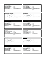
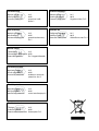
Dati tecnici
Tensione di alimentazione: 24 V
Potenza dello stilo: 80 Watt
Compensazione del potenziale:cavo di compensazione
pin 5
Teknik bilgiler
Besleme gerilimi: 24 V
Havya gücü: 80 W
Potansiyel dengelemesi: Dengeleme hatt∂ uç 5
Δ¯ÓÈο ÛÙÔȯ›·
Δ¿ÛË ÙÚÔÊÔ‰ÔÛ›·˜: 24 V
πÛ¯‡˜ ÂÌ‚fiÏÔ˘ Û˘ÁÎfiÏÏËÛ˘: 80 W
∂͛ۈÛË ‰˘Ó·ÌÈÎÔ‡: ∞ÁˆÁfi˜ Â͛ۈÛ˘ ·Î›‰· 5
Tekniset tiedot
Syöttöjännite: 24 V
Juottokärjen teho: 80 W
Potentiaalintasaus: tasausjohto Pin 5
Tekniske data
Forsyningsspænding: 24 V
Loddekolbeeffekt: 80 W
Potentialudligning: udligningsledning Pin 5
Caractéristiques techniques
Tension d’alimentation: 24 V
Puissance du fer à souder: 80 W
Compensation du potentiel: câble d’équipotentialité
broche 5
Technische gegevens
Netspanning: 24 V
Soldeerboutvermogen: 80 W
Equipotentiaal: compensatieleiding pin 5
Datos técnicos
Tensión alimentada: 24 V
Potencia del soldador: 80 W
Compensación de potencial: línea de compensación,
pin 5
Technical Data
Supply Voltage: 24 V
Soldering Iron Power Rating: 80 W
Potential Equalisation: Equalisation Lead - Pin 5
Technische Daten
Versorgungsspannung: 24 V
Lötkolbenleistung: 80 W
Potentialausgleich: Ausgleichsleitung Pin 5
Dados técnicos
Tensão de alimentação: 24 V
Potência do ferro de soldar: 80 W
Compensação de potência: Cabo de compensação
Pin 5
Tekniska data
Försörjningsspänning: 24 V
Lödkolvskapacitet: 80 W
Potentialutjämning: Utjämningsledning Pin 5
Page is loading ...
Page is loading ...
Page is loading ...
Page is loading ...
Page is loading ...

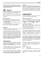
Thank you for placing your trust in our company by purchasing
the Weller soldering iron LR 82. Production was based on strin-
gent quality requirements which guarantee the perfect operation
of the device.
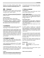
1. Caution!
Please read these Operating Instructions and the attached Safety
Information carefully prior to initial operation. Failure to observe
the safety regulations results in a risk to life and limb.
The manufacturer shall not be liable for damage resulting from
misuse of the machine or unauthorised alterations.
Safety Informations
● Always place the soldering iron in the original holder.
● Remove all inflammable objects from the proximity of the
hot soldering tool.
● Use suitable protective clothing. Risk of burns from liquid
solder.
● Never leave the hot soldering iron unsupervised.
● Never work on voltage-carrying parts.
2. Description
The LR 82 soldering iron is of use wherever large amounts of
energy with precise temperature control are required.
The HT long life tips are heated from the inside and are fixed to
the 80 Watt low voltage element with a bayonet connector that
prevents the tip turning. The 80 Watt heater power combined
with the optimal transfer of heat to the soldering iron tip guaran-
tee the high performance capability of the soldering iron. Using
an integrated equipotential bonding wire, it is possible to equi-
potentially bond the soldering iron tip as required. The anti-sta-
tic design of the handle and cable comply with the requirements
for electrostatic sensitive device safety.
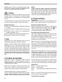
3. Commissioning
Place the soldering iron in the safety stand. Insert the soldering
iron plug in the socket on the power supply unit and lock. Switch
on the power supply unit and set to the desired temperature.
As standard, the soldering iron is equipped with an HT 2 (5 mm)
tip. Various shapes and widths of bit are available. Choose the
one best suited to your requirements from the range.
The temperature is set in a range between 50 °C (150 °C) and
450 °C. A blinking LED in the display signals that the preset tem-
perature has been reached – this serves as a optical regulator.
Constant illumination means that the system is overheating.
Maintenance
The sensor and heater element are built into a corrosion resi-
stant stainless steel body. To ensure optimal heat transfer, this
body has a conically shaped tip that fits snugly in the soldering
iron tip. Please ensure that this joint is not degraded by dirt,
foreign bodies, or damage since this would have an effect on the
precision of the temperature regulation.
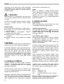
4. Notes on Use
Tip Changing
The method of fixing the tip to the LR 82 enables tips to be chan-
ged rapidly and ensures their accurate positioning without the
need to undo the tip sleeve.
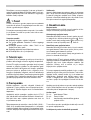
Removing the Tip
Position 10 AF open ended spanner and ensure correctly sea
ted. Press the tip axially to the stop . Turn the tip clockwise
to the stop and remove to the front. (Page 22)
Fitting the New Tip
Put the open ended spanner on the cold tip, then place on the
heater element. Pay attention to correct positioning.
1.Press the tip into the sprung heater element to the stop
2.Turn the tip anticlockwise to the stop and remove the open
ended spanner.
HT soldering iron tips are long life tips, i.e. the life of the tips is
considerably increased by galvanically coating the copper core
with corrosion resistant material. Any form of mechanical re-
finishing of the tip, including abrasive cleaning, will destroy this
protective layer and reduce the life of the tip.
When heating up the selectively tinned tips for the first time, wet
the tip with solder. This will remove oxide layers that have built
up on the tip in storage. Always ensure that the soldering iron is
placed in the safety stand with a well tinned tip before long
breaks between use. Do not use corrosive cleaners or fluxes.
The soldering station used has been set up for a medium size tip.
Variations in temperature can result from changing the tip or the
usage of other tip shapes.
Fault Finding
Pin 1-2: Heater Element 7 Ohm
Pin 3-4: Sensor 21 Ohm
Pin 5: Potential Equalisation 0 Ohm to the Soldering
Iron Tip
The operating instructions for the power supply unit used are
applicable in addition to these operating instructions
Subject to technical change without notice!
1
English
5
3
2
Page is loading ...
Page is loading ...
Page is loading ...
Page is loading ...
Page is loading ...
Page is loading ...
Page is loading ...
Page is loading ...
Page is loading ...
Page is loading ...
Page is loading ...
Page is loading ...
Page is loading ...
Page is loading ...
Page is loading ...
Page is loading ...
Page is loading ...

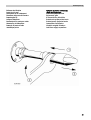
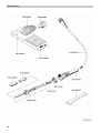
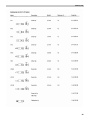
Exploded Drawing
23
Page is loading ...

www.weller.eu
005 56 573 03 / 01.08 Copyright by Cooper Tools GmbH, Germany
Cooper Tools GmbH
Carl-Benz-Str. 2
74354 Besigheim
Germany
Tel.: (07143) 580-0
Fax: (07143) 580-108
Cooper Tools S.A.S.
25 Rue Maurice Chevalier BP 46
77832 Ozoir-la-Ferrière Cedex
France
Tél.: (01) 60 18 55 40
Fax: (01) 64 40 33 05
Cooper Tools
A Division of Cooper
(Great Britain) Limited
4th Floor Pennine House
Washington
Tyne & Wear
NE37 1LY
Great Britain
Tel.: (0191) 419 7700
Fax: (0191) 417 9421
Cooper Italia S.r.I.
Viale Europa 80
20090 Cusago (MI)
Italy
Tel.: (02) 90 33 101
Fax: (02) 90 39 42 31
Erem S.A.
Rue de la Roselière
1400 Yverdon les Bain
Tel: (024) 426 12 06
Fax: (024) 425 09 77
Cooper Tools
P.O. Box 728
Apex, NC 27502-0728
Northeast
Phone: 919-362-7540
Fax: 800-854-5137
South
Phone: 919-362-7541
Fax: 800-854-5139
Midwest
Phone: 919-362-7542
Fax: 800-854-5138
West Coast (Southwest)
Phone: 919-362-1709
Fax: 800-546-7312
All other USA inquires
Fax: 800-423-6175
Weller
®
is a registered Trademark and registered Design of Cooper Industries Inc.
-
 1
1
-
 2
2
-
 3
3
-
 4
4
-
 5
5
-
 6
6
-
 7
7
-
 8
8
-
 9
9
-
 10
10
-
 11
11
-
 12
12
-
 13
13
-
 14
14
-
 15
15
-
 16
16
-
 17
17
-
 18
18
-
 19
19
-
 20
20
-
 21
21
-
 22
22
-
 23
23
-
 24
24
-
 25
25
-
 26
26
-
 27
27
-
 28
28
-
 29
29
-
 30
30


Weller LR 82 Operating Instructions Manual
- Category
- Soldering irons
- Type
- Operating Instructions Manual
Ask a question and I''ll find the answer in the document
Finding information in a document is now easier with AI
in other languages
- italiano: Weller LR 82
- français: Weller LR 82
- español: Weller LR 82
- Deutsch: Weller LR 82
- Nederlands: Weller LR 82
- português: Weller LR 82
- slovenčina: Weller LR 82
- dansk: Weller LR 82
- polski: Weller LR 82
- čeština: Weller LR 82
- Türkçe: Weller LR 82
- svenska: Weller LR 82
- suomi: Weller LR 82
Related papers
-
Weller WP 120 Operating instructions
-
Weller WSP 80 Operating instructions
-
-
Weller WS 51 User manual
-
-
-
-
Weller WMRP Operating Instructions Manual
-
-

