Lincoln Electric Red-D-Arc FX450 Operating instructions
- Category
- Welding System
- Type
- Operating instructions

RED-D-ARC
FX450
IM10094
February, 2011
Red-D-Arc Spec-Built Welding Equipment
This
RED-D-ARC
welder is built to
RED-D-ARC Extreme Duty
design specifications by Lincoln Electric.
Safety Depends on You
This welder is designed and built with safety in mind.
However, your overall safety can be increased by proper installation
... and thoughtful operation on your part.
DO NOT INSTALL, OPERATE OR REPAIR THIS EQUIPMENT
WITHOUT READING THIS MANUAL AND THE SAFETY
PRECAUTIONS CONTAINED THROUGHOUT.
And, most importantly, think before you act and be careful.
For use with machines having Code Numbers:
11789
North America’s Largest Fleet of Welding Equipment
OPERATOR’S MANUAL
(

FOR ENGINE
powered equipment.
1.a. Turn the engine off before troubleshooting and maintenance
work unless the maintenance work requires it to be running.
____________________________________________________
1.b. Operate engines in open, well-ventilated
areas or vent the engine exhaust fumes
outdoors.
____________________________________________________
1.c. Do not add the fuel near an open flame
welding arc or when the engine is running.
Stop the engine and allow it to cool before
refueling to prevent spilled fuel from vaporiz-
ing on contact with hot engine parts and
igniting. Do not spill fuel when filling tank. If
fuel is spilled, wipe it up and do not start
engine until fumes have been eliminated.
____________________________________________________
1.d. Keep all equipment safety guards, covers and devices in
position and in good repair.Keep hands, hair, clothing and
tools away from V-belts, gears, fans and all other moving
parts when starting, operating or repairing equipment.
____________________________________________________
1.e. In some cases it may be necessary to remove safety
guards to perform required maintenance. Remove
guards only when necessary and replace them when the
maintenance requiring their removal is complete.
Always use the greatest care when working near moving
parts.
___________________________________________________
1.f. Do not put your hands near the engine fan.
Do not attempt to override the governor or
idler by pushing on the throttle control rods
while the engine is running.
___________________________________________________
1.g. To prevent accidentally starting gasoline engines while
turning the engine or welding generator during maintenance
work, disconnect the spark plug wires, distributor cap or
magneto wire as appropriate.
i
SAFETY
i
ARC WELDING CAN BE HAZARDOUS. PROTECT YOURSELF AND OTHERS FROM POSSIBLE SERIOUS INJURY OR DEATH.
KEEP CHILDREN AWAY. PACEMAKER WEARERS SHOULD CONSULT WITH THEIR DOCTOR BEFORE OPERATING.
Read and understand the following safety highlights. For additional safety information, it is strongly recommended that you
purchase a copy of “Safety in Welding & Cutting - ANSI Standard Z49.1” from the American Welding Society, P.O. Box
351040, Miami, Florida 33135 or CSA Standard W117.2-1974. A Free copy of “Arc Welding Safety” booklet E205 is available
from the Lincoln Electric Company, 22801 St. Clair Avenue, Cleveland, Ohio 44117-1199.
BE SURE THAT ALL INSTALLATION, OPERATION, MAINTENANCE AND REPAIR PROCEDURES ARE
PERFORMED ONLY BY QUALIFIED INDIVIDUALS.
WARNING
ELECTRIC AND
MAGNETIC FIELDS
may be dangerous
2.a. Electric current flowing through any conductor causes
localized Electric and Magnetic Fields (EMF). Welding
current creates EMF fields around welding cables and
welding machines
2.b. EMF fields may interfere with some pacemakers, and
welders having a pacemaker should consult their physician
before welding.
2.c. Exposure to EMF fields in welding may have other health
effects which are now not known.
2.d. All welders should use the following procedures in order to
minimize exposure to EMF fields from the welding circuit:
2.d.1.
Route the electrode and work cables together - Secure
them with tape when possible.
2.d.2. Never coil the electrode lead around your body.
2.d.3. Do not place your body between the electrode and
work cables. If the electrode cable is on your right
side, the work cable should also be on your right side.
2.d.4. Connect the work cable to the workpiece as close as
possible to the area being welded.
2.d.5. Do not work next to welding power source.
1.h. To avoid scalding, do not remove the
radiator pressure cap when the engine is
hot.
CALIFORNIA PROPOSITION 65 WARNINGS
Diesel engine exhaust and some of its constituents
are known to the State of California to cause can-
cer, birth defects, and other reproductive harm.
The engine exhaust from this product contains
chemicals known to the State of California to cause
cancer, birth defects, or other reproductive harm.
The Above For Diesel Engines
The Above For Gasoline Engines

ii
SAFETY
ii
ARC RAYS can burn.
4.a. Use a shield with the proper filter and cover
plates to protect your eyes from sparks and
the rays of the arc when welding or observing
open arc welding. Headshield and filter lens
should conform to ANSI Z87. I standards.
4.b. Use suitable clothing made from durable flame-resistant
material to protect your skin and that of your helpers from
the arc rays.
4.c. Protect other nearby personnel with suitable, non-flammable
screening and/or warn them not to watch the arc nor expose
themselves to the arc rays or to hot spatter or metal.
ELECTRIC SHOCK can
kill.
3.a. The electrode and work (or ground) circuits
are electrically “hot” when the welder is on.
Do not touch these “hot” parts with your bare
skin or wet clothing. Wear dry, hole-free
gloves to insulate hands.
3.b. Insulate yourself from work and ground using dry insulation.
Make certain the insulation is large enough to cover your full
area of physical contact with work and ground.
In addition to the normal safety precautions, if welding
must be performed under electrically hazardous
conditions (in damp locations or while wearing wet
clothing; on metal structures such as floors, gratings or
scaffolds; when in cramped positions such as sitting,
kneeling or lying, if there is a high risk of unavoidable or
accidental contact with the workpiece or ground) use
the following equipment:
• Semiautomatic DC Constant Voltage (Wire) Welder.
• DC Manual (Stick) Welder.
• AC Welder with Reduced Voltage Control.
3.c. In semiautomatic or automatic wire welding, the electrode,
electrode reel, welding head, nozzle or semiautomatic
welding gun are also electrically “hot”.
3.d. Always be sure the work cable makes a good electrical
connection with the metal being welded. The connection
should be as close as possible to the area being welded.
3.e. Ground the work or metal to be welded to a good electrical
(earth) ground.
3.f.
Maintain the electrode holder, work clamp, welding cable and
welding machine in good, safe operating condition. Replace
damaged insulation.
3.g. Never dip the electrode in water for cooling.
3.h. Never simultaneously touch electrically “hot” parts of
electrode holders connected to two welders because voltage
between the two can be the total of the open circuit voltage
of both welders.
3.i. When working above floor level, use a safety belt to protect
yourself from a fall should you get a shock.
3.j. Also see Items 6.c. and 8.
FUMES AND GASES
can be dangerous.
5.a. Welding may produce fumes and gases
hazardous to health. Avoid breathing these
fumes and gases. When welding, keep
your head out of the fume. Use enough
ventilation and/or exhaust at the arc to keep
fumes and gases away from the breathing zone. When
welding with electrodes which require special
ventilation such as stainless or hard facing (see
instructions on container or MSDS) or on lead or
cadmium plated steel and other metals or coatings
which produce highly toxic fumes, keep exposure as
low as possible and within applicable OSHA PEL and
ACGIH TLV limits using local exhaust or mechanical
ventilation. In confined spaces or in some circum-
stances, outdoors, a respirator may be required.
Additional precautions are also required when welding
on galvanized steel.
5. b. The operation of welding fume control equipment is affected
by various factors including proper use and positioning of
the equipment, maintenance of the equipment and the spe-
cific welding procedure and application involved. Worker
exposure level should be checked upon installation and
periodically thereafter to be certain it is within applicable
OSHA PEL and ACGIH TLV limits.
5.c.
Do not weld in locations near chlorinated hydrocarbon
vapors
coming from degreasing, cleaning or spraying operations.
The heat and rays of the arc can react with solvent vapors
to
form phosgene, a highly toxic gas, and other irritating prod-
ucts.
5.d. Shielding gases used for arc welding can displace air and
cause injury or death. Always use enough ventilation,
especially in confined areas, to insure breathing air is safe.
5.e. Read and understand the manufacturer’s instructions for this
equipment and the consumables to be used, including the
material safety data sheet (MSDS) and follow your
employer’s safety practices. MSDS forms are available from
your welding distributor or from the manufacturer.
5.f. Also see item 1.b.

iii
SAFETY
iii
FOR ELECTRICALLY
powered equipment.
8.a. Turn off input power using the disconnect
switch at the fuse box before working on
the equipment.
8.b. Install equipment in accordance with the U.S. National
Electrical Code, all local codes and the manufacturer’s
recommendations.
8.c. Ground the equipment in accordance with the U.S. National
Electrical Code and the manufacturer’s recommendations.
CYLINDER may explode
if damaged.
7.a. Use only compressed gas cylinders
containing the correct shielding gas for the
process used and properly operating
regulators designed for the gas and
pressure used. All hoses, fittings, etc. should be suitable for
the application and maintained in good condition.
7.b. Always keep cylinders in an upright position securely
chained to an undercarriage or fixed support.
7.c. Cylinders should be located:
• Away from areas where they may be struck or subjected to
physical damage.
• A safe distance from arc welding or cutting operations and
any other source of heat, sparks, or flame.
7.d. Never allow the electrode, electrode holder or any other
electrically “hot” parts to touch a cylinder.
7.e. Keep your head and face away from the cylinder valve outlet
when opening the cylinder valve.
7.f. Valve protection caps should always be in place and hand
tight except when the cylinder is in use or connected for
use.
7.g. Read and follow the instructions on compressed gas
cylinders, associated equipment, and CGA publication P-l,
“Precautions for Safe Handling of Compressed Gases in
Cylinders,” available from the Compressed Gas Association
1235 Jefferson Davis Highway, Arlington, VA 22202.
WELDING and CUTTING
SPARKS can
cause fire or explosion.
6.a.
Remove fire hazards from the welding area.
If this is not possible, cover them to prevent
the welding sparks from starting a fire.
Remember that welding sparks and hot
materials from welding can easily go through small cracks
and openings to adjacent areas. Avoid welding near
hydraulic lines. Have a fire extinguisher readily available.
6.b. Where compressed gases are to be used at the job site,
special precautions should be used to prevent hazardous
situations. Refer to “Safety in Welding and Cutting” (ANSI
Standard Z49.1) and the operating information for the
equipment being used.
6.c. When not welding, make certain no part of the electrode
circuit is touching the work or ground. Accidental contact
can cause overheating and create a fire hazard.
6.d. Do not heat, cut or weld tanks, drums or containers until the
proper steps have been taken to insure that such procedures
will not cause flammable or toxic vapors from substances
inside. They can cause an explosion even
though
they have
been “cleaned”. For information, purchase “Recommended
Safe Practices for the
Preparation
for Welding and Cutting of
Containers and Piping That Have Held Hazardous
Substances”, AWS F4.1 from the American Welding Society
(see address above).
6.e. Vent hollow castings or containers before heating, cutting or
welding. They may explode.
6.f.
Sparks and spatter are thrown from the welding arc. Wear oil
free protective garments such as leather gloves, heavy shirt,
cuffless trousers, high shoes and a cap over your hair. Wear
ear plugs when welding out of position or in confined places.
Always wear safety glasses with side shields when in a
welding area.
6.g. Connect the work cable to the work as close to the welding
area as practical. Work cables connected to the building
framework or other locations away from the welding area
increase the possibility of the welding current passing
through lifting chains, crane cables or other alternate cir-
cuits. This can create fire hazards or overheat lifting chains
or cables until they fail.
6.h. Also see item 1.c.
6.I. Read and follow NFPA 51B “ Standard for Fire Prevention
During Welding, Cutting and Other Hot Work”, available
from NFPA, 1 Batterymarch Park, PO box 9101, Quincy, Ma
022690-9101.
6.j. Do not use a welding power source for pipe thawing.
Refer to http://www.lincolnelectric.com/safety for additional safety information.
Page is loading ...

vv
Thank You
for selecting one of our QUALITY products. We want you to take
pride in operating this product ••• as much pride as we have in
bringing this product to you!
Read this Operators Manual completely before attempting to use this equipment. Save this manual and keep it
handy for quick reference. Pay particular attention to the safety instructions we have provided for your protection.
The level of seriousness to be applied to each is explained below:
WARNING
This statement appears where the information must be followed exactly to avoid serious personal injury or loss of life.
This statement appears where the information must be followed to avoid minor personal injury or damage to this equipment.
CAUTION
Please Examine Carton and Equipment For Damage Immediately
When this equipment is shipped, title passes to the purchaser upon receipt by the carrier. Consequently, Claims
for material damaged in shipment must be made by the purchaser against the transportation company at the
time the shipment is received.
Please record your equipment identification information below for future reference. This information can be
found on your machine nameplate.
Product _________________________________________________________________________________
Model Number ___________________________________________________________________________
Code Number or Date Code (if available)______________________________________________________
Serial Number (if available)__________________________________________________________________
Date Purchased___________________________________________________________________________
Where Purchased_________________________________________________________________________
Whenever you request replacement parts or information on this equipment, always supply the information you
have recorded above.
CUSTOMER ASSISTANCE POLICY
The business of our company is manufacturing and selling high quality welding equipment. Our challenge is to
meet the needs of our customers and to exceed their expectations. On occasion, purchasers may ask us for
advice or information about their use of our products. We respond to our customers based on the best informa-
tion in our possession at that time. We are not in a position to warrant or guarantee such advice, and assume no
liability, with respect to such information or advice. We expressly disclaim any warranty of any kind, including any
warranty of fitness for any customerʼs particular purpose, with respect to such information or advice. As a matter
of practical consideration, we also cannot assume any responsibility for updating or correcting any such informa-
tion or advice once it has been given, nor does the provision of information or advice create, expand or alter any
warranty with respect to the sale of our products.
We are a responsive manufacturer, but the selection and use of specific products sold by us is solely within the
control of, and remains the sole responsibility of the customer. Many variables beyond our control affect the
results obtained in applying these types of fabrication methods and service requirements.
Subject to Change – This information is accurate to the best of our knowledge at the time of printing.

vi vi
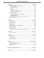
TABLE OF CONTENTS
Page
Installation .......................................................................................................Section A
Technical Specifications ........................................................................................A-1
Welding Process, Physical Dimensions ..........................................................A-2
Safety Precautions ..........................................................................................A-3
Select Suitable Location..................................................................................A-3
Lifting...............................................................................................................A-3
Stacking ..........................................................................................................A-3
Environmental Limitations ...............................................................................A-3
Input and Grounding Connections ..................................................................A-3
High Frequency Protection ....................................................................................A-3
Input Connection ............................................................................................A-4
Input Fuse and Supply Wire Considerations...................................................A-4
Input Voltage Selection ...................................................................................A-4
Cable Connections..........................................................................................A-5
Recommended Electrode and Work Cable for arc Welding ..................................A-6
Output Cable Guidelines........................................................................................A-6
________________________________________________________________________
Operation .........................................................................................................Section B
Safety Precautions ................................................................................................B-1
Graphic Symbols............................................................................................B-1, B-2
Product Description ..............................................................................................B-2
Duty Cycle .............................................................................................................B-2
Design Features ....................................................................................................B-2
Recommended Processes and Equipment ...........................................................B-3
Case Front Controls...............................................................................................B-4
Power-Up Sequence..............................................................................................B-5
Case Back Controls...............................................................................................B-5
Common Welding Procedures, Weld Controls and Displays..................B-5, thru B-8
_______________________________________________________________________
Accessories.....................................................................................................Section C
Options / Accessories............................................................................................C-1
________________________________________________________________________
Maintenance ....................................................................................................Section D
Safety Precautions ................................................................................................D-1
V
ISUAL INSPECTION...................................................................................................D-1
ROUTINE MAINTENANCE ............................................................................................D-1
PERIODIC MAINTENANCE ...........................................................................................D-1
________________________________________________________________________
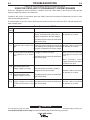
Section E ..............................................................................................Troubleshooting
Safety Precautions.................................................................................................E-1
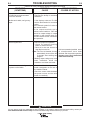
How to Use Troubleshooting Guide.......................................................................E-1
Troubleshooting Guide ..........................................................................................E-2
Error Codes ...........................................................................................................E-3
________________________________________________________________________
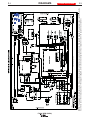
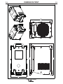
Wiring Diagram and Dimension Print ..............................................................Section F
________________________________________________________________________
Parts List .....................................................................................................P-678 Series
________________________________________________________________________

FX450 (RED-D-ARC)
A-1
INSTALLATION
A-1
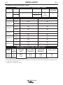
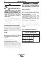
TECHNICAL SPECIFICATIONS -
FX450
RATED OUTPUT
POWER SOURCE-INPUT VOLTAGE AND CURRENT
Model
K3073-1
Duty Cycle
60% rating
100% rating
Volts at Rated Amperes
36.5V
34V
28V
26V
38V
36V
36.5V
34V
36.5V
34V
Amperes
450
400
450
400
450
400
450
400
450
400
Duty Cycle
60%
100%
60%
100%
60%
100%
60%
100%
60%
100%
Process
GMAW (CV)
GTAW (CC)
SMAW (CC)
FCAW-GS (CV)
FCAW-SS (CV)
Input Amperes
37 / 27 / 22
29 / 21 / 17
Idle Power
72 Watts
Max.
(fan on)
Power Factor @
Rated Output
95%
Input Voltage ± 10%
380 / 460 / 575 / 3 / 50 / 60
(1)
Cord and Fuse Sizes based upon the U.S. National Electric Code and maximum output for 40°C (104°) ambient.
(2)
Also called “inverse time” or “thermal/magnetic” circuit breakers; circuit breakers that have a delay in tripping action that decreases as the
magnitude of current increases.
(3)
Type SD cord or similar in 30°C ambient.
VOLTAGE
50/60Hz
380/3/50
460/3/60
575/3/60
Maximum
Input
Amperes
42 A
30 A
25 A
Cord Size
(3)
AWG SIZES
(mm)
8(10)
8(10)
10(6)
Fuse (Super Lag) or
Breaker Size
(2)
50
45
35
COPPER GROUNDING
CONDUCTOR
AWG (mm
2
)
10 (6)
10 (6)
12 (4)
Type 75°C Copper
Wire in Conduit
AWG (mm
2
)
8 (10)
10 (6)
12 (4)
RECOMMENDED INPUT WIRE AND FUSE SIZES
(1)

A-2
INSTALLATION
FX450 (RED-D-ARC)
A-2
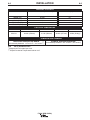
PHYSICAL DIMENSIONS
TEMPERATURE RANGES
HEIGHT
18.80in (478mm)
MODEL
K3073-1
WIDTH
14.14in (359mm)
DEPTH
26.66in (677mm)
WEIGHT
125lbs (56.6kg)*
OPERATING TEMPERATURE RANGE
Environmentally Hardened: 14°F to 131°F (-10°C to 55°C
**
)
STORAGE TEMPERATURE RANGE
Environmentally Hardened: -40°F to 185°F (-40°C to 85°C)
PROCESS
GMAW (CV)
GTAW (CC)
SMAW (CC)
FCAW-GS (CV)
FCAW-SS (CV)
OUTPUT RANGE (AMPERES)
40-500
10-500
15-500
40-500
40-500
OCV (Uo)
60
24
60
60
60
WELDING PROCESS
IP23 155º(F) Insulation Class
* Weight does not include input cord.
** Output De-rated at Temperatures above 40°C.

A-3
INSTALLATION
A-3
SELECT SUITABLE LOCATION
LOCATION AND VENTILATION FOR COOLING
Place the welder where clean cooling air can freely
circulate in through the rear louvers and out through
the case sides. Dirt, dust, or any foreign material that
can be drawn into the welder should be kept at a mini-
mum. Failure to observe these precautions can result
in excessive operating temperatures and nuisance
shutdowns.
LIFTING
Both handles should be used when lifting the FX450.
When using a crane or overhead device a lifting strap
should be connected to both handles. Do not attempt
to lift the FX450 with accessories attached to it.
STACKING
The FX450 cannot be stacked.
ENVIRONMENTAL LIMITATIONS
The FX450 is IP23 rated for use in an outdoor envi-
ronment. The FX450 should not be subjected to falling
water during use nor should any parts of it be sub-
merged in water. Doing so may cause improper oper-
ation as well as pose a safety hazard. The best prac-
tice is to keep the machine in a dry, sheltered area.
SAFETY PRECAUTIONS
ELECTRIC SHOCK can kill.
ONLY QUALIFIED PERSONNEL
SHOULD PERFORM THIS INSTALLA-
TION.
• TURN OFF INPUT POWER TO THE POWER
SOURCE AT THE DISCONNECT SWITCH OR
FUSE BOX BEFORE WORKING ON THIS
EQUIPMENT. TURN OFF THE INPUT POWER
TO ANY OTHER EQUIPMENT CONNECTED TO
THE WELDING SYSTEM AT THE DISCONNECT
SWITCH OR FUSE BOX BEFORE WORKING ON
THE EQUIPMENT.
• DO NOT TOUCH ELECTRICALLY HOT PARTS.
• ALWAYS CONNECT THE FX450 GROUNDING
LUG (LOCATED INSIDE THE RECONNECT
INPUT ACCESS DOOR) TO A PROPER SAFETY
(EARTH) GROUND.
----------------------------------------------------------------------
WARNING
FX450 (RED-D-ARC)
Do not mount the FX450 over combustible sur-
faces. Where there is a combustible surface
directly under stationary or fixed electrical equip-
ment, that surface shall be covered with a steel
plate at least .060” (1.6mm) thick, which shall
extend not less than 5.90” (150mm) beyond the
equipment on all sides.
-----------------------------------------------------------------------
INPUT AND GROUNDING CONNECTIONS
MACHINE GROUNDING
The frame of the welder must be grounded.
A ground terminal marked with the symbol
shown is located inside the reconnect/input
connection area for this purpose. See your
local and national electrical codes for proper ground-
ing methods.
HIGH FREQUENCY PROTECTION
Locate the FX450 away from radio controlled machin-
ery. The normal operation of the FX450 may adverse-
ly affect the operation of RF controlled equipment,
which may result in bodily injury or damage to the
equipment.
CAUTION
AMPS
340
375
400
450
VOLTS
34VDC
35VDC
36VDC
38VDC
TEMPERATURES
55°C
DUTY CYCLE
100%
60%
40%
20%
HIGH TEMPERATURE OPERATION
WELDER OUTPUT RATINGS AT 55°C
ELEVATED TEMPERATURES

A-4
INSTALLATION
A-4
INPUT FUSE AND SUPPLY WIRE
CONSIDERATIONS
Refer to Specification in this Installation Section for
recommended fuse, wire sizes and type of the copper
wires. Fuse the input circuit with the recommended
super lag fuse or delay type breakers (also called
"inverse time" or "thermal/magnetic" circuit breakers).
Choose input and grounding wire size according to
local or national electrical codes. Using input wire
sizes, fuses or circuit breakers smaller than recom-
mended may result in "nuisance" shut-offs from
welder inrush currents, even if the machine is not
being used at high currents.
INPUT VOLTAGE SELECTION
Welders are shipped connected for 460 Volt input
voltage. To move this connection to a different input
voltage, see the diagram located on the inside panel
in the reconnect/input connection area, also illustrat-
ed below. If the Auxiliary lead (indicated as ʻAʼ) is
placed in the wrong position and power is applied to
the machine, the machine will protect itself and dis-
play an error message:
• "Err" "058" will be shown on the display.
• The control board and switch boards will blink out
error 58 on their status leds.
• The weld output will be turned off and the control
board will force itself into an idle state.
• The machine will need to have the misconnect
condition removed before it will recover.
ELECTRIC SHOCK can kill.
ONLY A QUALIFIED ELECTRICIAN
SHOULD CONNECT THE INPUT
LEADS TO THE FX450. CONNEC-
TIONS SHOULD BE MADE IN ACCORDANCE
WITH ALL LOCAL AND NATIONAL ELECTRI-
CAL CODES AND THE CONNECTION DIAGRAM
LOCATED ON THE INSIDE OF THE RECON-
NECT/INPUT ACCESS DOOR OF THE
MACHINE. FAILURE TO DO SO MAY RESULT
IN BODILY INJURY OR DEATH.
----------------------------------------------------------------------
WARNING
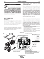
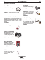
INPUT CONNECTION
(See Figure A.1)
Use a three-phase supply line. A 1.40 inch (36 mm)
diameter access hole for the input supply is located on
the case back. Connect L1, L2, L3 and ground
according to the Input Supply Connection Diagram
decal located on the internal horizontal panel.
To access the reconnect/input supply connection
blocks, remove the 8 screws that secure the case top
of the welder and remove the case top.
FX450 (RED-D-ARC)
RECONNECT TERMINAL BLOCK
• Reconnects auxiliary transformers
for the proper input voltages
POWER SUPPLY TERMINAL BLOCK
• Line Cord/Cable attaches here.
• A ground terminal marked with the symbol shown
is provided separate from this block for connecting the ground
lead of the line cord. (See your local and national electrical
codes for proper grounding methods.)
POWER SUPPLY ACCESS HOLE
• Route input power cable through this hole.
RECONNECT TERMINAL BLOCK
RECONNECT TERMINAL BLOCK
• Reconnects auxiliary transformers
for the proper input voltages
POWER SUPPLY TERMINAL BLOCK
• Line Cord/Cable attaches here.
• A ground terminal marked with the symbol shown
is provided separate from this block for connecting the ground
lead of the line cord. (See your local and national electrical
codes for proper grounding methods.)
POWER SUPPLY ACCESS HOLE
• Route input power cable through this hole.
RECONNECT TERMINAL BLOCK
FIGURE A-1

A-5
INSTALLATION
A-5
FX450 (RED-D-ARC)
Pin
A
B
C
D
E
F
Wiring
77 Remote potentiometer, 5K
76 Remote potentiometer, wiper
75 Remote potentiometer, common
Trigger, common
Trigger, input
Ground
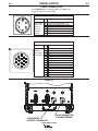
CABLE CONNECTIONS
See FIGURE A.2 for locating 6-pin and 14-pin con-
nectors on the front of the FX450.
FIGURE A.2
Function
6-pin remote
control con-
nector for
remote or
hand/foot
amptrol.
A
E
C
F
B
D
A
E
C
F
B
D
6-PIN REMOTE CONTROL CONNECTOR
Pin
A
B
C
D
E
F
G
H
I
J
K
L
M
N
Wiring
Ground
Trigger, Common
Trigger input
77 Remote potentiometer, 5K
76 Remote potentiometer, wiper
75 Remote potentiometer, common
Voltage Sense (21)
Motor (42 VAC)
Motor (42 VAC)
Function
14 pin con-
nector for
wire feeder
connectivity.
G
F
E
M
N
D
B
A
J
I
L
K
C
H
G
F
E
M
N
D
B
A
J
I
L
K
C
H
14-PIN CONNECTOR FOR WIRE FEEDER
14-PIN CONNECTOR
FOR WIRE FEEDER
6-PIN REMOTE
CONTROL CONNECTOR
14-PIN CONNECTOR
FOR WIRE FEEDER
6-PIN REMOTE
CONTROL CONNECTOR

A-6
INSTALLATION
FX450 (RED-D-ARC)
A-6
RECOMMENDED ELECTRODE AND
WORK CABLE SIZES FOR ARC WELDING
General Guidelines
Connect the electrode and work cables between the
appropriate output studs of the FX450 per the follow-
ing guidelines:
• Most welding applications run with the electrode
being positive (+). For those applications, connect
the electrode cable between the wire drive feed
plate and the positive (+) output stud on the power
source. Connect a work lead from the negative (-)
power source output stud to the work piece.
• When negative electrode polarity is required, such
as in some Innershield applications, reverse the out-
put connections at the power source (electrode
cable to the negative (-) stud, and work cable to the
positive (+) stud).
The following recommendations apply to all output
polarities and weld modes:
• Select the appropriate size cables per the
“Output Cable Guidelines” (See Table A.1).
Excessive voltage drops caused by undersized
welding cables and poor connections often result in
unsatisfactory welding performance. Always use the
largest welding cables (electrode and work) that are
practical, and be sure all connections are clean and
tight.
Note: Excessive heat in the weld circuit indicates
undersized cables and/or bad connections.
• Route all cables directly to the work and wire
feeder, avoid excessive lengths and do not coil
excess cable. Route the electrode and work cables
in close proximity to one another to minimize the
loop area and therefore the inductance of the weld
circuit.
• Always weld in a direction away from the work
(ground) connection.
CONTROL CABLE CONNECTIONS
General Guidelines
Genuine Lincoln control cables should be used at all
times (except where noted otherwise). Lincoln cables
are specifically designed for the communication and
power needs of the FX450. Most are designed to be
connected end to end for ease of extension.
Generally, it is recommended that the total length not
exceed 100 feet (30.5 m). The use of non-standard
cables, especially in lengths greater than 25 feet, can
lead to communication problems (system shutdowns),
poor motor acceleration (poor arc starting), and low
wire driving force (wire feeding problems). Always use
the shortest length of control cable possible, and DO
NOT coil excess cable.
Regarding cable placement, best results will be
obtained when control cables are routed separate
from the weld cables. This minimizes the possibility of
interference between the high currents flowing
through the weld cables, and the low level signals in
the control cables.
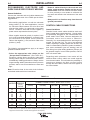
** Tabled values are for operation at ambient temperatures of 104°F(40°C) and below. Applications above 104°F(40°C) may require cables
larger than recommended, or cables rated higher than 167°F(75°C).
OUTPUT CABLE GUIDELINES
CABLE SIZES FOR COMBINED LENGTHS OF ELECTRODE AND WORK CABLES
(RUBBER COVERED COPPER - RATED 167°F or 75°C)**
AMPERES
200
200
250
250
250
250
300
300
350
400
400
500
PERCENT
DUTY
CYCLE
60
100
30
40
60
100
60
100
40
60
100
60
0 to 50Ft.
(0 to15m)
2
2
3
2
1
1
1
2/0
1/0
2/0
3/0
2/0
50 to 100Ft.
(15 to 30m)
2
2
3
2
1
1
1
2/0
1/0
2/0
3/0
2/0
100 to 150 Ft.
(30 to 46m)
2
2
2
1
1
1
1
2/0
2/0
2/0
3/0
3/0
150 to 200 Ft.
(46 to 61m)
1
1
1
1
1
1
1/0
2/0
2/0
3/0
3/0
3/0
200 to 250 Ft.
(61 to 76m)
1/0
1/0
1/0
1/0
1/0
1/0
2/0
3/0
3/0
4/0
4/0
4/0
TABLE A.1

B-1
OPERATION
FX450 (RED-D-ARC)
B-1
SAFETY PRECAUTIONS
Read this entire section of operating instructions
before operating the machine.
ELECTRIC SHOCK can kill.
• Unless using cold feed feature, when
feeding with gun trigger, the
electrode and drive mechanism are
always electrically energized and
could remain energized several
seconds after the welding ceases.
• Do not touch electrically live parts or electrodes
with your skin or wet clothing.
• Insulate yourself from the work and ground.
• Always wear dry insulating gloves.
FUMES AND GASES can be
dangerous.
• Keep your head out of fumes.
• Use ventilation or exhaust to remove
fumes from breathing zone.
WELDING SPARKS can cause
fire or explosion.
• Keep flammable material away.
• Do not weld on containers that have
held combustibles.
ARC RAYS can burn.
• Wear eye, ear, and body protection.
Observe additional guidelines detailed in the
beginning of this manual.
WARNING
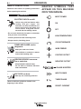
INPUT POWER
ON
OFF
HIGH TEMPERATURE
CIRCUIT BREAKER
WIRE FEEDER
POSITIVE OUTPUT
NEGATIVE OUTPUT
3 PHASE INVERTER
INPUT POWER
THREE PHASE
DIRECT CURRENT
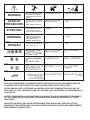
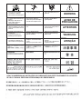
GRAPHIC SYMBOLS THAT
APPEAR ON THIS MACHINE
OR IN THIS MANUAL

B-2
OPERATION
B-2
FX450 (RED-D-ARC)
PRODUCT DESCRIPTION
The FX450 is a multi-process CC/CV DC inverter and
is rated for 450 amps, 38 volts at a 60% duty cycle.
This machine is intended for both factory and field
operation. It comes in a compact, rugged case that is
designed for portability and outdoor use with an IP23
environmental rating. The user interface of the FX450
is simple and intuitive. Weld modes are selected by a
4 position selector switch. Volts and Amps are dis-
played on an easy to view LED display, and the amps
and volts are set by a large output control knob. A hot
start toggle selector switch and an arc control knob
allow for finer tuning of the welding arc. The FX450
operates on 380V, 460V, or 575V 50hz or 60hz
power.
DUTY CYCLE
The FX450 is capable of welding at a 100% duty cycle
(continuous welding) at 400 amps rated output. The
60% rating is 450 amps base off of a 10 minute cycle -
6 minutes on time and 4 minutes off time. The maxi-
mum output of the machine is 500 amps.
The FX450 is also rated for Desert Duty, elevated
temperature operation, in a 55°C(131°F) ambient.
The machine is output de-rated for this application.
DESIGN FEATURES
• Severe Duty Design for outdoor use (IP23 rating).
• Passive Power Factor Correction – reliably gives
95% power factor for lower installation costs.
• 89% Efficiency rating – reduces electrical utility
costs.
• Simple user interface - designed with the operator in
mind. Getting setup for the weld is several clicks
away and even the most novice welder can be confi-
dent he is setup properly.
• F.A.N. (fan as needed). Cooling fan runs when the
output is energized and for a 5 minute cool down
period after output is disabled.
• Thermal protection by thermostats with Thermal
Indicator LED.
• Error Codes display on LED screen for ease of trou-
ble shooting.
• Electronic over current protection.
• Input voltage misconnection protection.
• Utilizes digital signal processing and microprocessor
control.
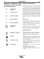
OPEN CIRCUIT
VOLTAGE
INPUT VOLTAGE
OUTPUT VOLTAGE
INPUT CURRENT
OUTPUT CURRENT
PROTECTIVE
GROUND
WARNING or CAUTION
Explosion
Dangerous Voltage
Shock Hazard
GRAPHIC SYMBOLS THAT
APPEAR ON THIS MACHINE
OR IN THIS MANUAL
U
0
U
1
U
2
I
1
I
2

B-3
OPERATION
B-3
RECOMMENDED PROCESSES AND
EQUIPMENT
RECOMMENDED PROCESSES
The FX450 is designed for CC-SMAW, CC-GTAW (lift tig),
CV-GMAW, CV-FCAW-SS and CV-FCAW-GS welding
processes. CAG (arc gouging) is also supported.
PROCESS LIMITATIONS
The FX450 is suitable only for the processes listed.
EQUIPMENT LIMITATIONS
Operating Temperature Range is -10° C to + 55° C.
Output De-rated at Temperatures above 40°C.
FX450 (RED-D-ARC)
Note: The
FX450 is not compatible with 115V Wire Feeders.
K3073-1
K2327-5
K2149-1
K1842-10
3100211
FX450
LF-72 Bench Model
Work Lead Package
10 Ft. Weld Power Cable
Harris Regulator and gas hose
Basic Package
K857
K857-1
K870
K963-3
Remote Output Control (25 feet)
Remote Output Control (100 feet)
Foot Amptrol
Hand Amptrol
Common Optional Kits
All Models
LF-72
LF-74
LN-10
DH-10
LN-25 Pro
Compatible Wire Feeders
COMMON EQUIPMENT PACKAGES

B-4
OPERATION
B-4
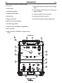
CASE FRONT CONTROL DESCRIPTIONS
(See Figure B.1)
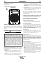
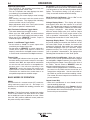
1. Power Switch
2. Voltage Display Meter
3. Amperage Display Meter
4. Thermal LED
5. Output Control Dial
6. Weld Process Selector Switch
7. Hot Start Toggle Switch
8. Output Control Local/Remote Toggle Switch
9. Arc Control Dial
10. Weld Terminals On/Remote toggle selector
switch
FX450 (RED-D-ARC)
1
2
3
4
5
6
7
8
9
10
11
12
13
14
15
1
2
3
4
5
6
7
8
9
10
11
12
13
14
15
FIGURE B.1
11. Wire feeder voltmeter polarity selection toggle
switch
12. Circuit breaker reset button for the 14-pin wire
feeder connector
13. 14-pin wire feeder circular connector
14. 6-pin remote circular connector
15. Positive and negative welding output studs

B-5
OPERATION
B-5
FX450 (RED-D-ARC)
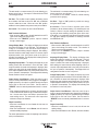
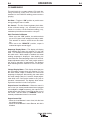
CASE BACK CONTROL
(See Figure B.2)
1. Input Power Cord Access Hole.
1
1
FIGURE B.2
COMMON WELDING PROCEDURES
MAKING A WELD
The serviceability of a product or structure utiliz-
ing the welding programs is and must be the sole
responsibility of the builder/user. Many variables
beyond the control of The Lincoln Electric
Company affect the results obtained in applying
these programs. These variables include, but are
not limited to, welding procedure, plate chemistry
and temperature, weldment design, fabrication
methods and service requirements. The available
range of a welding program may not be suitable
for all applications, and the build/user is and must
be solely responsible for welding program selec-
tion.
The FX450 is a multi-process inverter welder. The
Weld Process Selector Switch is used to set the
desired weld mode. The FX450 has 4 selectable
welding modes:
1. SMAW – This is a CC (constant current) weld
mode used for the SMAW stick welding process.
2. GTAW – This is a CC (constant current) weld
mode used for the GTAW TIG welding process.
3. CV – This is CV (constant voltage) weld mode used
for welding the GMAW MIG welding process and
the FCAW-GS, flux cored gas shielded welding
process.
4. CV-Innershield – This is a CV (constant voltage)
weld mode used for welding the FCAW-SS, flux
cored self shielded welding process
The FX450 is also capable of gouging. Gouging can
be done in either the SMAW mode or the CV and CV-
Innershield modes.
In addition to the weld process selector switch, a hot
start toggle, output control dial and arc control dial are
provided to setup and fine tune the welding procedure.
WELD CONTROLS AND DISPLAYS
Weld Process Selector Switch
4 Position switch used to select the welding process.
Hot Start Toggle Switch
The Hot Start control regulates the starting current at
arc initiation. Hot Start can be set to “Off” and no
additional current is added at arc start. When set to
the “On” position, additional current (relative to the
preset current) is added at arc initiation.
Arc Control Dial
Full range selection of arc control from -10 to +10. In
CV mode, this control is an inductance control. In
stick mode, the control adjusts the arc force.
Output Control Dial
Output control is conducted by a single turn poten-
tiometer. (Adjustment is indicated by the meters.)
When in Remote Mode, this control sets the maximum
welding current of the remote device. For example, full
depression of a foot or hand amptrol results in the pre-
set level of current.
Voltage Display Meter
• Prior to CV operation (current flow), the meter dis-
plays desired preset voltage value.
• Prior to STICK or TIG operation, the meter displays
the Open Circuit Voltage of the Power Source or four
dashes if the output has not been turned on.
• During welding, this meter displays actual average
volts.
• After welding, the meter holds the actual voltage
value for 5 seconds. The displays blink indicating that
the machine is in the "hold" period.
• Output adjustment while in the "hold" period results in
the "prior to operation" characteristics.
WARNING
POWER-UP SEQUENCE
When power is applied to the FX450, the displays will
illuminate and display the voltage and/or amperage
settings.

B-6
OPERATION
B-6
Amperage Display Meter
• Prior to STICK or TIG operation (current flow), the
meter displays preset current value.
• Prior to CV operation, the meter displays four dash-
es indicating non-presettable AMPS.
• During welding, this meter displays actual average
amps.
• After welding, the meter holds the actual current
value for 5 seconds. The displays blink indicating
that the machine is in the "hold" period.
•Output adjustment while in the "hold" period results
in the "prior to operation" characteristics
Weld Terminals On/Remote Toggle Switch
• This switch determines the trigger location.
• When set to the “ON” position, the weld terminals
are at OCV (open circuit voltage) and ready to weld.
• When set to the “REMOTE” position, output is
enabled through a remote trigger.
Control - Local/Remote Toggle Switch
• Set the switch to “Local” to control output at the
machine by the Output Control dial.
• Set the switch to “REMOTE” to control output via a
remote device (K857 hand amptrol or K870 foot
amptrol) connected to the 6-pin remote connector
or a wire feeder connected to the 14-pin connector.
Thermal Light
• This status light indicates when the power source
has been driven into thermal overload. If the output
terminals were "ON", the output will be turned back
on once the unit cools down to an acceptable tem-
perature level. If the unit was operating in the
"REMOTE" mode, the trigger will need to be
opened before or after the thermal has cleared and
closed after the machine has cooled down to an
acceptable temperature to establish output.
BASIC MODES OF OPERATION
SMAW
This weld mode is a constant current (CC) mode fea-
turing continuous control from 15 – 500 amps. It is
intended for the SMAW stick welding processes and
arc gouging.
Hot Start - The Hot Start control regulates the starting
current at arc initiation. Hot Start can be set to “Off”
and no additional current is added at arc start. When
set to the “On” position, additional current (relative to
the preset current) at arc initiation.
FX450 (RED-D-ARC)
Arc Control - The Arc Control regulates the Arc Force
to adjust the short circuit current. The minimum setting
(-10) will produce a "soft" arc and will produce minimal
spatter. The maximum setting (+10) will produce a
"crisp" arc and will minimize electrode sticking.
Weld Terminals On/Remote – Set to “On” so the
machine is in the ready to weld state.
Voltage Display Meter – This display will display
three dashed lines when the machine is in the idle
state. This indicates that voltage is not settable in this
weld mode. While output is enabled, the actual weld-
ing voltage is displayed. After welding, the meter
holds the actual voltage value for 5 seconds. Output
adjustment while in the "hold" period results in the
"prior to operation" characteristics. The displays blink
indicating that the machine is in the "hold" period.
Amperage Display Meter – This display will display
the pre-set welding current when the machine is in the
idle state. While output is enabled, the actual weld
amperage is displayed. After welding, the meter holds
the actual amperage value for 5 seconds. Output
adjustment while in the "hold" period results in the
"prior to operation" characteristics. The displays blink
indicating that the machine is in the "Hold" period.
Output Control Local/Remote – When the control is
set to local (no remote potentiometer/control plugged
into the 6-pin or 14-pin connectors), the output is con-
trolled through the Output Control Dial on the front of
the FX450. Set this switch to “REMOTE” when an
external potentiometer/control is connected.
• When a remote potentiometer is connected, the out-
put control on the FX450 and the remote act as a
master/slave configuration. Use the control dial on
the FX450 to pre-set the maximum welding current.
The remote will control output from minimum to the
pre-set maximum.
Output Control Dial
• When the Local/Remote is set to Local, this dial
sets the welding amperage.
• When the Local/Remote is set to Remote, this dial
sets the maximum welding amperage. The remote
potentiometer than controls the amperage from min-
imum to this pre-set maximum.

B-7
OPERATION
B-7
GTAW
This weld mode is a constant current (CC) mode featuring con-
tinuous control from 10 – 500 amps. It is intended for the GTAW
TIG welding processes.
Hot Start - The Hot Start control regulates the starting current
at arc initiation. Hot Start can be set to “Off” and no additional
current is added at arc start. When set to the “On” position,
additional current (relative to the preset current) at arc initiation.
Arc Control – This control is not used in the GTAW mode.
Weld Terminals On/Remote
• When set to the “ON” position, the weld terminals are at OCV
(open circuit voltage) and ready to weld.
• When set to the “REMOTE” position, output is enabled
through a remote trigger.
Voltage Display Meter – This display will display three dashed
lines when the machine is in the idle state. This indicates that
voltage is not settable in this weld mode. While output is
enabled, the actual welding voltage is displayed. After welding,
the meter holds the actual voltage value for 5 seconds. Output
adjustment while in the "hold" period results in the "prior to
operation" characteristics. The displays blink indicating that the
machine is in the "hold" period.
Amperage Display Meter – This display will display the pre-set
welding current when the machine is in the idle state. While
output is enabled, the actual weld amperage is displayed. After
welding, the meter holds the actual amperage value for 5 sec-
onds. Output adjustment while in the "hold" period results in the
"prior to operation" characteristics. The displays blink indicating
that the machine is in the "hold" period.
Output Control Local/Remote – When the control is set to
local (no remote potentiometer/control plugged into the 6-pin or
14-pin connectors), the output is controlled through the Output
Control Dial on the front of the FX450. Set this switch to
“REMOTE” when an external potentiometer/control is connect-
ed.
• When a remote potentiometer is connected, the output control
on the FX450 and the remote act as a master/slave configura-
tion. Use the control dial on the FX450 to pre-set the maxi-
mum welding current. The remote will control output from
minimum to the pre-set maximum.
Output Control Dial
• When the Local/Remote is set to Local, this dial sets the
welding amperage.
• When the Local/Remote is set to Remote, this dial sets the
maximum welding amperage.
The remote potentiometer controls the amperage from minimum
to this pre-set maximum.
FX450 (RED-D-ARC)
CV-GAS
This weld mode is a constant voltage (CV) mode featuring con-
tinuous control from 10 to 45 volts.
It is intended for the GMAW, FCAW-GS, MCAW welding
processes and arc gouging.
Hot Start – Toggle to “ON” position to provide more energy
during the start of a weld.
Arc Control – The Arc Control regulates pinch effect
(Inductance). At the minimum setting (-10), minimizes pinch and
results in a soft arc. Low pinch settings are preferable for weld-
ing with gas mixes containing mostly inert gases. At the maxi-
mum setting (+10), maximizes pinch effect and results in a crisp
arc. High pinch settings are preferable for welding FCAW-GS
and GMAW with CO
2
.
Weld Terminals On/Remote
• When set to the “ON” position, the weld terminals are at OCV
(open circuit voltage) and ready to weld. This selection is
used for across the arc wire feeders.
• When set to the “REMOTE” position, output is enabled
through a remote trigger.
Amperage Display Meter – This display will display three
dashed lines when the machine is in the idle state. This indi-
cates that amperage is not settable in this weld mode. While
output is enabled, the actual welding amperage is displayed.
After welding, the meter holds the actual amperage value for 5
seconds. Output adjustment while in the "hold" period results in
the "prior to operation" characteristics. The displays blink indi-
cating that the machine is in the "hold" period.
Voltage Display Meter – This display will display the pre-set
welding voltage when the machine is in the idle state. While out-
put is enabled, the actual weld amperage is displayed. After
welding, the meter holds the actual voltage value for 5 seconds.
Output adjustment while in the "hold" period results in the "prior
to operation" characteristics. The displays blink indicating that
the machine is in the "hold" period.
Output Control Local/Remote – When the control is set to
local (no remote potentiometer/control plugged into the 6-pin or
14-pin connectors), the output is controlled through the Output
Control Dial on the front of the FX450. Set this switch to
“REMOTE” when an external potentiometer/control is connect-
ed.
Output Control Dial
• When the Local/Remote is set to Local, this dial sets the
welding voltage.
• When the Local/Remote is set to Remote, this dial is disabled.

B-8
OPERATION
B-8
CV-INNERSHIELD
This weld mode is a constant voltage (CV) mode fea-
turing continuous control from 10 to 45 volts. It is
intended for the FCAW-SS welding process and arc
gouging.
Hot Start – Toggle to “ON” position to provide more
energy during the start of a weld.
Arc Control – The Arc Control regulates pinch effect.
At the minimum setting (-10), minimizes pinch and
results in a soft arc. At the maximum setting (+10),
maximizes pinch effect and results in a crisp arc.
Weld Terminals On/Remote
• When set to the “ON” position, the weld terminals
are at OCV (open circuit voltage) and ready to weld.
This selection is used for across the arc wire feed-
ers.
• When set to the “REMOTE” position, output is
enabled through a remote trigger.
Amperage Display Meter – This display will display
three dashed lines when the machine is in the idle
state. This indicates that amperage is not settable in
this weld mode. While output is enabled, the actual
welding amperage is displayed. After welding, the
meter holds the actual amperage value for 5 seconds.
Output adjustment while in the "hold" period results in
the "prior to operation" characteristics. The displays
blink indicating that the machine is in the "hold" peri-
od.
Voltage Display Meter – This display will display the
pre-set welding voltage when the machine is in the
idle state. While output is enabled, the actual weld
amperage is displayed. After welding, the meter holds
the actual voltage value for 5 seconds. Output adjust-
ment while in the "hold" period results in the "prior to
operation" characteristics. The displays blink indicat-
ing that the machine is in the "hold" period.
Output Control Local/Remote – When the control is
set to local (no remote potentiometer/control plugged
into the 6-pin or 14-pin connectors), the output is con-
trolled through the Output Control Dial on the front of
the FX450. Set this switch to “REMOTE” when an
external potentiometer/control is connected.
Output Control Dial
• When the Local/Remote is set to Local, this dial sets
the welding voltage.
• When the Local/Remote is set to Remote, this dial is
disabled
FX450 (RED-D-ARC)
Page is loading ...
Page is loading ...
Page is loading ...
Page is loading ...
Page is loading ...
Page is loading ...
Page is loading ...
Page is loading ...
Page is loading ...
Page is loading ...
-
 1
1
-
 2
2
-
 3
3
-
 4
4
-
 5
5
-
 6
6
-
 7
7
-
 8
8
-
 9
9
-
 10
10
-
 11
11
-
 12
12
-
 13
13
-
 14
14
-
 15
15
-
 16
16
-
 17
17
-
 18
18
-
 19
19
-
 20
20
-
 21
21
-
 22
22
-
 23
23
-
 24
24
-
 25
25
-
 26
26
-
 27
27
-
 28
28
-
 29
29
-
 30
30
-
 31
31


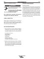
Lincoln Electric Red-D-Arc FX450 Operating instructions
- Category
- Welding System
- Type
- Operating instructions
Ask a question and I''ll find the answer in the document
Finding information in a document is now easier with AI
Related papers
-
Lincoln Electric Power Feed 11 User manual
-
-
Lincoln Electric Power Wave i400 Operating instructions
-
-
-
-
-
-
-