
© February, 2010 by South Bend Lathe Co. Revised July, 2011 (BL)
For Collet Attachments Mfg. Since 10/09
FOR LATHE MODELS: SB1012–15, SB1037–39, SB1049–52
MODEL SB1264/SB1268
COLLET ATTACHMENT

Customer Service
We stand behind our machines. If you have any service questions, parts requests or general questions
about your purchase, feel free to contact us.
South Bend Lathe Co.
P.O. Box 2027
Bellingham, WA 98227
Fax: (360) 676-1075 (International)
Fax: (360) 734-1639 (USA Only)
Email: [email protected]
Updates
For your convenience, any updates to this manual will be available to download free of charge
through our website at:
www.southbendlathe.com
Scope of Manual
This manual helps the reader understand the machine, how to prepare it for operation, how to control
it during operation, and how to keep it in good working condition. We assume the reader has a basic
understanding of how to operate this type of machine, but that the reader is not familiar with the
controls and adjustments of this specific model. As with all machinery of this nature, learning the
nuances of operation is a process that happens through training and experience. If you are not an
experienced operator of this type of machinery, read through this entire manual, then learn more
from an experienced operator, schooling, or research before attempting operations. Following this
advice will help you avoid serious personal injury and get the best results from your work.
Manual Feedback
We've made every effort to be accurate when documenting this machine. However, errors sometimes
happen or the machine design changes after the documentation process—so the manual may not
exactly match your machine. If a difference between the manual and machine leaves you in doubt,
contact our customer service for clarification.
We highly value customer feedback on our manuals. If you have a moment, please share your
experience using this manual. What did you like about it? Is there anything you would change to
make it better? Did it meet your expectations for clarity, professionalism, and ease-of-use?
South Bend Lathe, Inc.
C
/O Technical Documentation Manager
P.O. Box 2027
Bellingham, WA 98227
Email: [email protected]

Table of Contents
OPERATION .................................................................... 13
Operation Overview ...........................................13
Collet Attachment Removal .............................. 13
Accessories ......................................................... 14
MAINTENANCE ............................................................. 15
Maintenance Schedule .......................................15
Parts Diagram ....................................................16
Parts List ............................................................ 16
Warranty ............................................................ 17
INTRODUCTION ...............................................................2
About This Collet Attachment ............................ 2
Capabilities ......................................................... 2
Specifications.......................................................2
Features ..............................................................2
Identification ........................................................3
SAFETY ................................................................................4
Understanding Risks of Machinery ....................4
Basic Machine Safety .......................................... 4
Additional Collet Attachment Safety ..................6
PREPARATION .................................................................7
Things You'll Need ............................................... 7
Unpacking ............................................................7
Inventory ..............................................................7
Cleaning & Protecting .........................................8
Installation ........................................................... 9
Test Run ............................................................. 12

INTRODUCTION
-2-
For Machines Mfg. Since 10/09
Model SB1264/SB1268
INTRODUCTION
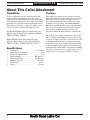
About This Collet Attachment
Specifications
• ColletSize .......................................5-C Collets
• QuickRemovalDesign ...............................Yes
• AllMetalConstruction ..............................Yes
• ColletAdapter .............................. MT-6 to 5-C
• InstallationTime .......................... 45 Minutes
• ShippingWeight ............................... 26.5 lbs.
• NetWeight ........................................... 25 lbs.
• Origin ................................................... Taiwan
If many workpieces of the same diameter are
to be turned or threaded on the lathe, and
productivity is dependent on the ease of loading
and unloading workpieces, this collet attachment
provides the capability of increased productivity.
This collet attachment accepts 5-C collets and is
easily installed and removed from the lathe.
The Model SB1264 Collet Attachment fits the
following South Bend Lathes: SB1039, SB1049,
SB1050, SB1051, SB1052.
Model SB1268 Collet Attachment fits the
following South Bend Lathes: Model SB1012,
SB1013, SB1014, SB1015, SB1037, SB1038.
Capabilities
This collet attachment takes advantage of the
South Bend factory-made collet port in the lathe
gear cover. This accessory installs easily on
the listed South Bend Lathes without having
to modify the gear cover. The Model SB1264/
SB1268 is capable of delivering years of trouble-
free service. It is manufactured with the same
high-quality workmanship, materials, and
tolerances South Bend machinery is known for.
For ease of use, a collet attachment lever locks
the 5-C collet and workpiece in place. To ensure
accurate clamping pressure, a chuck sleeve with
a thumb operated lock lever allows the length
of the draw tube to be lengthened or shortened
in fine increments. For speedy installation and
removal of the entire collet attachment assembly,
this unit is designed with a quick-release clevis
and pin that has an overall slide-out design.
Features
For Machines Mfg. Since 10/09 Model SB1264/SB1268
-3-
INTRODUCTION
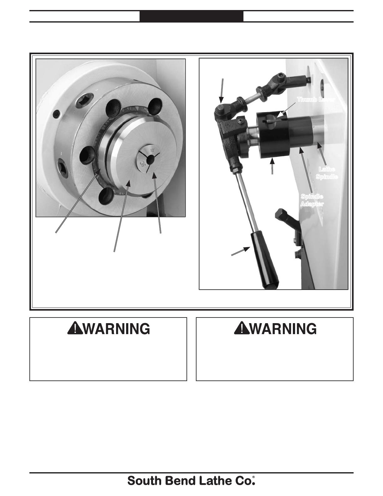
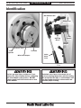
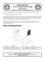
Identification
Adjusting
Sleeve
Serious personal injury could occur if you
connect the lathe to power before completing
the collet adapter setup process. DO NOT
connect power until instructed to do so later
in this manual.
Untrained users have an increased risk of
seriously injuring themselves with this tooling.
Do not operate the lathe or collet adapter until
you have understood this entire manual and
received proper training.
Outboard
View
Inboard View
Collet
Closer
Lever
Spindle
Adapter
Lathe
Spindle
Thumb Lever
5-C Collet
MT-6 Collet Adapter
Quick-Release Pin
Lathe
Spindle

SAFETY
-4-
For Machines Mfg. Since 10/09
Model SB1264/SB1268
SAFETY
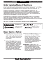
Understanding Risks of Machinery
Operating all machinery and machining equipment can be dangerous or relatively safe depending
on how it is installed and maintained, and the operator's experience, common sense, risk awareness,
working conditions, and use of personal protective equipment (safety glasses, respirators, etc.).
The owner of this machinery or equipment is ultimately responsible for its safe use. This
responsibility includes proper installation in a safe environment, personnel training and usage
authorization, regular inspection and maintenance, manual availability and comprehension,
application of safety devices, integrity of cutting tools or accessories, and the usage of approved
personal protective equipment by all operators and bystanders.
The manufacturer of this machinery or equipment will not be held liable for injury or property
damage from negligence, improper training, machine modifications, or misuse. Failure to read,
understand, and follow the manual and safety labels may result in serious personal injury, including
amputation, broken bones, electrocution, or death.
The signals used in this manual to identify hazard levels are defined as follows:
Death or catastrophic
harm WILL occur.
Moderate injury or fire
MAY occur.
Death or catastrophic
harm COULD occur.
Machine or property
damage may occur.
Basic Machine Safety
Owner’s Manual: All machinery and machining
equipment presents serious injury hazards
to untrained users. To reduce the risk of
injury, anyone who uses THIS item MUST
read and understand this entire manual
before starting.
Personal Protective Equipment:
Operating or
servicing this item may expose the user
to flying debris, dust, smoke, dangerous
chemicals, or loud noises. These hazards
can result in eye injury, blindness, long-
term respiratory damage, poisoning,
cancer, reproductive harm or hearing loss.
Reduce your risks from these hazards
by wearing approved eye protection,
respirator, gloves, or hearing protection.
Trained/Supervised Operators Only: Untrained
users can seriously injure themselves
or bystanders. Only allow trained and
properly supervised personnel to operate
this item. Make sure safe operation
instructions are clearly understood. If
electrically powered, use padlocks and
master switches, and remove start switch
keys to prevent unauthorized use or
accidental starting.
Guards/Covers:
Accidental contact with
moving parts during operation may cause
severe entanglement, impact, cutting,
or crushing injuries. Reduce this risk by
keeping any included guards/covers/doors
installed, fully functional, and positioned
for maximum protection.

For Machines Mfg. Since 10/09 Model SB1264/SB1268
-5-
SAFETY
Entanglement: Loose clothing, gloves, neckties,
jewelry or long hair may get caught in
moving parts, causing entanglement,
amputation, crushing, or strangulation.
Reduce this risk by removing/securing
these items so they cannot contact moving
parts.
Mental Alertness: Operating this item with
reduced mental alertness increases the
risk of accidental injury. Do not let a
temporary influence or distraction lead to a
permanent disability! Never operate when
under the influence of drugs/alcohol, when
tired, or otherwise distracted.
Safe Environment:
Operating electrically
powered equipment in a wet environment
may result in electrocution; operating near
highly flammable materials may result in a
fire or explosion. Only operate this item in
a dry location that is free from flammable
materials.
Electrical Connection: With electically powered
equipment, improper connections to the
power source may result in electrocution
or fire. Always adhere to all electrical
requirements and applicable codes when
connecting to the power source. Have all
work inspected by a qualified electrician to
minimize risk.
Disconnect Power: Adjusting or servicing
electrically powered equipment while it
is connected to the power source greatly
increases the risk of injury from accidental
startup. Always disconnect power
BEFORE any service or adjustments,
including changing blades or other tooling.
Secure Workpiece/Tooling:
Loose workpieces,
cutting tools, or rotating spindles can
become dangerous projectiles if not
secured or if they hit another object during
operation. Reduce the risk of this hazard
by verifying that all fastening devices are
properly secured and items attached to
spindles have enough clearance to safely
rotate.
Chuck Keys or Adjusting Tools:
Tools used to
adjust spindles, chucks, or any moving/
rotating parts will become dangerous
projectiles if left in place when the machine
is started. Reduce this risk by developing
the habit of always removing these tools
immediately after using them.
Work Area:
Clutter and dark shadows increase
the risks of accidental injury. Only operate
this item in a clean, non-glaring, and well-
lighted work area.
Properly Functioning Equipment:
Poorly
maintained, damaged, or malfunctioning
equipment has higher risks of causing
serious personal injury compared to
those that are properly maintained.
To reduce this risk, always maintain
this item to the highest standards and
promptly repair/service a damaged or
malfunctioning component. Always follow
the maintenance instructions included in
this documentation.
Unattended Operation:
Electrically powered
equipment that is left unattended while
running cannot be controlled and is
dangerous to bystanders. Always turn the
power OFF before walking away.
Health Hazards: Certain cutting fluids and
lubricants, or dust/smoke created when
cutting, may contain chemicals known to
the State of California to cause cancer,
respiratory problems, birth defects,
or other reproductive harm. Minimize
exposure to these chemicals by wearing
approved personal protective equipment
and operating in a well ventilated area.
Difficult Operations:
Attempting difficult
operations with which you are unfamiliar
increases the risk of injury. If you
experience difficulties performing the
intended operation, STOP! Seek an
alternative method to accomplish the
same task, ask a qualified expert how the
operation should be performed, or contact
our Technical Support for assistance.

-6-
For Machines Mfg. Since 10/09
Model SB1264/SB1268
SAFETY
Additional Collet Attachment Safety
Stopping the Lathe by Hand: Stopping
the spindle by putting your hand on the
workpiece creates an extreme risk of
entanglement, impact, crushing, friction, or
cuttinghazards.Neverattempttoslowor
stop the lathe by using your hand. Allow the
spindle to come to a stop on its own or use
the brake (if equipped).
Projectile Hazard: A camlock or chuck key
left in the spindle or chuck can become a
dangerous projectile if the lathe is started.
And never walk away from the lathe leaving
any of these tools in the spindle or chuck.
Always remove all keys and tooling after use.
Crushing Hazard: Chucks can be heavy
and difficult to grasp, which can lead to
crushed fingers or hands if mishandled.
Get assistance when installing or removing
chucks to reduce this risk. Protect your
hands and the precision ground ways by
using a chuck cradle or piece of plywood over
the ways of the lathe when servicing chucks.
Avoiding Entanglement: Disconnect the lathe
from power before installing and removing
the collet attachment, collets, and work
pieces. Accidental lathe startup can cause
severe injury or death.
Tool Selection: Cutting with an incorrect or
dull tool increases the risk of accidental
injury because extra force is required, which
increases risk of breaking or dislodging
components. Always select the right cutter
for the job, and make sure it is sharp. A
correct, sharp tool decreases strain and
provides a better finish.
Securing the Workpiece: Before starting the
lathe, make sure the collet and workpiece
are properly secured with the draw tube,
and that the collet attachment lever is in the
locked position. A thrown workpiece may
cause severe injury or even death.
Long Stock Safety: Long stock can whip
violently if not properly supported, causing
serious impact injury and damage to the
lathe. Reduce this risk by supporting any
stock that extends from the chuck/headstock
more than three times its own diameter.
Always turn long stock at slow speeds.
Speed Rates: Operating the lathe at the wrong
speed can cause nearby parts to break or the
workpiece to come loose, which could result
in them becoming dangerous projectiles.
Large workpieces must be turned at slow
speeds. Always use the appropriate feed and
speed rates.

PREPARATION
For Machines Mfg. Since 10/09 Model SB1264/SB1268
-7-
PREPARATION
Things You'll Need
During the setup process, operation, and
maintenance of your machine, you'll need the
following items:
For Assembly:
• Mineral Spirits
• SafetyGlasses
• Shop Vacuum
• Assistant
• Oil Can with Way Oil
• CottonShopRags
• HexWrench5mm
• HexWrench8mm
• Open-EndWrench19mm
• Open-EndWrench24mm
• DrillBit5mmor#9(0.196")
• DrillBit
1
⁄8"
• CenterPunch
1
⁄4"
• ThreadingTapM6-1
• Tube of Thread Sealant
• ElectricHand-Drill
• Hacksaw
• Bench-MountedVise
Unpacking
This item was carefully packaged to prevent
damage during transport. If you discover any
damage, please immediately call Customer
Service at (360) 734-1540 for advice. You may
need to file a freight claim, so save the containers
and all packing materials for possible inspection
by the carrier or its agent.
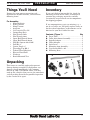
Inventory
If you can't find an item on this list, check the
mounting location on the collet attachment or
examine the packaging materials carefully.
Occasionally we pre-install certain components
for shipping purposes.
If any nonproprietary parts are missing (e.g. a
nut or a washer), we will gladly replace them; or
for the sake of expediency, replacements can be
obtained at your local hardware store.
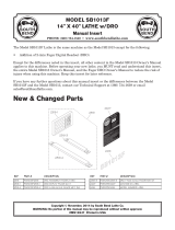
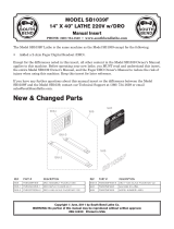
Contents: (Figure 1) Qty
A. Draw Tube ......................................................1
B. Collet Attachment Assembly .........................1
C. Spindle Adapter .............................................1
D. Collet Adapter ................................................ 1
E. Lock Lever ......................................................1
F. Mounting Arm Assembly ............................... 1
G. Cap Screws M6-1 x 20 ....................................3
H. Mounting Base ..............................................1
Figure 1. Inventory
A
H
G
F
B
C
D
E
-8-
For Machines Mfg. Since 10/09
Model SB1264/SB1268
PREPARATION
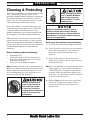
The unpainted surfaces are coated at the factory
with a heavy-duty rust preventative that
prevents corrosion during shipment and storage.
The benefit of this rust preventative is that it
works very well. The downside is that it can be
time-consuming to thoroughly remove.
Be patient and do a careful job when cleaning
and removing the rust preventative. The time
you spend doing this will reward you with
smooth-sliding parts and a better appreciation
for the proper care of the unpainted surfaces.
Although there are many ways to successfully
remove the rust preventative, we have cleaned
thousands of machines and found the following
process to be the best balance between efficiency
and minimized exposure to toxic fumes or
chemicals.
Before cleaning, gather the following:
s $ISPOSABLErags
s #LEANERDEGREASER (certain citrus-based
degreasers work extremely well and they
have non-toxic fumes)
s 3AFETYGLASSESDISPOSABLEGLOVES
Note: Automotive degreasers, mineral spirits, or
7$sCANBEUSEDTOREMOVERUSTPREVENTATIVE
Before using these products, though, test them
on an inconspicuous area of a painted area to
make sure they will not damage it.
Basic steps for removing rust preventative:
1. Put on safety glasses and disposable gloves.
2. #OATALLSURFACESTHATHAVERUSTPREVENTATIVE
with a liberal amount of your cleaner or
degreaser and let them soak for a few
minutes.
3. Wipe off the surfaces. If your cleaner or
degreaser is effective, the rust preventative
will wipe off easily.
Note: To clean off thick coats of rust preventative
on flat surfaces, such as beds or tables, use
A0,!34)#PAINTSCRAPERTOSCRAPEOFFTHE
majority of the coating before wiping it off
WITHYOURRAG$ONOTUSEAMETALSCRAPEROR
it may scratch the surface.)
4. Repeat Steps 2–3 as necessary until clean,
then coat all unpainted surfaces with a
quality metal protectant or light oil to
prevent rust.
GAS
Gasoline and petroleum
products have low flash
points and can explode
or cause fire if used for
cleaning. Avoid using these
products to remove rust
preventative.
Many cleaning solvents are
toxic if inhaled. Minimize
your risk by only using
these products in a well
ventilated area.
Avoid chlorine-based solvents, such as
acetone or brake parts cleaner that may
damage painted surfaces. Always follow the
manufacturer’s instructions when using any
type of cleaning product.
Cleaning & Protecting
For Machines Mfg. Since 10/09 Model SB1264/SB1268
-9-
PREPARATION
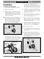
Installation
To install the collet attachment:
1. DISCONNECTLATHEFROMPOWER!
2. Remove the lathe chuck.
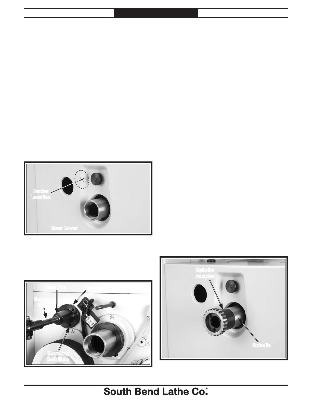
3. Looking through the hole in the gear cover,
mark the center location of the hole on the
headstock (Figure 2). The center location
is where the center of the collet attachment
base must be mounted.
Note: Depending on date of lathe manufacture,
the mounting location shown in Figure 3
may have been pre-drilled at the factory to
mount the collet attachment base. If this is
the case, remove the three fasteners that
plug the holes and proceed to Step 8.
5. To reduce the risk of metal shavings
contaminating the headstock gear case, have
your assistant vacuum the filings while you
drill and cut the threads into the headstock.
6. Carefully, so as not to run the drill bit too
deep into the headstock gearbox, center-drill
the three mounting holes with an
1
⁄8"drillbit
approximately
1
⁄2"deep.
7. Usinga5mmor#9drillbitandanM6-1tap,
drill and cut threads in the headstock case
for the three mounting holes.
8. Apply a coat of thread sealant on the three
M6-1 x 20 cap screws. Next, use a 5mm hex
wrench to fasten the base to the headstock
with the three cap screws.
9. Threadthesupportstudapproximately1"
into the base. Then, using a 19mm wrench,
tighten the jam nut shown in Figure 3.
10. Reinstall the gear cover.
11. Using a lightly oiled rag, wipe the inboard
and outboard ends of the lathe spindle until
they are clean.
12. Wipe the spindle adapter clean with the
same rag. Next, thread the adapter onto the
spindle in a counterclockwise direction until
the adapter seats flush with the spindle as
shown in Figure 4.
Figure 4. Spindle adapter installation.
Spindle
Spindle
Adapter
Figure 2. Base mounting location behind cover.
Gear Cover
Center
Location
4. Put on your safety glasses, then using a
1
⁄4"
center punch and the base shown in Figure
3 as a template, mark the three mounting
bolt holes on the side of the headstock.
Figure 3. Base positioning on the headstock.
Jam Nut
Support
Stud
Mounting Base
Mounting
Bolt Hole
-10-
For Machines Mfg. Since 10/09
Model SB1264/SB1268
PREPARATION
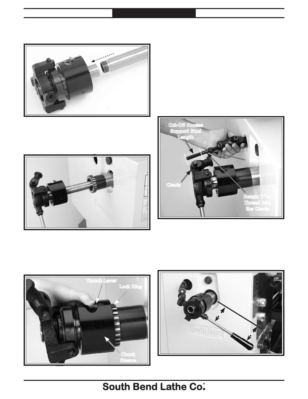
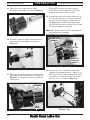
Figure 5. Draw tube installation.
13. Thread the draw tube into the collet
attachment assembly, as shown in Figure 5.
When fully installed, the lock ring will
be hidden and the thumb lever will have
dropped down into a lock ring slot.
16. Position the collet attachment lock lever so
it is parallel with the gear cover, and mark
how much of the support stud must be cut
off (Figure 8 ) in order for the lever to be
parallel with the cover surface. Next, cut off
the excess support stud length.
Note: The amount to be cut-off is dependent on
your desired lever position.
14. Carefully insert the collet attachment draw
tube into the lathe spindle, as shown in
Figure 6.
Figure 6. Collet attachment installation.
15. When the chuck sleeve contacts the lock ring,
press down on the thumb lever, as shown in
Figure 7, and engage the lock ring with the
chuck sleeve.
Figure 7. Chuck sleeve installation.
Thumb Lever
Chuck
Sleeve
Lock Ring
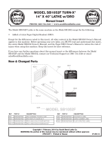
17. Remove the clevis and thread it onto the
supportstudapproximately1".Adjustitso
when the clevis is reinstalled onto the collet
attachment, the lock lever is parallel with
the gear cover, as shown in Figure 9.
Figure 9. Clevis positioning so lock lever is parallel
with gear cover.
Figure 8. Support stud sizing.
Retain 1" to
Thread Into
the Clevis
Cut-Off Excess
Support Stud
Length
Clevis
Hex Nut
For Machines Mfg. Since 10/09 Model SB1264/SB1268
-11-
PREPARATION
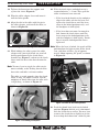
18. Tighten the hex nut on the support stud
against the clevis (Figure 8).
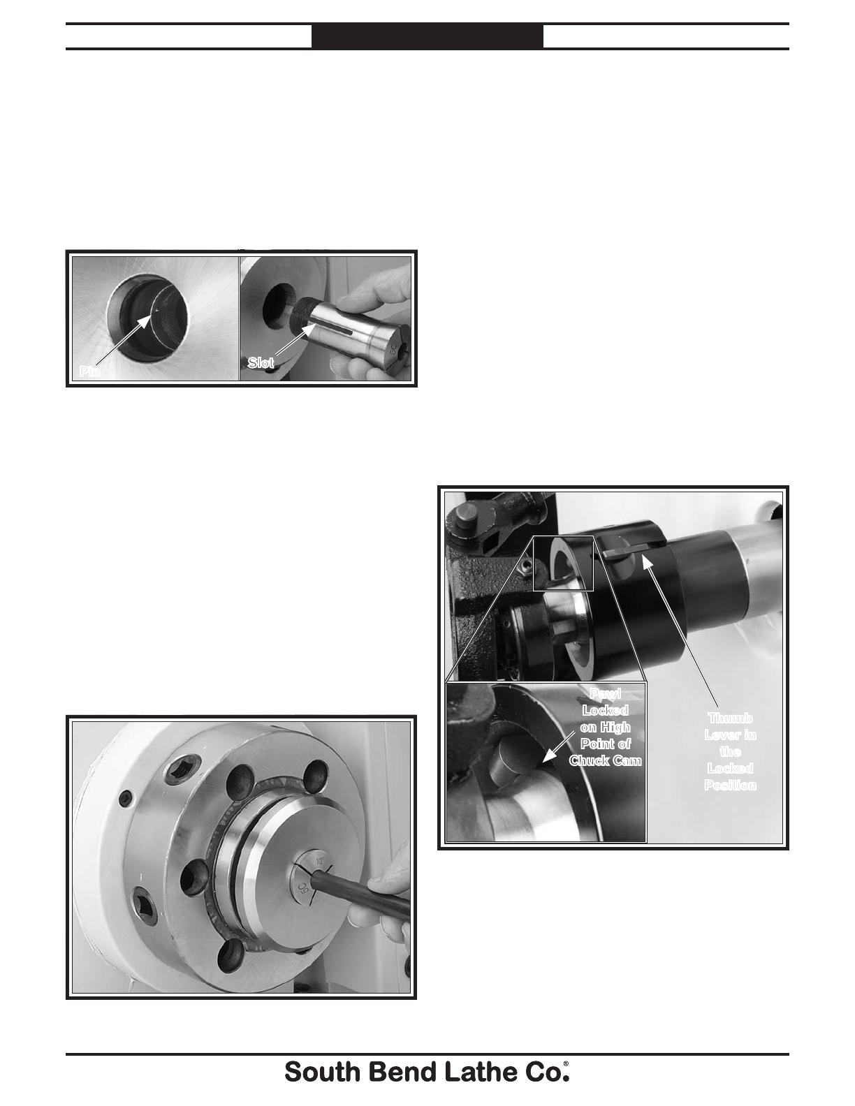
19. Wipe the collet adapter clean and insert it
into the lathe spindle.
20. Align the slot in the collet with the pin in
the collet adapter, and install the collet, as
shown in Figure 10.
22. With the chuck sleeve unlocked, rotate it
counterclockwise
3
⁄4 –1 turn. Then, pull the
collet attachment lever outward.
— If the lever locks loosely or the workpiece
slips in the collet, release the lever and
tighten the chuck sleeve until the lever
snaps to the locked position easily, and
the workpiece is held tightly.
— If the lever does not move far enough to
lock, loosen the chuck sleeve until the
lever snaps to the locked position easily
and the workpiece is held tightly. Do not
force it into the locked position if over
tightened.
Note: When the lever is locked, the pawls will be
positioned on the highest point of the chuck
cam, and there will be a gap of approxi-
mately 16mm exposing the pawls, as shown
in Figure 12.
21. While holding the collet against the collet
adapter with your right hand, use your left
hand to push down on the chuck-sleeve
thumb lever (Figure 7) and rotate the chuck
sleeve until the draw tube threads onto the
collet.
Note: You may have to wiggle the collet attach-
ment assembly, so the leading thread of the
draw tube and collet catch one another.
The collet is seated properly when the chuck
sleeve is snug, the collet is seated, and the
workpiece or dowel slides into the collet with
a slight drag, as shown in Figure 11.
Pin
Slot
Figure 10. Collet alignment.
Figure 11. Installing a workpiece.
Chuck
Cam
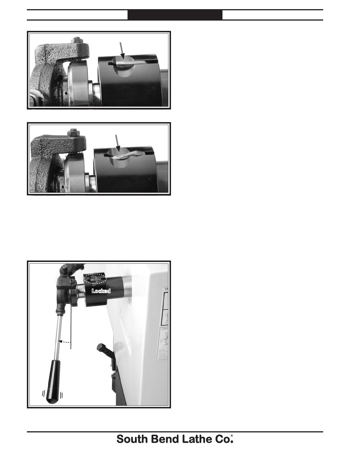
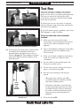
23. Push the thumb lever back into its locked
position (Figures 13–14),soitishorizontal
with the chuck sleeve surface. You may have
to rotate the chuck sleeve slightly to get the
lever to drop back down into a lock ring slot.
Figure 12. Pawls in the locked position.
Thumb
Lever in
the
Locked
Position
Pawl
Locked
on High
Point of
Chuck Cam
-12-
For Machines Mfg. Since 10/09
Model SB1264/SB1268
PREPARATION
Figure 13. Chuck sleeve thumb lever locked.
Test Run
Once the assembly is complete, test run your
lathe with the collet attachment installed to
make sure the unit is ready for regular operation.
The test run consists of verifying the collet
attachment is concentric with the lathe spindle
and is free of vibration.
If, during the test run, you detect an unusual
noise or vibration, stop using lathe immediately,
and correct the problem.
If you still cannot remedy a problem, contact our
Tech Support at (360) 734-1540.
To test run lathe with collet attachment
installed:
1. Make sure you have read the safety
instructions at the beginning of the manual
and that the collet attachment is setup
properly.
2. Lock a small dowel or workpiece in the collet,
and verify that the lathe spindle rotates
freely by hand.
3. Make sure all tools and objects used during
setup are cleared away from the collet
attachment.
4. Set the lathe to a low spindle speed, and
disengage any feed levers.
5. Put on safety glasses, connect the lathe to
power, and turn the lathe ON.
6. Run the lathe through its full range of
speeds.
— When operating correctly, the collet
attachment operates smoothly without
vibration or rubbing noises.
— Investigate and correct unusual noises
or vibrations before operating the collet
attachment further. Always disconnect
the collet attachment from power when
investigating or correcting potential
problems.
7. Turn the lathe OFF.
24. At this point, the chuck sleeve and the collet
attachment lever should be locked and
positioned outward from the gear cover as
shown in Figure 15. The workpiece or dowel
must be held firmly without slippage when
pulled by hand.
Lever
Snaps
Into
Locked
Position
Locked
Figure 15. Collet attachment completely locked and
ready for use.
Locked
Figure 14. Chuck sleeve thumb lever unlocked.
Unlocked
OPERATION
For Machines Mfg. Since 10/09 Model SB1264/SB1268
-13-
OPERATION
Operation Overview
The purpose of the operation section is to
familiarizeyouwiththebasiccontrols,
terminology, capabilities, and adjustments that
are necessary to use this collet attachment.
To complete a typical operation, the operator
does the following:
1. Selectsthecorrect-sizedcolletforthe
diameter of the workpiece.
2. Verifies that no burrs exist on the workpiece.
3. Aligns the slot in the collet with the pin in
the collet adapter, and inserts the collet and
workpiece into the adapter.
4. Threads the draw tube onto the collet by
turning the chuck sleeve until the collet is
seated and the clutch sleeve is snug.
5. Applies the collet attachment lever to close
To reduce the risk of
serious injury when using
this collet attachment, read
and understand this entire
manual before beginning
any operations.
Loose hair, clothing, or
jewelry could get caught
in machinery and cause
serious personal injury.
Keep these items away
from moving parts at all
times to reduce this risk.
During operation, small
metal chips may become
airborne, leading to serious
eye injury. Wear safety
glasses to reduce this risk.
the collet, and verifies the workpiece is
clamped securely.
— If clamping is too loose or too tight, the
operator releases the lock lever and
rotates the chuck sleeve to attain lever
locking and workpiece clamping.
6. Installs the required inboard and outboard
workpiece support with stands, the steady
rest, or the follow rest.
7. Installs the required tooling, puts on safety
glasses, and begins lathe operations.
To complete remove the collet attachment
from the lathe:
1. DISCONNECTLATHEFROMPOWER!
2. Place a wooden board on the lathe ways to
protect the ways.
3. Support the collet with your right hand.
With your left hand, unlock the collet
attachment lever and turn the chuck sleeve
to un-thread the draw tube from the collet.
4. When the collet is free, remove the knurled
pin, and slide the collet attachment assembly
out of the spindle.
5. With your right hand, hold the spindle
collet adapter to keep it from falling out of
the lathe spindle, and with your left hand,
insert a wooden dowel into the spindle from
the outboard side and tap the spindle collet
adapter free from the lathe spindle.
Collet Attachment
Removal

-14-
For Machines Mfg. Since 10/09
Model SB1264/SB1268
ACCESSORIES
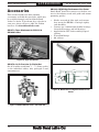
Accessories
This section includes the most common
accessories available for your lathe, which may
be available through your local South Bend
Lathe Co. dealer. If you do not have a dealer in
your area, please call us at (360) 734-1540 or
email us at [email protected].
SB1239—MT#5 High Performance Live Center
South Bend
®
brand live centers are the best cen-
ters in the industry made with pride and uncom-
promising quality.
• Shaftsaremadeofalloysteelandvacuum
heattreatedtoHRC60±1forhighrigidity
and durability.
• Centersuseacombinationofrollerbearings,
thrust ball bearings and ball bearings.
• ApplicableforCNClathesandhighspeed
turning.
• Waterproofdesign.
• 60°centers.
SB1271—Taper Attachment for SB1016 &
SB1036 Lathes.
Figure 18. Model SB1239 High Performance Live
Center.
1.73" 2.83" 4.29"
8.86"
2.99"
1.378"
60°
Figure 16. Taper attachment.
SB1271
Figure 17. Model SB1279 10 Pc. 5-C Collet Set.
SB1279—10 Pc. Precision 5–C Collet Set
Setof10colletssizedfrom
1
⁄8"-
3
⁄4".Samequality
as the individual collets, only packaged in one
convenient set.

MAINTENANCE
For Machines Mfg. Since 10/09 Model SB1264/SB1268
-15-
MAINTENANCE
Maintenance Schedule
For optimum performance from your collet attach-
ment, follow this maintenance schedule and refer
to any specific instructions given in this section.
Cleaning your collet attachment is relatively easy.
Vacuum excess metal chips away, and wipe off the
remaining metal parts with a rag that is moist-
ened with the machine oil you use to lubricate
your lathe.
Always disconnect
machine from power before
performing maintenance or
serious personal injury may
result.
!
Daily Check:
• Cleanandinspectalltaperedmating
surfaces.
• Inspectforloosemountingcapscrews.
• Inspect collet adapter for missing pin.
• Inspect for missing or cracked pins or loose
set screws.
• Inspect for any other unsafe condition.
Monthly Check:
• Cleanandde-burrdrawtubethreads.
• Applyoiltoallmetalsurfacestopreventrust
and maintain smooth operation.
Storage:
• To prevent rust and corrosion, apply way
oil to all metal surfaces, and store the collet
attachment in a wooden box or cabinet that is
dry and free of paints and chemicals.
-16 -
For Machines Mfg. Since 10/09
Model SB1264/SB1268
PARTS
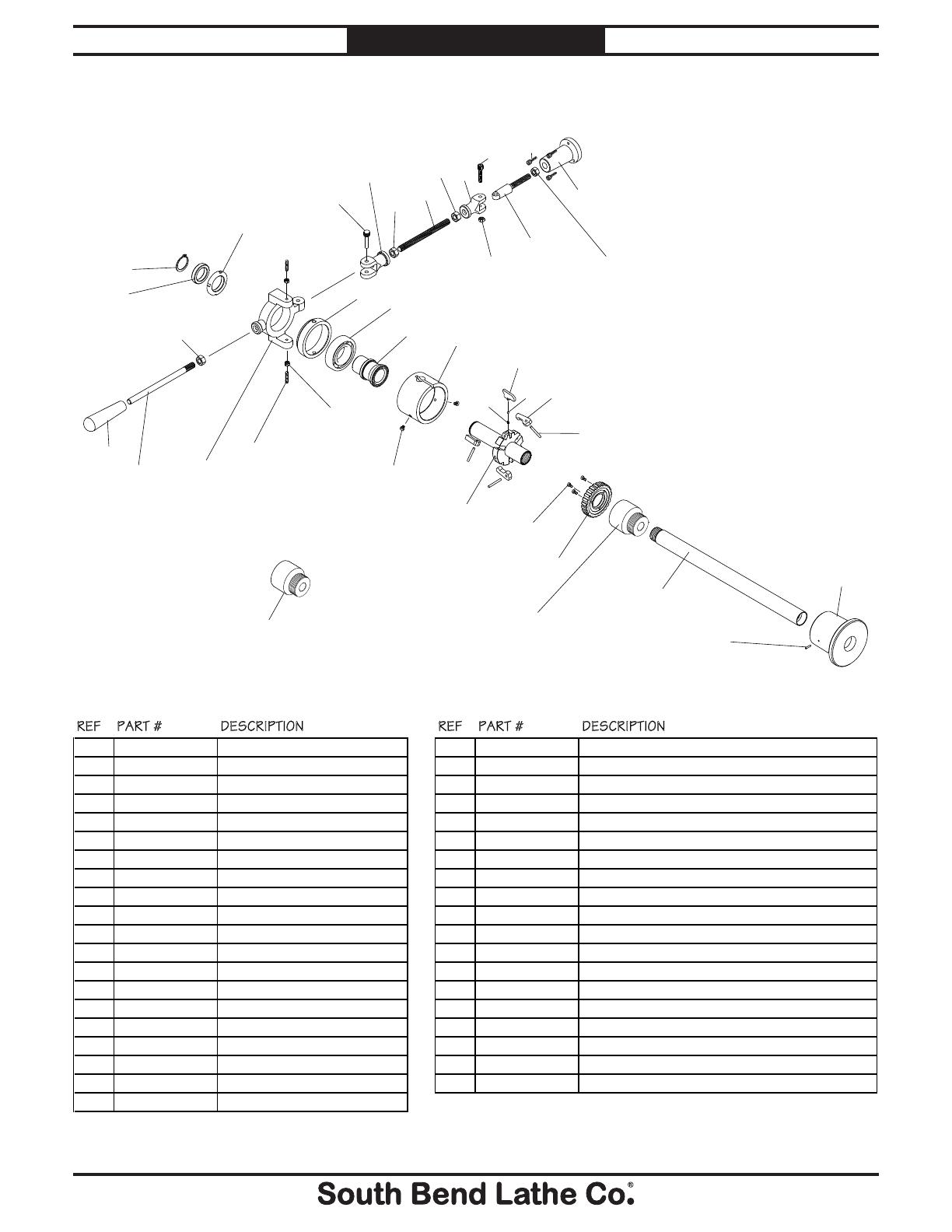
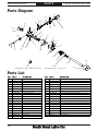
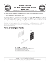
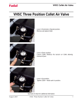
Parts Diagram
REF PART # DESCRIPTION REF PART # DESCRIPTION
1 PSB1268001 KNURLED PIN 21 PSB1268021 LOCK RING
2 PSB1268002 CLEVIS 22 PCAP33M CAP SCREW M5-.8 X 12
3 PSB1268003 THREADED STUD 1/2-20 x 6 23 PCAP02M CAP SCREW M6-1 X 20
4 PSB1268004 MOUNTING BASE 24 PSB1264024 SPINDLE ADAPTER 41.5-16 V1.06.09 (SB1039)
5 PCAP143M CAP SCREW M10-1.5 X 50 24V2 PSB1264024V2 SPINDLE ADAPTER 43.5-16 V2.07.11 (SB1039)
6 PSB1268006 LOCK YOKE 24 PSB1268024 SPINDLE ADAPTER M55-2 LH (SB1012)
7 PSB1268007 LEVER 25 PRP44M ROLL PIN 3 X 10
8 PSB1268008 PLASTIC KNOB 1/2-20 26 PSB1264026 COLLET ADAPTER MT5/5C (SB1039)
9 PSB1268009 YOKE RING 26 PSB1268026 COLLET ADAPTER MT6/5C (SB1012)
10 PSB1268010 CHUCK RING 27 PSB1264027 DRAW TUBE 21.06 (SB1039)
11 PSB1268011 CHUCK HOUSING 27 PSB1268027 DRAW TUBE 24.5" (SB1012)
12 PSB1268012 BALL BEARING 6208ZZ KOYO 28 PCAP18M CAP SCREW M4-.7 X 8
13 PN03M HEX NUT M8-1.25 29 PSB1268029 PIVOT PIN
14 PSS74M SET SCREW M8-1.25 X 35 30 PSB1268030 LOCK BALL
15 PR37M EXT RETAINING RING 32MM 31 PSB1268031 COMPRESSION SPRING
16 PSB1268016 SPANNER NUT 32 PLN05M LOCK NUT M10-1.5
17 PSB1268017 COLLAR 33 PSB1268033 CLEVIS STUD M16-2
18 PSB1268018 THUMB LEVER 34 PN01 HEX NUT 1/2-20
19 PSB1268019 LOCK PAWL 35 PN13M HEX NUT M16-2
20 PSB1268020 ADJUSTMENT SLEEVE
Parts List
20
16
6
17
15
9
13
14
12
1
10
2
34
3
8
7
4
34
32
33
35
5
2
11
19
18
29
31
30
28
23
27
21
26
25
22
34
24V2
(FOR MODELS MFG. SINCE 07.11)
24
(FOR MODELS MFG. FROM 06.09-06.11)

For Machines Mfg. Since 10/09 Model SB1264/SB1268
-17-
WARRANTY
This quality product is warranted by South Bend Lathe Company to the original buyer for one year
from the date of purchase. This warranty does not apply to consumable parts, or defects due to any
kind of misuse, abuse, negligence, accidents, repairs, alterations or lack of maintenance. We do not
reimburse for third party repairs. In no event shall we be liable for death, injuries to persons or
property, or for incidental, contingent, special or consequential damages arising from the use of our
products.
We do not warrant or represent that this machine complies with the provisions of any law, act, code,
regulation, or standard of any domestic or foreign government, industry, or authority. In no event
shall South Bend’s liability under this warranty exceed the original purchase price paid for this
machine. Any legal actions brought against South Bend Lathe Company shall be tried in the State of
Washington, County of Whatcom.
This is the sole written warranty for this machine. Any and all warranties that may be implied by
law, including any merchantability or fitness, for any purpose, are hereby limited to the duration of
this warranty. To take advantage of this warranty, contact us by mail or phone to give us the details
of the problem you are having.
Thank you for your business and continued support.
Warranty

Printed In Taiwan #CR12466
-
 1
1
-
 2
2
-
 3
3
-
 4
4
-
 5
5
-
 6
6
-
 7
7
-
 8
8
-
 9
9
-
 10
10
-
 11
11
-
 12
12
-
 13
13
-
 14
14
-
 15
15
-
 16
16
-
 17
17
-
 18
18
-
 19
19
-
 20
20


Ask a question and I''ll find the answer in the document
Finding information in a document is now easier with AI
Related papers
-
 South bend SB1272 Owner's manual
-
 South bend SB1014 Owner's manual
-
 South bend SB1037F Owner's manual
-
 South bend SB1038F Owner's manual
-
 South bend SB1013F Owner's manual
-
 South bend SB1015F Owner's manual
-
 South bend SB1013 Owner's manual
-
 South bend SB1012 Owner's manual
-
 South bend SB1039F insert Owner's manual
-
 South bend SB1052F User manual


Other documents
-
Central Machinery 10 in. 12 Speed Bench Drill Press Owner's manual
-
Southbend SB1012 User manual
-
-
-
-
-
-
-
 FADAL VH5C User manual
-
Nakanishi IG - 400 Owner's manual
