
Sensing and Internet of Things
Issue 10
81521
m WARNING
IMPROPER INSTALLATION
• Consult with local safety agencies and their
requirements when designing a machine-control link,
interface, and all control elements that affect safety.
• Strictly adhere to all installation instructions.
Failure to comply with these instructions could result in
death or serious injury.
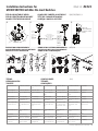
MOUNT, WIRE, AND SEAL THE SWITCH
m WARNING
IMPROPER OPERATION
• Ensure switch actuator achieves sufficient travel for
positive opening of normally closed (NC) contacts to
occur.
Failure to comply with these instructions could result in
death or serious injury.
1. Refer to:
• Page 5 for adjustments
• Pages 8 to 12 for specific travel distances for each
switch code and specifications
• Page 5 for proper application of limit switches
• Page 13 to 18 for switch mounting dimensions
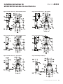
2. Perform adjustments (if desired):
• Head orientation (Figure 1, page 5)
• Actuation direction (Figure 2, page 5)
• Side rotary switches with 36 drive lever positions
(Figure 3, page 5):
3. Mount switch at top corners of switch using two M4 or #8
screws. For GLD products torque screws to 2,7 Nm to 3,4
Nm [24 in-lb to 30 in-lb]. For GLC & GLE products torque
screws to 3,1 Nm to 3,7 Nm [27 in-lb to 33 in-lb].
4. Remove screws on cover plate.
5. Connect stranded wire (0,75 mm
2
to 2,3 mm
2
, 1814 AWG)
or solid wire (0,75 mm
2
to 1,5 mm
2
, 1816 AWG) to contact
block terminals (use 90 °C wire when ambient temperature
is over 75 °C). Torque switch terminal screws to 0,8 Nm to
1,0 Nm [7 in-lb to 9 in-lb].
6. Seal conduit opening according to instructions in PK
80112.
7. Reassemble cover plate, and torque cover screws to 0,5 Nm
[4.4 in-lb].
Installation Instructions for the MICRO SWITCH Global Limit Switches (GLS MINDIN Series)
Instrucciones de instalación para los MICRO SWITCH interruptores limite global (serie GLS MINDIN)
Einbauanweisungen für den MICRO SWITCH Global Endschalter (Serie GLS MINDIN)
Instructions d’installation du MICRO SWITCH fin de course mondiales (série GLS MINDIN)
Istruzioni per l’installazione del MICRO SWITCH finecorsa globali (Serie GLS MINDIN)
Instruções de Instalação para o MICRO SWITCH de limite global (Série GLS MINDIN)
MICRO SWITCH 全球限位开关(GLS MINDIN 系列)安装指南
Ui 300V ac/dc metal
Ui 300 Vdc/600 Vac plastic
UL EN 50047
EN6094751
CCC GB 14048.5 - 2001*
EN455452 HL 3 (GLC & GLE Series switches only)
m ADVERTENCIA
INSTALACIÓN INCORRECTA
• Consulte las normas de seguridad y sus requisitos al
realizar el diseño del enlace de control de una máquina,
la interfaz, y los elementos de control que afecten a la
seguridad.
• Siga estrictamente todas las instrucciones para la instalación.
El incumplimiento de estas recomendaciones puede
ocasionar lesiones graves o peligro de muerte.
MONTAJE, CABLEADO Y SELLADO DEL
INTERRUPTOR
m ADVERTENCIA
FUNCIONAMIENTO INCORRECTO
• Asegúrese que el actuador del interruptor tenga la
suficiente carrera para que se produzca la apertura positiva
de los contactos normalmente cerrados (NC)..
El incumplimiento de estas recomendaciones puede
ocasionar lesiones graves o peligro de muerte.
1. Consulte:
• Página 5 para obtener información sobre ajustes
• Páginas 8 a 12 para obtener las distancias específicas
de carrera para cada código de interruptor y especifi-
caciones
• Página 5 para obtener información sobre la aplicación
correcta de los interruptores de final de carrera
• Página 13 a 18 para obtener las dimensiones de mon-
taje del interruptor
2. Realice ajustes (si lo desea):
• Orientación del cabezal (Figura 1, página 5)
• Dirección del accionamiento (Figura 2, página 5)
• Interruptores de rotación lateral con 36 posiciones de
la palanca de impulsión (Figura 3, página 5):
3. Monte el interruptor colocando dos tornillos M4 o N.º 8 en
sus ángulos superiores. Para los productos GLD, ajuste los
tornillos empleando un torque de 2,7 Nm a 3,4 Nm [de 24
in-lb a 30 in-lb]. Para los productos GLC y GLE, ajuste los
tornillos empleando un torque de 3,1 Nm a 3,7 Nm [de 27
in-lb a 33 in-lb].
4. Retire los tornillos de la tapa.
5. Conecte cable trenzado (de 0,75 mm
2
a 2,3 mm
2
, 1814
AWG) o sólido (de 0,75 mm
2
a 1,5 mm
2
, 1816 AWG) en
los terminales del bloque de contactos (utilice cable de 90
°C cuando la temperatura ambiente es mayor de 75 °C).
Ajuste los tornillos empleando un torque de 0,8 Nm a 1,0
Nm [de 7 in-lb a 9 in-lb].
6. Selle la entrada del conducto según las instrucciones
incluidas en PK 80112.
7. Vuelva a montar la tapa y ajuste empleando un torque de
0,5 Nm [4,4 in-lb].
Page is loading ...
Page is loading ...
Page is loading ...

Sensing and Internet of Things 5
Installation Instructions for
MICRO SWITCH GLS Min-Din Limit Switches
ISSUE 10 81521
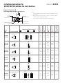
Contact Closed Contacto cerrado Kontakt geschlos-
sen
Contact fermé Contatto chiuso Contato Fechado
触点已闭合
Contact Open Contacto abierto Kontakt offen Contact ouvert Contatto aperto Contato Aberto
触点已开启
Differential Travel Carrera diferencial Differenzwinkel Course différen-
tielle
Corsa differenziale Percurso Diferen-
cial
差动行程
Free Position Posición libre Freistellung Position libre Posizione libera Posição Livre
自由位置
Operating Posi-
tion 1
Posición de func-
ionamiento 1
Schaltpunkt 1 Position de com-
mutation 1
Posizione di funzi-
onamento 1
Posição de Opera-
ção 1
工作位置 1
Positive Opening
1 to IEC 94751
Apertura positiva
1 según IEC 947
51
Zwangsöffnung 1
gemäß IEC 947
51
Ouverture positive
1 selon CEI 947
51
Apertura forzata
1 Conforme alla
norma IEC 947
51
Abertura Positiva
1 para IEC 947
51
正极开启 1 至
IEC 94751
Differential Travel
1
Carrera diferen-
cial 1
Differenzweg 1 Course différenti-
elle 1
Corsa differen-
ziale 1
Percurso Diferen-
cial 1
差动行程 1
Over Travel Sobrecarrera Nachlaufweg Surcourse Oltre corsa Sobrepercurso
超程
Maximum Operat-
ing Force
Fuerza de funcio-
namiento máxima
Maximale Betäti-
gungskraft
Force de commu-
tation maximum
Forza massima di
intervento
Força Máxima de
Operação
最大操纵力
Maximum Discon-
nect Force
Fuerza de descon-
exión máxima
Maximale Öff-
nungskraft
Force de décon-
nexion maximum
Forza massima di
scollegamento
Força Máxima de
Desconexão
最大切断力
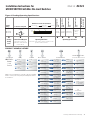
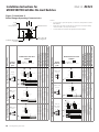
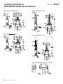
1.
90°
90°
90°
90°
2.
Half-moon of
internal plunger
to back
(as shown) or
front:
CW/CCW
Actuation.
Half-moon of
internal plunger
to right
(as shown):
CCW only
Actuation.
Half-moon of
internal plunger
to left:
CW only
Actuation
The four ribs
on the external plunger
must be aligned
to the slots
in the metal body
when re-inserting.
3.
10°
10°
10° x 36
(36 incr
emental
positions of the
lever.)
FIELD ADJUSTABLE HEAD CAMPO DE CABEZA AJUSTABLE 现场可调节操作头
FIELD VERSTELLBAREM KOPF TÊTE DE CHAMP RÉGLABLE
CAMPO TESTA REGOLABILE CABEÇA CAMPO AJUSTÁVE
OPERATION REQUIREMENTS REQUISITOS DE FUNCIONAMIENTO 操作要求
ANFORDERUNGEN AN DEN BETRIEB EXIGENCES DE FONCTIONNEMENT
REQUISITI PER L’ESERCIZIO REQUISITOS DE OPERAÇÃO
TERMS CONDICIONES 术语
BEDINGUNGEN TERMES
TARIFFE CONDIÇÕES

6 sensing.honeywell.com
Installation Instructions for
MICRO SWITCH GLS Min-Din Limit Switches
ISSUE 10 81521
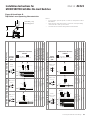
Designation and Utilization
Category
Rated Operational Current Ie (A) at Rated Operational Voltage Ue (V)
24 V 120 V 240 V 380 V 480 V 600 V
ac15 A300 – 6 A 3 A – – –
ac15 A600 – 6 A 3 A 1.9 A 1.5 A 1.2 A
dc13 Q300 2.8 A 0.55 A 0.27 A – – –
Rated thermal current (Ith) 10 A
Sealing
GLC/GLE: IP66; NEMA 1, 4, 12, 13
GLD: IP67; NEMA 1, 4X, 12, 13 (4X indoor use only)
Rated impulse withstand (Uimp) 2500 V
Pollution degree 3
Rated insulation voltage (Ui) 300 V, 600 V
Operating temperature range 40 °C to 85 °C [40 °F to 185 °F]
Short-circuit protective device (type/maxi-
mum rating)
Class J fuse (10 A/600 V)
Expected mechanical life up to 10,000,000 operations
Conditional short-circuit current 1000 A
Electrical rating for gold-plated contacts 10 mA to 100 mA, 1 Vac/Vdc to 50 Vac/Vdc
• Low Voltage Directive 2006/95/EC
• Machinery Directive 2006/42/EC only as directives relate to the components being used in a safety function
• IEC/EN 6094751
Designation and utilization category Categoría de designación y utilización Bezeichnung und Verwendungskategorie
Rated operational current Ie (A) at rated operational
voltage Ue (V)
Corriente operativa nominal Ie (A) a voltaje opera-
tivo nominal Ue (V)
Nominaler Betriebsstrom Ie (A) bei nominaler Betriebsspannung Ue (V)
Rated thermal current (Ith) Corriente térmica nominal (Ith) Nominaler thermischer Strom (Ith)
Rated impulse withstand (Uimp) Resistencia de impulso nominal (Uimp) Nominale Impulsspannung (Uimp)
Rated insulation voltage (Ui) Voltaje de aislamiento nominal (Ui) Nominale Isolationsspannung (Ui)
Short-circuit protective device (type/maximum
rating)
Dispositivo de protección contra cortocircuito
(tipo/valor nominal)
KurzschlußSchutzeinrichtung (Typ/Maximalleistung)
Conditional short-circuit current Corriente condicional de cortocircuito Bedingter Kurzschlußstrom
Electrical rating for gold-plated contacts Clasificación eléctrica para contactos bañados
en oro
Schaltvermögen von vergoldeten Kontaken
Sealing Sellado Schutzart
Pollution degree Nivel de contaminación Emissionsgrad
Operating temperature range Límites de temperatura de funcionamiento Betriebstemperaturbereich
Expected mechanical life Vida mecánica esperada Erwartete mechanische Lebensdauer
Operations Operaciones Schaltspiele
Complies with: Cumple con: Entspricht:
• Low Voltage Directive 2006/95/EC • Directiva de bajo voltaje 2006/95/EEC • NiederspannungsRichtlinie 2006/95/EG
• Machinery Directive 2006/42/EC only as the
directives relate to the components being used in a
safety function.
• Directiva de maquinarias 2006/42/EEC solo en
lo que se refiere a componentes que se utilizan en
una función de seguridad.
• MaschinenRichtlinie 2006/42/EG, soweit sich diese auf die Komponenten bezieht, die als Sicherungs-
vorrichtungen verwendet werden.
Désignation et catégorie d’utilisation Denominazione e categoria d’impiego Categoria de designação e utilização
体系及应用类别
Courant de fonctionnement nominal Ie (A) à la
tension de fonctionnement nominale Ue(V)
Corrente nominale di esercizio Ie (A) alla tensione
nominale di esercizio Ue (V)
Corrente operacional nominal Ie (A) na tensão
operacional nominal Ue (V)
额定工作电压 Ue (V) 下的额定工作电流 Ie (A)
Courant thermique nominal (Ith) Corrente termica nominale (Ith) Corrente térmica nominal (Ith) 额定热电流 (Ith)
Tension nominale de tenue au choc (Uimp) Resistenza agli impulsi nominale (Uimp) Resistência nominal ao impulso (Uimp) 额定冲击耐受 (Uimp)
Tension d’isolement nominale (Ui) Tensione di isolamento nominale (Ui) Tensão de isolamento nominal (Ui) 额定绝缘电压 (Ui)
Dispositif de protection contre les courts-circuits
(type/valeur nominale maximum)
Dispositivo di protezione per cortocircuito (valore
nominale tipico/massimo)
Dispositivo protetor contra curto-circuito (tipo/
nominal máxima)
短路保护器件(类型/最大等级)
Courant de court-circuit conditionnel Corrente di cortocircuito condizionale Corrente condicional de curto-circuito
限制短路电流
Caractéristiques électriques de contacts plaqués or Classificazione elettrica per contatti placcati oro Classificações elétricas para contatos banhados
a ouro
镀金触点电气额定值
Etanchéité Grado di protezione Vedação
密封
Indice de pollution Grado di inquinamento Grau de poluição
污染程度
Gamme de températures de fonctionnement Temperature di esercizio Faixa de temperaturas de operação
工作温度范围
Durée mécanique prévue Durata meccanica prevista Vida mecânica esperada
预期机械寿命
Utilisation Operazioni Operações
操作
Conforme à: Conforme con: Em conformidade com:
符合:
• Directive Basse tension 2006/95/CEE • Direttiva Bassa tensione 2006/95/CEE • Diretiva de baixa tensão 2006/95/EEC • 2006/95/EC 低电压指令
• Directive Machine 2006/42/EEC limitée à ce qui
concerne les composants utilisés dans une fonction
de sécurité.
• Direttiva macchine 2006/42/CEE solo nella mi-
sura in cui la direttiva fa riferimento ai componenti
da utilizzare con funzioni di sicurezza.
• Diretiva de maquinário 2006/42/EEC somente
no que se refere aos componentes usados em
função de segurança.
• 机械指令 2006/42/EC,仅限与安全功能中
使用的元件相关的指令。

Sensing and Internet of Things 7
Installation Instructions for
MICRO SWITCH GLS Min-Din Limit Switches
ISSUE 10 81521
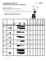
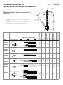
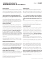
Figure 4. Reading Operating Specifications
Catalog
listing Contact block diagram
Nominal travels and related terminals
Contact Closed
Contact Open Diff. Travel
**Positive Opening to IEC 947-5-1
Operating force
max.
Disconnect force,
max.
Operating degrees,
max.
Operating degrees,
min.
Max. operate fre-
quency ops/min
GL**01A
GL**07A
SNAP-ACTION CONTACTS
SINGLE POLE
Zb
>
<
21-22
13-14
20°
56°**
12° Differential travel
9,7 N
[2.2 lb]
11,4 N
[2.6 lb]
0,85 M/S
[33.5 in/S]
8,5 mm/S
[0.33
in/S]
250
Ç Ç Ç Ç Ç Ç Ç Ç
Catalog
Listing
Code
Contact Block Diagram
Shows the circuit con-
figuration of the internal
contact block.
Operating Bar Charts
Show the state of the contacts relative to the
position of the actuator.
Operating Specifications
PRODUCT NOMENCLATURE
A2A
A2B
A1B
A1A
Side rotary,
fixed, 19 x 6
nylon roller
GL
Switch Type
A1A
Head/Actuator
C
D
Metal,
MIN-DIN
Plastic,
MIN-DIN
Body
C
3
2
1
CW rotation
only
CCW rotation
only
Lever to
right
NOTE: not all combinations of model code ar
e available.
Please contact your Honeywell pr
ovider/representative
for assistance.
E
Metal,
Pancake
A
B
1/2-14
NPT
PG 13.5
Conduit
A
C
20 mm
A4L
A5A
A4J
F
K8A
K8B
GLS Series
Global
Limit
Switch
4
Lever to
left
A5B
A1
A2
L
04
05
03
01
SPDT
snap action
SPDT, BBM
slow acting
SPDT, MBB
slow acting
DPST, 2NO
slow acting
07
24
06
DPST, 2NC
slow acting
DPDT, snap
action, Body E
SPDT, snap
action, gold cont.
32
DPDT, snap
action, gold cont.
Body E
34
35
33
SPDT, BBM
slow acting,
gold contacts
DPST, 2NO
slow acting,
gold contacts
SPDT, MBB
slow acting,
gold contacts
36
DPST, 2NC
slow acting,
gold contacts
01
Basic Switch
A9A
B
A1Y
A2Y
Side rotary,
fixed, 19 x 6
steel roller
Side rotary,
adjust., 19 x 6
nylon roller
Side rotary,
adjust., 19 x 6
steel roller
Side rotary,
adjust., 140 mm
aluminum rod
Side rotary,
adjust., 200 mm
aluminum rod
Side rotary,
offset, 19 x 6
nylon roller
Side rotary,
offset, 19 x 6
steel roller
Side rotary,
conveyor
lever
Top pin
plunger
Adj. top roller
lever, Ø27,3 x
5 POM roller
Cat whisker,
140 mm
Cat whisker,
190 mm
Side rotary,
fixed,
no roller
Side rotary,
adjustable,
no roller
Side rotary,
fixed, 50 x 10
rubber roller
Side rotary,
adj., 50 x 10
rubber roller
Modification Codes
A1A, A1B, A2A, A2B, A4J, A5B, A9
A
5
Lever to
mounting surf.
for
Actuator/Material C
6
Roller
perpendicular
to mtg. surf.
for
Actuator/Material D
6
Lever to
right, hinge
to left
D
C
Top roller
plunger
Top roller
lever
E7A
Wobble,
plastic stick
E7B
Wobble,
coil
E7D
Wobble,
cat whisker
K8C
Wobble,
cat whisker

8 sensing.honeywell.com
Installation Instructions for
MICRO SWITCH GLS Min-Din Limit Switches
ISSUE 10 81521
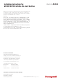
Figure 5. Head Code: A
Side Rotary Angular Operating Characteristics
Catalog
listing Contact block diagram
Nominal travels and related terminals
Contact Closed
Contact Open Diff. Travel
**Positive Opening to IEC 947-5-1
Operating torque
max.
Disconnect torque,
max.
Operating degrees,
max.
Operating degrees,
min.
Operating velocity,
min.
Operating velocity,
max.
Max. operate fre-
quency ops/min
GL**01A
GL**07A
Snap action
13
21
14
22
Zb
21-22
13-14
OP
FP
FP = 0°
OP = 26°
RP=14.5°
Total Travel = 70° min.
-4.4 15 mm 43,3
21-22
13-14
DT=9,8 mm
0,120
Nm
[1.1
in-lb]
0,140
Nm
[1.3
in-lb]
360° 10°
2,0
mm/s
200
mm/s
250
GL**03A
GL**33A
BBM, slow action
Zb
21
13
22
14
21-22
13-14
OP
FP
FP = 0°
OP = 26°
* = 36.5°
OP2 = 39°
Total Travel = 70° min.
-4.4 15 mm
25,9 mm
OP2
27,9
0,110
Nm
[1.0
in-lb]
0,160
Nm
[1.5
in-lb]
360° 10°
2,0
mm/s
200
mm/s
250
GL**04A
GL**34A
MBB, slow action
Zb
21
13
22
14
21-22
13-14
OT
OP2OPFP
FP = 0°
OP = 26°
* = 50.5°
OP2 = 39°
OT = 61° to 75°
-4.4 15 mm
40 mm
53.527.9
0,110
Nm
[1.0
in-lb]
0,170
Nm
[1.6
in-lb]
360° 10°
2,0
mm/s
200
mm/s
250
GL**05A
GL**35A
2 NO, slow action
13
23
14
24
2X
23-24
13-14
OT
OPFP
FP = 0°
OP = 39°
OT = 61° to 75°
-4.4 24,6 mm 53.5
0,110
Nm
[1.0
in-lb]
0,150
Nm
[1.4
in-lb]
360° 10°
2,0
mm/s
200
mm/s
250
GL**06A
GL**36A
2 NC, slow action
11
21
12
22
2Y
21-22
11-12
OTOP
FP
FP = 0°
OP = 26°
* = 46.5°
OT = 61° to 75°
-4.4 15 mm
36,5 mm
53.
5
0,110
Nm
[1.0
in-lb]
0,150
Nm
[1.4
in-lb]
360° 10°
2,0
mm/s
200
mm/s
250
GLE*24A
GLE*32A
2 NC/2 NO, snap
action
13
14
21
22
11
23
12
24
Za
Za
21-22
13-14
OP
FP
FP = 0°
DT = 8°
OP = 26°
* = 54°
-4.4 15 mm
43.3
23-24
11-12
21-22
13-14
23-24
11-12
DT=6,6 mm
RP=8,4 mm
RP = 18°
Total travel = 70° min.
0,165
Nm
[1.6
in-lb]
0,165
Nm
[1.6
in-lb]
10°
2,0
mm/s
200
mm/s
250
Notes:
• Free position, operate point, over travel and pre-travel all to EN 50047
• Operating characteristics apply to counter clockwise (CCW) and clock wise (CW) actuation
• Refer to page 6 for instructions on how to read operating characteristics and specifications
• Contact block terminal designation to EN 50013
• Tightening torque GLC/GLD: 0,5 Nm [4.4 in-lb] max.
• Tightening torque GLE: 0,339 Nm [3 in-lb] max.
OP2
OP
RP
OP +10°/-5°

Sensing and Internet of Things 9
Installation Instructions for
MICRO SWITCH GLS Min-Din Limit Switches
ISSUE 10 81521
Catalog
listing Contact block diagram
Nominal travels and related terminals
Contact Closed
Contact Open Diff. Travel
**Positive Opening to IEC 947-5-1
Operating force
max.
Disconnect force,
max.
Operating velocity,
max.
Operating velocity,
min.
Max. operate fre-
quency ops/min
GL**01B
GL**07B
Snap action
13
21
14
22
Zb
21-22
13-14
15 mm
16 mm
18 mm
21 mm
21-22
13-14
RP=18,9 mm
DT=0,9 mm
OT
max.
FP
16 N
[3.6 lb]
23 N
[5,2 lb]
100
mm/S
[3.9
in/S]
1,0 mm/S
[0.04
in/S]
250
GL**03B
GL**33B
BBM, slow action
Zb
21
13
22
14
21-22
13-14
15 mm
17 mm
18 mm
21 mm
OT max.
FP
17,2 mm
OP
14 N
[3,2 lb]
24 N
[5,4 lb]
100
mm/S
[3.9
in/S]
1,0 mm/S
[0.04
in/S]
250
GL**04B
GL**34B
MBB, slow action
Zb
21
13
22
14
21-22
13-14
15 mm
17 mm
18 mm
21 mm
OT max.
FP
16,2 mm
16 N
[3.6 lb]
27 N
[6.1 lb]
100
mm/S
[3.9
in/S]
1,0 mm/S
[0.04
in/S]
250
GL**05B
GL**35B
2 NO, slow action
13
23
14
24
2X
13-14
23-24
15 mm
17 mm
OP
21 mm
OT max.
FP
13 N
[2.9 lb]
23 N
[5.2 lb]
100
mm/S
[3.9
in/S]
1,0 mm/S
[0.04
in/S]
250
GL**06B
GL**36B
2 NC, slow action
11
21
12
22
2Y
21-22
11-12
15 mm
18 mm
OP
21 mm
OT max.
FP
16,5 mm
13 N
[2.9 lb]
23 N
[5.2 lb]
100
mm/S
[3.9
in/S]
1,0 mm/S
[0.04
in/S]
250
GLE*24B
GLE*32B
2 NC/2 NO, snap action
13
14
21
22
11
23
12
24
Za
Za
21-22
11-12
15 mm
18 mm
21 mm
OT max.
FP
RP=18,6 mm
13-14
23-24
DT=0,6 mm
13 N
[2.9 lb]
24 N
[5.4 lb]
100
mm/S
[3.9
in/S]
1,0 mm/S
[0.04
in/S]
250
Figure 6. Head Code: B
Pin Plunger Operating Characteristics
Notes:
• Free position, operate point, overtravel, and pretravel all to
EN 50047
• Refer to page 6 for instructions on how to read operating
characteristics and specifications
• Contact block terminal designation to EN 50013
0,9 [0.04]
Differ
ential travel
18,0 ±0,5 [0.71]
Operating point
21,0
[0.83]
Free position
15,0 max. [0.59 max.]
Overtravel

10 sensing.honeywell.com
Installation Instructions for
MICRO SWITCH GLS Min-Din Limit Switches
ISSUE 10 81521
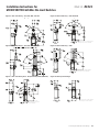
Figure 7. Head Code: C
Roller Plunger Operating Characteristics
Notes:
• Free position, operate point, overtravel, and pretravel all to
EN 50047
• Refer to page 6 for instructions on how to read operating
characteristics and specifications
• Contact block terminal designation to EN 50013
Catalog listing
Contact
block dia-
gram
Nominal travels and related
terminals
Contact Closed
Contact Open
Diff. Travel
**Positive Opening to IEC 947-5-1
Operating force max.
Disconnect force, max.
Operating velocity, max.
Operating velocity, min.
Max. operate frequency ops/min
GL**01C | GL**07C
Snap
action
13
21
14
22
Zb
21-22
13-14
5,3 mm
21-22
13-14
25 mm
OP 28 mm
31 mm
OT
max.
FP
RP=28,9 mm
21-22
13-14
26 mm
DT=0,9 mm
OT
21-22
13-14
RP=8,9 mm
DT=1,6 mm
FP
10,5 13,9 17,3
16 N [3.6 lb]
23 N [5,2 lb]
100 mm/S [3.9 in/S]
1,0 mm/S [0.04 in/S]
250
GL**03C | GL**33C
BBM, slow
action
Zb
21
13
22
14
21-22
13-14
5,3 mm
21-22
13-14
25 mm
28 mm
31 mm
OT max.
FP
27 mm
OT
FP
10,5
11,9
17,3
12,2
OP
27,2 mm
14 N [3.2 lb]
24 N [5.4 lb]
100 mm/S [3.9 in/S]
1,0 mm/S [0.04 in/S]
250
GL**04C | GL**34C
MBB, slow
action
Zb
21
13
22
14
21-22
13-14
5,3 mm
21-22
13-14
25 mm
28 mm
31 mm
OT max.
FP
27 mm
OT
FP
10,5
13,6
17,3
12,2
26,2 mm
16 N [3.6 lb]
27 N [6.1 lb]
100 mm/S [3.9 in/S]
1,0 mm/S [0.04 in/S]
250
Catalog listing
Contact
block dia-
gram
Nominal travels and related
terminals
Contact Closed
Contact Open
Diff. Travel
**Positive Opening to IEC 947-5-1
Operating force max.
Disconnect force, max.
Operating velocity, max.
Operating velocity, min.
Max. operate frequency ops/min
GL**05C | GL**35C
2 NO, slow
action
13
23
14
24
2X
23-24
13-14
5,3 mm
23-24
13-14
25 mm
31 mm
OT max.
FP
27 mm
OT FP
17,3
12,2
OP
OP
13 N [2.9 lb]
23 N [5.2 lb]
100 mm/S [3.9 in/S]
1,0 mm/S [0.04 in/S]
250
GL**06C | GL**36C
2 NC, slow
action
11
21
12
22
2Y
11-12
21-22
5,3 mm
11-12
21-22
25 mm
31 mm
OT max.
FP
28 mm
OT FP
17,
3
OP
26,5 mm
13,6
10,5
13 N [2.9 lb]
23 N [5.2 lb]
100 mm/S [3.9 in/S]
1,0 mm/S [0.04 in/S]
250
GLE*24C | GLE*32C
2 NC/2
NO, snap
action
13
14
21
22
11
23
12
24
Za
Za
11-12
21-22
5,3 mm
11-12
21-22
25 mm
31 mm
OT
max.
FP
28 mm
OT
FP
17,3
DT=0,6 mm
RP=28,6 mm
13,910,5
13-14
23-24
13-14
23-24
11-12
21-22
13-14
23-24
DT=1,0 mm
RP=9,5 mm
26
13 N [2.9 lb]
24 N [5.49 lb]
100 mm/S [3.9 in/S]
1,0 mm/S [0.04 in/S]
250
Differ
ential travel
28,0 ±1,0 [1.10]
Operating point
31,0
[1.22]
Free position
25,0 max. [0.98 max.]
Overtravel
RP

Sensing and Internet of Things 11
Installation Instructions for
MICRO SWITCH GLS Min-Din Limit Switches
ISSUE 10 81521
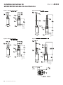
Figure 8. Head Code: D
Top Roller Lever Operating Characteristics
Notes:
• Free position, operate point, overtravel, and pretravel all to
EN 50047
• Refer to page 6 for instructions on how to read operating
characteristics and specifications
• Contact block terminal designation to EN 50013
Catalog listing
Contact
block dia-
gram
Nominal travels and related
terminals
Contact Closed
Contact Open
Diff. Travel
**Positive Opening to IEC 947-5-1
Operating force max.
Disconnect force, max.
Operating velocity, max.
Operating velocity, min.
Max. operate frequency ops/min
GL**01D | GL**07D
Snap
action
13
21
14
22
Zb
21-22
13-14
-0,3 mm
21-22
13-14
OP 35,8 mm
OP
RP=37,1 mm
21-22
13-14
DT=1,3 mm
OT
21-22
13-14
RP=6,7 mm
DT=3,6 mm
FP
10,4 18,3
23
10 N [2.2 lb]
13 N [3.0 lb]
100 mm/s
1,0 mm/s
250
GL**03D | GL**33D
BBM, slow
action
Zb
21
13
22
14
21-22
13-14
-0,3 mm
21-22
13-14
OP 35,8 mm
OP
OT
FP
10,4
13,6
23
OP
34,2
34,5
14,4
9 N [2.0 lb]
16 N [3.6 lb]
100 mm/s
1,0 mm/s
250
GL**04D | GL**34D
MBB, slow
action
Zb
21
13
22
14
21-22
13-14
-0,3 mm
21-22
13-14
35,8 mm
OP
OT
FP 10,4
17,6
23
34,2
32,9
14,4
10 N [2.2 lb]
17 N [3.8 lb]
100 mm/s
1,0 mm/s
250
Catalog listing
Contact
block dia-
gram
Nominal travels and related
terminals
Contact Closed
Contact Open
Diff. Travel
**Positive Opening to IEC 947-5-1
Operating force max.
Disconnect force, max.
Operating velocity, max.
Operating velocity, min.
Max. operate frequency ops/min
GL**05D | GL**35D
2 NO, slow
action
13
23
14
24
2X
13-14
23-24
-0,3 mm
13-14
23-24
OP
OT FP
23
34,2
14,4
OP
OT
FP
8 N [1.8 lb]
13 N [3.0 lb]
100 mm/s
1,0 mm/s
250
GL**06D | GL**36D
2 NC, slow
action
11
21
12
22
2Y
21-22
11-12
-0,3 mm
21-22
11-12
OP
OT
FP
23
35,8
10,4
OP
OT
FP
33,1
16,5
8 N [1.8 lb]
13 N [3.0 lb]
100 mm/s
1,0 mm/s
250
GLE*24D | GLE*32D
2 NC/
2 NO, snap
action
13
14
21
22
11
23
12
24
Za
Za
11-12
-0,3 mm
21-22
11-12
OP
OT
FP
23
OP=35,8
10,4 18,3
RP=36,7
DT=0,9
13-14
23-24
RP=8,0
DT=2,4
13-14
21-22
23-24
11-12
13-14
21-22
23-24
3,2 N [0.72 lb]
6,0 N [1.35 lb]
100 mm/s
1,0 mm/s
250
35,8 ±0,8 [1.41
]
Operating point
RP

12 sensing.honeywell.com
Installation Instructions for
MICRO SWITCH GLS Min-Din Limit Switches
ISSUE 10 81521
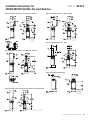
Figure 9. Head Code: K
Wobble Stick Angular Actuation Operating Char-
acteristics
Catalog
listing Contact block diagram
Nominal travels and related terminals
Contact Closed
Contact Open Diff. Travel
**Positive Opening to IEC 947-5-1
Operating torque
max.
Operating degrees,
max.
Operating degrees,
min.
Operating velocity,
max.
Operating velocity,
min.
Max. operate fre-
quency ops/min
GL**01K
GL**07K
Snap action
13
21
14
22
Zb
21-22
13-14
OT
max
.
OP
35°
21-22
13-14
0° 16°
RP=6°
DT=10°
FP
1,3 N
[0.29
lb]
360° 10°
13
rad/s
0.13
rad/s
100
GL**03K
GL**33K
BBM, slow action
Zb
21
13
22
14
21-22
13-14
OT
max.
OP
35°
0° 16° 27°
FP
1,1 N
[0.25
lb]
360° 10°
13
rad/s
0.13
rad/s
100
GL**04K
GL**34K
MBB, slow action
Zb
21
13
22
14
21-22
13-14
OT
max.
OP
35°
0° 16° 27°
FP
1,2 N
[0.27
lb]
360° 10°
13
rad/s
0.13
rad/s
100
GL**05K
GL**35K
2 NO, slow action
13
23
14
24
2X
13-14
23-24
OT
max.
OP
35°
0° 27°
FP
1,1 N
[0.25
lb]
360° 10°
13
rad/s
0.13
rad/s
100
GL**06K
GL**36K
2 NC, slow action
11
21
12
22
2Y
11-12
21-22
OT
max.
OP
35°
0° 16°
FP
1,1 N
[0.25
lb]
360° 10°
13
rad/s
0.13
rad/s
100
GLE*24K
GLE*32K
2 NC/2 NO, snap action
13
14
21
22
11
23
12
24
Za
Za
11-12
OP OT
max
.
FP
35°
RP=9°
DT=7°
13-14
21-22
23-24
11-12
13-14
21-22
23-24
16°0°
1,1 N
[0.25
lb]
360° 10°
13
rad/s
0.13
rad/s
100
Notes:
• Free position, operate point, over travel and pre-travel all to
EN 50047
• Refer to page 6 for instructions on how to read operating
characteristics and specifications
• Contact block terminal designation to EN 50013
16° ±5°
100,0
[3.94]
10°
DT
OP
OT
35°
max.

Sensing and Internet of Things 13
Installation Instructions for
MICRO SWITCH GLS Min-Din Limit Switches
ISSUE 10 81521
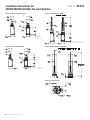
Figure 1. GLC Side Rotary • A1, A1A, A1B, and A1Y
Figure 2. GLC Side Rotary • A2, A2A, A2B, and A2Y
Figure 3. GLC Side Rotary Rod • A4J (140 mm) & A4L (200 mm)
3,5 mm [0.14 in] for PG 13,5 and
M20 conduit threads. 7,2 mm [0.28 in] for
0.5-14 NPT conduit threads.
Figure 4. GLC Side Rotary • A5A and A5B
3,5 mm [0.14 in] for PG 13,5 and M20 conduit threads.
7,2 mm [0.28 in] for 0.5-14 NPT conduit threads.
Figure 5. GLC Side Rotary • A9A
3,5 mm [0.14 in] for PG 13,5 and M20 conduit threads.
7,2 mm [0.28 in] for 0.5-14 NPT conduit threads.
Figure 6. GLC Top Pin Plunger
3,5 mm [0.14 in] for PG 13,5 and M20 conduit threads.
7,2 mm [0.28 in] for 0.5-14 NPT conduit threads.

14 sensing.honeywell.com
Installation Instructions for
MICRO SWITCH GLS Min-Din Limit Switches
ISSUE 10 81521
Figure 7. GLC Top Roller Plunger
3,5 mm [0.14 in]
for PG 13,5 and
M20 conduit
threads.
7,2 mm [0.28 in]
for 0.5-14 NPT
conduit threads.
Figure 8. GLC Top Roller Arm
3,5 mm [0.14 in]
for PG 13,5 and
M20 conduit threads.
7,2 mm [0.28 in] for
0.5-14 NPT conduit
threads.
Figure 9. GLC Wobble • E7B
3,5 mm [0.14 in]
for PG 13,5 and
M20 conduit threads.
7,2 mm [0.28 in] for
0.5-14 NPT conduit
threads.
Figure 10. GLC Wobble • K8A/K8B
or
or
3,5 mm [0.14 in]
for PG 13,5 and
M20 conduit threads.
7,2 mm [0.28 in] for
0.5-14 NPT conduit
threads.
Figure 11. GLC Conduit

Sensing and Internet of Things 15
Installation Instructions for
MICRO SWITCH GLS Min-Din Limit Switches
ISSUE 10 81521
Figure 12. GLD Side Rotary • A1, A1A, A1B, and A1Y
3,5 mm [0.14 in]
for PG 13,5 and
M20 conduit threads.
7,2 mm [0.28 in] for
0.5-14 NPT conduit
threads.
Figure 13. GLD Side Rotary • A2, A2A, A2B, and A2Y
Figure 14. GLD Side Rotary Rod • A4J (140 mm) & A4L (200 mm)
3,5 mm [0.14 in] for PG 13,5 and M20 conduit threads.
7,2 mm [0.28 in] for 0.5-14 NPT conduit threads.
Figure 15. GLD Side Rotary • A5A and A5B
3,5 mm [0.14 in]
for PG 13,5 and
M20 conduit threads.
7,2 mm [0.28 in] for
0.5-14 NPT conduit
threads.
Figure 16. GLD Side Rotary • A9A
3,5 mm [0.14 in]
for PG 13,5 and
M20 conduit threads.
7,2 mm [0.28 in] for
0.5-14 NPT conduit
threads.
Figure 17. GLD Top Pin Plunger
3,5 mm [0.14 in]
for PG 13,5 and
M20 conduit threads.
7,2 mm [0.28 in] for
0.5-14 NPT conduit
threads.

16 sensing.honeywell.com
Installation Instructions for
MICRO SWITCH GLS Min-Din Limit Switches
ISSUE 10 81521
Figure 18. GLD Top Roller Plunger
3,5 mm [0.14 in]
for PG 13,5 and M20
conduit threads.
7,2 mm [0.28 in] for
0.5-14 NPT conduit threads.
Figure 19. GLD Top Roller Arm
3,5 mm [0.14 in] for PG 13,5 and M20 conduit threads.
7,2 mm [0.28 in] for 0.5-14 NPT conduit threads.
Figure 20. GLD Wobble • E7B
3,5 mm [0.14 in] for PG 13,5 and M20 conduit threads.
7,2 mm [0.28 in] for 0.5-14 NPT conduit threads.
Figure 21. GLD Wobble • K8A/K8B
Figure 22. GLD Conduit

Sensing and Internet of Things 17
Installation Instructions for
MICRO SWITCH GLS Min-Din Limit Switches
ISSUE 10 81521
Figure 23. GLE Side Rotary • A1, A1A, A1B, and A1Y
Figure 24. GLE Side Rotary • A2, A2A, A2B, and A2Y
Figure 25. GLE Side Rotary • A4J and A4L
Figure 26. GLE Side Rotary • A5A and A5B
Figure 27. GLE Side Rotary • A9A
Figure 28. GLE Top Pin Plunger

18 sensing.honeywell.com
Installation Instructions for
MICRO SWITCH GLS Min-Din Limit Switches
ISSUE 10 81521
Figure 29. GLE Top Roller Plunger
Figure 30. GLE Top Roller Arm
Figure 31. GLE Wobble • E7B
Figure 32. GLE Wobble • K8A
Figure 33. GLE Conduit Adapter for 0.514 NPT

Sensing and Internet of Things 19
Installation Instructions for
MICRO SWITCH GLS Min-Din Limit Switches
ISSUE 10 81521
WARRANTY/REMEDY
Honeywell warrants goods of its manufacture as being free of defective
materials and faulty workmanship. Honeywell’s standard product war-
ranty applies unless agreed to otherwise by Honeywell in writing; please
refer to your order acknowledgement or consult your local sales office
for specific warranty details. If warranted goods are returned to Honey-
well during the period of coverage, Honeywell will repair or replace, at its
option, without charge those items it finds defective. The foregoing is
buyer’s sole remedy and is in lieu of all other warranties, expressed
or implied, including those of merchantability and fitness for a
particular purpose. In no event shall Honeywell be liable for conse-
quential, special, or indirect damages.
While Honeywell may provide application assistance personally,
through our literature and the Honeywell web site, it is up to the cus-
tomer to determine the suitability of the product in the application.
Specifications may change without notice. The information we supply
is believed to be accurate and reliable as of this printing. However, we
assume no responsibility for its use.
GARANZIA/RISARCIMENTO
Honeywell garantisce che i propri prodotti sono esenti da difetti nei
materiali e nella manodopera. Rimane valida la garanzia di prodotto
standard Honeywell, se non diversamente concordato dalla stessa per
iscritto. Fare riferimento alla ricevuta dell’ordine o rivolgersi all’ufficio
vendite della propria zona, per ulteriori dettagli sulla garanzia. Durante
il periodo di validità della garanzia, Honeywell provvederà alla riparaz-
ione o alla sostituzione, a sua discrezione e senza alcun addebito degli
articoli restituiti e riscontrati difettosi. Tale azione costituisce l’unico
risarcimento per l’acquirente e sostituisce tutte le altre garan-
zie, esplicite o implicite, incluse quelle della commerciabilità e
dell’idoneità ad uno scopo particolare. In nessun caso Honeywell è
da ritenersi responsabile per danni conseguenti, speciali o indiretti.
Honeywell fornisce assistenza in merito alle applicazioni tramite il
proprio personale, il proprio materiale informativo ed il proprio sito Web;
tuttavia è responsabilità del cliente verificare l’idoneità del prodotto
all’applicazione.
I dati tecnici sono soggetti a modifica senza alcun preavviso. Le in-
formazioni fornite nel presente documento sono da ritenere accurate
ed affidabili. Tuttavia, Honeywell non si assume alcuna responsabilità
in merito al loro impiego.
GARANTIE UND HAFTUNGSANSPRÜCHE
Honeywell garantiert für seine hergestellten Produkte fehlerfreies
Material und Qualitätsarbeit. Es gilt die durch Honeywell schriftlich
mitgeteilte StandardProduktgarantie von Honeywell. Informationen zu
Garantiedetails finden Sie auf Ihrer Auftragsbestätigung bzw. erhalten
Sie von Ihrer örtlichen Niederlassung. Wenn Produkte mit Garantie
innerhalb der Garantiefrist an Honeywell zurückgesendet werden,
ersetzt oder repariert Honeywell die als fehlerhaft angesehen Teile nach
eigenem Ermessen kostenlos. Das Vorangegangene gilt als einzige
Entschädigung des Käufers und ersetzt alle anderen ausdrückli-
chen oder stillschweigenden Garantien, einschließlich Qualitäts-
und Sachmängelhaftung. In keinem Fall haftet Honeywell für
mittelbare, indirekte oder Sondeschäden.
Obwohl Honeywell persönliche und schriftliche Anwendungshilfe sowie
Informationen über die Honeywell Website bietet, ist es die Entscheid-
ung des Kunden, ob das Produkt sich für die entsprechende Anwend-
ung eignet.
Änderungen der technischen Daten ohne Vorankündigung sind vorbe-
halten. Die hier gegebenen Informationen sind nach unserem Wissen
zum Zeitpunkt der Drucklegung korrekt. Wir übernehmen dennoch
keinerlei Verantwortung für deren Verwendung.
GARANTIE/RECOURS
Honeywell garantit que les articles de sa fabrication sont exempts
de défauts de pièces et main d’œuvre. La garantie standard sur les
produits Honeywell est d’application sauf indication contraire écrite et
approuvée par Honeywell. Veuillez vous reporter au récépissé de votre
commande ou consulter votre bureau de vente local pour obtenir des
détails spécifiques sur la garantie. Si les articles garantis sont retournés
à Honeywell pendant la période de couverture, Honeywell réparera ou
remplacera, à sa discrétion, gratuitement ceux qui auront été trouvés
défectueux. Ce qui précède constitue le seul recours de l’acheteur
et se substitue à toutes autres garanties, explicites ou implicites, y
compris celles relatives à la commercialisation ou la compatibilité
avec une application particulière. Honeywell ne peut être en aucun
cas tenu responsable de tout dommage indirect, spécial ou acces-
soire.
Bien que nous fournissions une assistance aux applications par le biais
de notre bibliographie et le site Web Honeywell, il appartient au client
de déterminer l’aptitude du produit pour son application.
Les caractéristiques techniques peuvent changer sans préavis. Les
informations que nous diffusons sont réputées précises et fiables au
moment de leur impression. Nous n’assumons cependant aucune
responsabilité pour leur usage.
CLAUSULA DE GARANTÍA
Honeywell garantiza que todos los productos que fabrica están libres
de defectos de mano de obra o materiales. La garantía del producto
estándar de Honeywell se aplica a menos que Honeywell haya acor-
dado lo contrario por escrito; consulte a su confirmación de orden o a
su oficina de ventas local para detalles específicos de garantía. Si se
devuelven productos con garantía a Honeywell durante el período de
cobertura, Honeywell los reparará o reemplazará, de manera opcio-
nal, si determina que están defectuosos. Esta cláusula de garantía
sustituye a cualquier otra garantía, ya sea explícita o implícita. En
ningún caso Honeywell será responsable por daños consecuentes,
especiales o indirectos.
Aunque Honeywell ofrece asistencia personal para las aplicaciones
por medio de sus publicaciones y páginas web, es el cliente quien debe
determinar la idoneidad del producto en la aplicación.
Las especificaciones pueden cambiar sin previo aviso. La información
suministrada es considerada correcta y fiable en el momento de esta
impresión. No obstante, no asumimos la responsabilidad por su uso.
GARANTIA/SOLUÇÕES
A Honeywell garante seus produtos contra defeitos de material e de
fabricação. A garantia padrão de produto da Honeywell se aplica a
menos que haja um acordo diferente por escrito com a Honeywell;
consulte a sua confirmação de encomenda ou consulte o escritório
de vendas local para obter detalhes específicos da garantia. Quando
produtos dentro do período de cobertura da garantia forem devolvidos
à Honeywell, esta se compromete a reparar ou substituir, de acordo
com a opção da empresa, por um novo aqueles produtos que consid-
erar defeituosos. O acima estipulado é a única solução oferecida ao
comprador e substitui quaisquer outras garantias, expressas ou im-
plícitas, inclusive garantias de comerciabilidade e adequação a um
fim específico. Em hipótese alguma a Honeywell deve ser respon-
sabilizada por danos conseqüenciais, especiais ou indiretos.
Embora a Honeywell proporcione assistência pessoal, através de lit-
eratura e de seu site na web, cabe ao cliente determinar qual produto é
mais adequado à sua aplicação.

Installation Instructions for
MICRO SWITCH GLS MinDin Limit Switches
ISSUE 10 81521
Especificações podem ser alteradas sem aviso prévio. Acreditamos que
as informações aqui contidas eram as mais precisas e confiáveis no
momento da impressão desta publicação. No entanto, não assumimos
qualquer responsabilidade pelo uso destas.
保证/补救
霍尼韦尔保证,本公司所制造的产品不存在任何有缺陷的材料和工艺上的缺
陷。如霍尼韦尔未另外以书面形式同意,则适用霍尼韦尔的标准产品保证;
请参阅订单确认书或咨询当地销售处了解具体保修细节。如果用户在保修期内
将产品退回公司,霍尼韦尔将负责免费维修或更换存在缺陷的零部件。上述条
款是购买人所能获得的唯一补救方法,并取代所有其他明示或暗指的保证,包
括有关针对某一特定目的的适销性和适用性的保证。霍尼韦尔对衍生性损害、
特殊损害与间接损害概不负责。
尽管我们可以派专人、通过我们的技术资料和霍尼韦尔网站等方式提供应用支
持,但确定产品在应用中是否适合则取决于用户自身。
技术规格若有改动,恕不另行通知。本文所提供的信息自印刷之日起均视为准
确、可靠。但是,我们不对本文的使用承担任何责任。
PK 8152110MLa | 10 | 04/19
© 2019 Honeywell International Inc. All rights reserved.
Honeywell Sensing and Internet of Things
9680 Old Bailes Road
Fort Mill, SC 29707
www.honeywell.com
For more information
Honeywell Sensing and Internet of
Things services its customers through a
worldwide network of sales offices and
distributors. For application assistance,
current specifications, pricing or the
nearest Authorized Distributor, visit
sensing.honeywell.com or call:
Asia Pacific +65 63552828
Europe +44 1698 481481
USA/Canada +18005376945
-
 1
1
-
 2
2
-
 3
3
-
 4
4
-
 5
5
-
 6
6
-
 7
7
-
 8
8
-
 9
9
-
 10
10
-
 11
11
-
 12
12
-
 13
13
-
 14
14
-
 15
15
-
 16
16
-
 17
17
-
 18
18
-
 19
19
-
 20
20


Honeywell PK 81521GLS Min-Din Global Limit Switches Installation guide
- Type
- Installation guide
- This manual is also suitable for
Ask a question and I''ll find the answer in the document
Finding information in a document is now easier with AI
in other languages
- italiano: Honeywell PK 81521GLS Min-Din Global Limit Switches Guida d'installazione
- français: Honeywell PK 81521GLS Min-Din Global Limit Switches Guide d'installation
- Deutsch: Honeywell PK 81521GLS Min-Din Global Limit Switches Installationsanleitung
- português: Honeywell PK 81521GLS Min-Din Global Limit Switches Guia de instalação
Related papers
-
Honeywell GLAA01C Operating instructions
-
-
-
-
-
-
-
Honeywell 12CX Installation And Service Instructions Manual
-
-
Other documents
-
RKI Instruments GD-K8A Owner's manual
-
Panasonic AM1 (NZ BASIC) User manual
-
Philips CP9934/01 Datasheet
-
Allen-Bradley 802T Installation guide
-
-
steute ES 13 WH Mounting And Wiring Instructions
-
-
Schneider Electric ALTIVAR 18 User manual
-
 Z-BEN D700 Series Installation guide
-
Acson 5WSS10AR Installation guide
