Page is loading ...

@crown
®
* System
®
Product Reference
MPX-6
™
Mixer-Router
ENABLEDSPI
LMP
+–+–+–+–+–
AUDIO
IN
6
+– +– +– +– +–
MAIN
CROWN BUS
AUX
CTRL
RS232 / RS422 / PA422
AUDIO
IN
5
AUDIO
IN
4
AUDIO
IN
3
AUDIO
IN
2
AUDIO
IN
1
120 VAC
60 Hz
20 W
SERIAL DATA LOOP
AUDIO
OUT
2
AUDIO
OUT
1
BUS
STACK
IN
MAIN BUS
STACK
IN
0
-5
-10
-12
5
10
15
21
ADD 25
FOR MIC
LMP
0
-5
-10
-12
5
10
15
21
ADD 25
FOR MIC
LMP
0
-5
-10
-12
5
10
15
21
ADD 25
FOR MIC
LMP
0
-5
-10
-12
5
10
15
21
ADD 25
FOR MIC
LMP
0
-5
-10
-12
5
10
15
21
ADD 25
FOR MIC
LMP
0
-5
-10
-12
5
10
15
21
ADD 25
FOR MIC
OUT IN
+
–
+
–
INPUT
GROUND
ONLY
IN
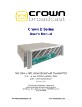
MPX-6 COMPUTER CONTROLLED MIXER-ROUTER
(Front Panel shown above, Rear Panel shown below)
OVERVIEW
What is an MPX-6?
The MPX-6 is a single rack space five
by one automatic mixer designed to be
configured with a computer and appro-
priate software. Once initially setup the
computer becomes optional. The key to
the MPX-6 operating as a stand alone
mixer is distributed intelligence
™
. In an
IQ System the brains of the system live
out in the system. This means the audio
system is not going to be lost even if the
computer or communication cables fail.
The MPX-6 is an ideal choice for appli-
cations where computerized manual
mixing or routing is desired and the au-
tomation of the SMX-6 or AMB-5 auto-
matic mixers is not required.
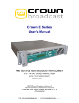
HARDWARE BLOCK DIAGRAM
Refer to the pictures of the front and rear
panels shown above and the block dia-
gram of the MPX-6 mixer on Page 2.
Audio Main Inputs:
Six balanced inputs with removable 3
pin barrier block. The preamp stage in-
cludes:
• M/L/P switches
set each input to
line level (L) with 0
dB gain, mic level
(M) with 25 dB ad-
ditional gain, or
phantom (P) which is 25 dB addi-
tional gain and +44 VDC phantom
power.
• A trim pot at each input allows for
prefade gain adjustment of –12 dB
to +21 dB gain after the M/L/P
switch.
There are two VCAs under processor
control at the output of each preamp.
One VCA controls the gain from input to
output mix 1 and the other VCA controls
gain from the input to output mix 2. The
net result is 12VCAs total.
Audio Stack Inputs:
Two inputs, one per output mix. Connec-
tions are via unbalanced RCA phono
jacks. These inputs are op-amp isolated.
There is no processor control of audio
coming into these inputs. The purpose
of the stack inputs is to allow construc-
tion of a wide mixer with more than six
inputs by taking the outputs of one mixer
and going into the stack inputs of a sec-
ond mixer. This means that main inputs
do not have to be used to expand the
effective size of the overall mixer.
Audio Main Outputs:
There are two summing
buses. Each summing
bus provides the out-
put mix for the corre-
sponding output chan-
nel. Op-amps buffer
the summing bus to the
output connection and balance the au-
dio output. The outputs are via 3 pin re-
movable barrier blocks.
Audio Bus Outputs:
In addition to the two main outputs, there
are also two bus outputs. Bus outputs 1
and 2 provide the same audio output as
main outputs 1 and 2. Op-amps buffer
the summing bus to the output connec-
tion and balance the audio output. What
makes the Bus Outputs different are re-
lays under processor control which may
be used to turn on or off the Bus Output
drive. 3 Pin removable barrier blocks are
used.
Aux Port:
The unit is equipped with a TB-3M type
mini-XLR port. This port may be used to
provide a control signal or sense a con-
trol signal. Pin 1 is ground reference. Pin
2 is output under processor control.
When on it provides 10 VDC at 16 ma.
When off it is open collector (high im-
pedance). Pin 3 is sensing input. +5 to
+30 VDC is sensed as a logic high. The
circuit floats, therefor tie to ground or TTL
source for definite high or low.
Indicators:
A Power light on the front panel indicates
the unit is powered. A DSPI data signal
presence indicator indicates communi-
cation.
Crown Bus Port:
The Crown Bus is a serial data loop
where components are connected into
the loop and one component serves as
system interface for all. This unit may
serve as a system interface or may sim-
ply operate as a component on a Crown
Bus data loop. Although the Crown Bus
may function on a variety of media,
Crown uses a two-wire 20 ma current
loop for input and output Crown Bus
connections. On this unit connections
are made via 4 pin removable barrier
block. Even if the unit is communicating
directly with a PC via its serial port, it
always functions in software as an ad-
dressable component on a Crown Bus
loop. The unit must have a valid loop
address. A valid address is:
• 1 to 250 set via 8 segment DIP
switch
• No other MPX on the same Crown
Bus data loop may have the same
address.
The Crown Bus is asynchronous with 8
data bits, 1 start bit, 1 stop bit, no par-
ity, and operates at 38400 baud. The
MPX is not a U-Code protocol compo-
nent.
Serial Port:
The serial port on this unit is a female
25 pin D-Shell. RS232 and RS422 are
supported with 8 Data bits, 1 start bit, 1
stop bit, no parity. Up to 19200 baud
supported. The serial port for the AMB
may be used for direct communication
with a PC such that the AMB serves as
interface:
+–
AUDIO
IN
1
LMP
0
-5
-10
-12
5
10
15
21
ADD 25
FOR MIC
+–+–
AUDIO
OUT
1
MAIN BUS
STACK
IN
MPX-6 Mixer (Page 1 of 3)

@crown
®
* System
®
Product Reference
INPUT 1
PRE-AMP
BALANCED
BUCHANAN
CONNECTOR
GAIN POT
(-12 to +21dB)
M/L/P SWITCH
P = +25dB/+44VDC
M = +25dB
L = 0 dB
VCA
1-1
VCA
1-2
RS232/RS422
DB25
POWER
SUPPLY
MEMORY
BATTERY
BACKUP
CROWN BUS
AUX PORT
3-PIN
MINI XLR
ENABLE
DSPI
12345678
123456
BAUD RATE
& PARITY
IQ ADDRESS
4-PIN
BUCHANAN
ACTIVE
BALANCE
OUTPUT
AMP
ACTIVE
BALANCE
OUTPUT
AMP
ACTIVE
BALANCE
OUTPUT
AMP
ACTIVE
BALANCE
OUTPUT
AMP
SUMMING
MIX BUS 1
SUMMING
MIX BUS 2
STACK INPUT 1
STACK INPUT 2
FROM
CPU
FROM
CPU
BUS 1
RELAY
BUS 1
RELAY
FROM
CPU
FROM
CPU
MAIN 1
OUTPUT
BALANCED
BUCHANAN
CONNECTOR
BUS 1
OUTPUT
BALANCED
BUCHANAN
CONNECTOR
MAIN 2
OUTPUT
BALANCED
BUCHANAN
CONNECTOR
BUS 2
OUTPUT
BALANCED
BUCHANAN
CONNECTOR
CPU
(MICRO-
PROCESSOR)
TO
VCAs
TO BUS
RELAYS
COMMUNICATION
STANDARD
INPUT 2
PRE-AMP
BALANCED
BUCHANAN
CONNECTOR
GAIN POT
(-12 to +21dB)
M/L/P SWITCH
P = +25dB/+44VDC
M = +25dB
L = 0 dB
VCA
2-1
VCA
2-2
FROM
CPU
FROM
CPU
INPUT 3
PRE-AMP
BALANCED
BUCHANAN
CONNECTOR
GAIN POT
(-12 to +21dB)
M/L/P SWITCH
P = +25dB/+44VDC
M = +25dB
L = 0 dB
VCA
3-1
VCA
3-2
FROM
CPU
FROM
CPU
INPUT 4
PRE-AMP
BALANCED
BUCHANAN
CONNECTOR
GAIN POT
(-12 to +21dB)
M/L/P SWITCH
P = +25dB/+44VDC
M = +25dB
L = 0 dB
VCA
4-1
VCA
4-2
FROM
CPU
FROM
CPU
INPUT 5
PRE-AMP
BALANCED
BUCHANAN
CONNECTOR
GAIN POT
(-12 to +21dB)
M/L/P SWITCH
P = +25dB/+44VDC
M = +25dB
L = 0 dB
VCA
5-1
VCA
5-2
FROM
CPU
FROM
CPU
INPUT 6
PRE-AMP
BALANCED
BUCHANAN
CONNECTOR
GAIN POT
(-12 to +21dB)
M/L/P SWITCH
P = +25dB/+44VDC
M = +25dB
L = 0 dB
VCA
6-1
VCA
6-2
FROM
CPU
FROM
CPU
MPX-6 Basic Block Diagram
(Page 2 of 3)

@crown
®
* System
®
Product Reference
MPX-6 Mixer (Page 3 of 3)
• May serve as interface for com-
ponents connected to the Crown
Bus.
• Components supported include
other MPX units, SMX-6 mixers,
AMB-5 mixers, PIP-AP, PIP-APM,
PIP-APS, all MRX matrixers, and the
White 4700 Series EQ.
• No support for U-Code protocol.
Setup Switches:
• The IQ Address is set by an 8 seg-
ment DIP switch. Valid address values
are 1 to 250 (0 and 251-255 are reserved
for system usage).
• RS232/422 Standard switch must be
configured appropriately for use of the
serial port.
• Baud is adjustable via DIP switch up
to 19200. This setting must be config-
ured properly for use of the serial port.
• Parity is set ON or OFF and ODD or
EVEN via DIP switch. Normally set to
OFF, this setting only applies to use of
the serial port.
Memory Backup:
The unit is equipped with a recharge-
able battery. The unit has 60 day
memory backup on full charge.
COMPUTERIZED FEATURES
DSPI:
The Data Signal Presence Indicator
(DSPI) light on the front panel flashes to
indicate data traffic addressed to or from
the unit. This light may be forced on from
software.
Aux Port:
The aux port on the mixer is used to send
or receive a control voltage. From soft-
ware you may turn the aux output on or
off. IQ software is also able to sense the
status of the aux input and is capable of
taking independent action based on a
sensed input.
Bus Output Relays:
Audio bus outputs are identical to their
respective main outputs in every way
except for the addition of software con-
trolled isolation relays.
VCA Gain Control:
The heart of the MPX is its functionality
as a mixer. Each of the six main inputs
may be routed to either or both outputs
by VCAs under processor control. The
VCAs offer a control range of –100 to
+25 dB.
MANUAL MIXING IN REAL TIME
All setup is accomplished with IQ soft-
ware from a PC. You may make changes
from software that affect VCA gain in real
time. Gain may also be manipulated in
real time from alternate control devices
such as a Drone or a third party control
device (Ex. AMX, Crestron, Interface
Controls, etc.). Once VCA gains are set
from the PC (or control device) the pro-
cessor maintains that gain structure un-
til it receives an instruction to change.
SYSTEM LEVEL INFORMATION
Communication:
In an IQ System the basic communica-
tion structure is based on the premise
that it must be able to support a PC be-
ing used with several IQ components.
The computer is connected to the IQ
System interface via RS232. The inter-
face converts the protocol from RS232
to Crown Bus media and back again. In
a small system or a single MPX system
the MPX itself may serve as the system
interface. The IQ-INT II, IQ-PSI, Drone,
SMX-6, AMB-5 and MPX-6 are all com-
ponents which may serve as a system
interface for an MPX-6. The Crown Bus
is a serial data loop carrier of IQ com-
mand protocol. Crown has implemented
it as a two wire twisted pair current loop
to allow for low cost long distance con-
nections. For very long loops (over 1000
feet) data repeaters (IQ-RPT) or fiber
optic cable may be used to connect
equipment rooms that are some dis-
tance apart. The Crown Bus itself does
not carry audio.
U-Code Protocol:
U-Code is new form of IQ command
protocol developed for enhanced new
product and third party product devel-
opment. At this time the MPX-6 firmware
is not written in U-Code. Although it may
be used in systems with U-Code prod-
ucts, the MPX-6 may not be used as
system interface for U-Code products.
Software:
Several IQ Software packages are avail-
able to communicate with an MPX-6.
Each unit is shipped with basic DOS
software which allows you to communi-
cate with the SMX-6, AMB-5, MPX-6,
and MRX Matrixer units. More advanced
software includes the Turbo or Sys-
Config software packages. Turbo is a
DOS program that includes powerful
graphics support and support of the full
IQ product line. Sys-Config is an ad-
vanced package which has security,
scheduling, alert reporting, and other
powerful features plus the power of
Turbo built in.
PC Requirements:
The computer you select for use with
your IQ System is very important. Exact
minimum requirement vary depending
on the software package being used,
but for the more advanced software your
machine should at least be a 486SX/33
with the following: 4 MB RAM, 16550
UART for the com port used by IQ, DOS
6.2, Mouse (with DOS driver, third but-
ton features supported). In most cases
Turbo software will operate as a DOS
application from Windows,
®
including
Windows 95.
®
SPECIFICATIONS
Maximum Input Level (Mic): +7 dBu.
Maximum Input Level (Line): +32 dBu.
Phantom Power: +44 VDC.
AC Power: 120/240 VAC 50/60 Hz.
Common Mode Rejection: 55 dB: 60 to 1 kHz
typical; 45 dB: 20 to 20 kHz.
Frequency Response: +0/-1 dB, 20 to 20 kHz.
THD: <0.05% at +4 dBm output; <0.15% at
+20 dBm output 20 to 20 kHz measured at
mic input with 40 dB gain.
Noise: Output noise all inputs off is –80dBu
(106 dB below rated output); output noise
with one line input at 0 dB is 80 dB; equiva-
lent input noise at mic input with 46 dB of
gain and 150 ohm source is –125 dBu. Note
that noise specs are typical, unweighted,
and 20 to 20 kHz.
Crosstalk: Adjacent inputs/outputs at 1 kHz
better than –80 dB; adjacent inputs/outputs
20 to 20 kHz better than –65 dB.
Guaranteed Excellence
@crown
Crown International, Inc.
Professional Audio Division
PO Box 1000
Elkhart, IN 46515-1000
Ph. 800-342-6939/219-294-8200
Fax. 219-294-8301
Trademark Notice:
Algo,
™
Distributed Intelligence,
™
and
MPX-6
™
are
trademarks,
Crown
®
and
IQ System
®
are regis-
tered trademarks of Crown International Inc.
/