Page is loading ...

iConverter GX/T2
Plug-in Module User Manual
Product Overview
The GX/T2 is a 10/100/1000BASE-T UTP to 100BASE-FX or 1000BASE-X modular ber media
converter that supports jumbo frames up to 10,240 bytes. The GX/T2 features Small Form Pluggable
(SFP) transceivers that support both 100BASE-FX and 1000BASE-X for interoperability with Fast
Ethernet and Gigabit ber equipment.
Installation Procedure
1) Congure DIP-switches
2) Install Module in Chassis and Connect Cables
3) Verify Operation
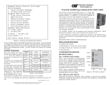
1) CONFIGURE DIP-SWITCHES
DIP-SWITCH BANK 1
The location of the DIP-switches is shown in Figure
1. The functions of DIP-switch Bank 1 are outlined
in Figure 2.
SW1 and SW2: BACKPLANE ENABLE
When these DIP-switches are in the “DS” position
(factory default), the Backplane Port of the GX/T2 is
isolated from the Ethernet Backplane on the chassis.
When these DIP-switches are in the “EN” position,
the Backplane Port is enabled. This allows Ethernet
Backplane connectivity to an adjacent module via the
chassis A/B Backplane Link depending on the switch
setting. Refer to the chassis user manual for detailed
information on the Ethernet Backplane.
SW3: L2CP Block
When this DIP-switch is in the default Down position, the module will forward all L2CP frames. When
the DIP-switch is in the Up position, the module will discard all L2CP frames.
SW4: Reserved
This DIP-switch is reserved and must be in the Down (default) position.
Switch Legend Function DOWN (Default) UP
SW1 A-DS/EN Backplane A Enable/Disable DS (Disable) EN (Enable)
SW3 B-DS/EN Backplane B Enable/Disable DS (Disable) EN (Enable)
SW3 L2CP L2CP Block Off (Forward) On (Discard)
SW4 - Reserved Off On
Figure 2: DIP-switch BANK 1 Denitions
DIP-SWITCH BANK 2
The functions of DIP-switch Bank 2 are outlined in Figure 3.
SW1: Port 1 “Auto/100”
This DIP-switch congures the speed of the transceiver installed in Port 1. If the DIP-switch is
in the Down “Auto” (default) position, the port detects the data rate of the transceiver installed
Page 1
and operates at 100M or 1G accordingly. If the DIP-switch is in the Up “100” position, the port is
expecting a 100M capable transceiver to be installed.
NOTE: SW1 is not available for xed ber models. The ber port is always set to 1000.
SW2: Port 2 “AN/Man”
This DIP-switch congures Port 2 for Auto Negotiation or Manual operation.
Switch Legend Function DOWN (Default) UP
SW1 Auto/100 Port 1 Speed and Duplex Auto 100
SW2 AN/Man Port 2 Negotiation Auto Manual
SW3 100/10 Port 2 Speed 100 10
SW4 FDX/HDX Port 2 Duplex FDX HDX
SW5 Mode 1
Asymmetrical Link Propagate
Port 1 to Port 2
Link Segment
Link Propagate
Port 1 to Port 2
SW6 Mode 2
Asymmetrical Link Propagate
Port 2 to Port 1
Link Segment
Link Propagate
Port 2 to Port 1
SW7 Off/On Pause Off On
SW8 On/Off MAC Learning On Off
Figure 3: DIP-switch Bank 2 Denitions
SW3 and SW4: Port 2 Speed “100/10” and Duplex “FDX/HDX”
See Figure 4 for conguring negotiation, duplex mode and speed.
SW2
AN/Man
SW3
100/10
SW4
FDX/HDX
RJ-45 Mode of Operation
AN 10 or 100 FDX or HDX
When set to auto-negotiation the following modes are advertised:
1000FDX, 1000HDX, 100FDX, 100HDX, 10FDX, 10HDX
Man 100 FDX The RJ-45 port is set to manual and is forced to 100FDX
Man 100 HDX The RJ-45 port is set to manual and is forced to 100HDX
Man 10 FDX The RJ-45 port is set to manual and is forced to 10FDX
Man 10 HDX The RJ-45 port is set to manual and is forced to 10HDX
Figure 4: Port Speed and Duplex Selection
SW5 and SW6: Link Modes “Mode 1” and “Mode 2”
These DIP-switches congure the link mode settings. It is recommended to have link modes
DOWN “Off” position (default) during the initial installation. After the circuit has been tested and
operational, congure the module for the desired mode.
Link Segment
In Link Segment mode, all ports operate independently. A loss of a receive link signal will only
affect the port detecting the loss of signal. All the other ports will continue to generate a link signal.
Link Propagate
In Link Propagate mode, the loss of a receive link signal will continue to propagate through to the
next port in the network causing the port to drop link.
Asymmetrical Link Propagate
In Asymmetrical Link Propagate mode, faults are propagated based on the port notation. Port 1 to
Port 2 notation indicates the direction the loss of link signal will propagate. A loss of receive link
on the ber optic Port 1 causes the UTP Port 2 to drop its link due to the propagated state (Port
1 to Port 2). The loss of link on the in the Port 1 to Port 2 direction. See Figure 5 for valid Link
Mode congurations.
Page 2

Page 3
SW5 SW6 Function
Down Down Link Segment
Down Up Link Propagate Port 2 to Port 1
Up Down Link Propagate Port 1 to Port 2
Up Up Link Propagate
Figure 5: Link Modes
SW7: Pause “Off/On”
The Pause DIP-switch sets the ow control functionality for all ports on the module, including pause
mode advertisement, pause functionality, and half duplex back pressure. When the DIP-switch is
in the Pause “On” position, ow control functionality is enabled. When this DIP-switch is in the
Pause “Off” position (factory default), ow control functionality is disabled.
If Pause is On and the port is in half duplex, then half duplex ow control is enabled. When a port is
in half duplex ow control it generates a back pressure signal when internal buffer resources are low.
If Pause is On and the port is in full duplex, then full duplex ow control is enabled. When a port is
in full duplex ow control and internal buffering resources are low, a pause frame is generated to
slow down the trafc ow to the port.
SW8: MAC Learning “On/Off”
When this DIP-switch is in the “On” position (factory default), all ports on the module will learn the
source MAC address of each received packet and store the address so packets destined for the
stored addresses can be forwarded to the appropriate interface on the module. When the DIP-switch
is in the “Off” position, learning is turned off and all received packets are forwarded to all ports.
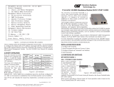
2) INSTALL MODULE IN CHASSIS AND CONNECT CABLES
Caution: Use proper ESD protection to reduce the risk of damage to your equipment.
a. Carefully slide the module into an open slot in the chassis. Align the module with the
installation guides and ensure that the module is rmly seated against the backplane. Secure
the module by fastening the front panel thumbscrew (push in and turn clockwise to tighten)
to the chassis front. Verify the “Pwr” LED is ON (indicating the chassis is powered).
b. When using a GX/T2 model with a SFP port, insert the SFP ber transceivers into the SFP
receptacles on the module.
NOTE: The release latch of the SFP transceiver must be in the closed (up) position
before insertion.
The GX/T2 module has the ability to detect the speed and automatically congure the port to
match the speed of Omnitron SFP transceivers. For non-Omnitron transceivers, congure
the port for the correct speed of the transceiver using SW1 of DIP-switch Bank 2.
c. Connect the appropriate multimode or single-mode ber cable to the ber port of the installed
module. It is important to ensure that the transmit (TX) is attached to the receive side of the
device at the other end and the receive (RX) is attached to the transmit side. Single-ber
(SF) transceivers operate in pairs. The TX wavelength must match the RX wavelength at
the other end and the RX wavelength must match the TX wavelength at the other end.
d. Connect the RJ-45 port via a Category 5 or better cable to a 10BASE-T, 100BASE-TX or
1000BASE-T Ethernet device (depending on the conguration of the port).
3) VERIFY OPERATION
Verify the correct LED is illuminated based on the conguration of the port. Figure 6 and 7 on the
next page indicates the operation of the port based on the illuminated LEDs. If the 100 LED is
illuminated, the port is operating at 100Mbps. If the 1000 LED is illuminated, the port is operating
at 1000Mbps and if the 100 and 1000 LEDs are illuminated, the port is operating at 10Mbps.
LED Function
“Legend”
Color OFF State ON/Blinking State
Power
“PWR”
Green No power Module has power
P1 Link Activity
1
“100”
Green/
Amber
Port not linked at 100M
Solid Green: Port linked at 100M
Blinking Green: Data activity
Blinking Amber: Port is operating at
100M and receiving FEFI
P1 Link Activity
“1000”
Green/
Amber
Port not linked at 1000M
Solid Green: Port linked at 1000M
Blinking Green: Data activity
Blinking Amber: Port is operating at
1000M and receiving a remote fault
P1 Link Activity
1
“100” and “1000”
Green Port not linked at 10M
Solid Green: Port linked at 10M
Blinking Green: Data activity
P1 Duplex
“P1 FDX”
Green
Port is congured for half
duplex per DIP-switch or
resolved by auto-negotiation
Solid Green: Port is congured for
full duplex operation per DIP-switch or
resolved by auto-negotiation
P1 SFP DMMI Alarm
1
“P1 Stat”
Green/
Amber
Installed transceiver does not
support digital diagnostics or
no transceiver installed
Solid Green: Installed transceiver
supports digital diagnostics and no alarm
detected
Solid Amber: Installed transceiver has
detected an alarm
P2 Negotiation Mode
“P2 AN”
Green
Port is congured for Manual
operation
Solid Green: Port is congured for Auto-
negotiation
Blinking Green: Port is congured for
auto-negotiation but has not completed
the process with attached link partner
P2 Link Activity
“100”
Green/
Amber
Port not linked at 100M
Solid Green: Port linked at 100M
Blinking Green: Data activity
Blinking Amber: Port receiving a remote
fault at 100Mbps
P2 Link Activity
“1000”
Green/
Amber
Port not linked at 1000M
Solid Green: Port linked at 1000M
Blinking Green: Data activity
Blinking Amber: Port receiving a remote
fault at 1000Mbps
P2 Link Activity
“100” and “1000”
Green Port not linked at 10M
Solid Green: Port linked at 10M
Blinking Green: Data activity
P2 Duplex
“P2 FDX”
Green
Port is congured for half
duplex per DIP-switch or
resolved by auto-negotiation
Solid Green: Port is congured for
full duplex operation per DIP-switch or
resolved by auto-negotiation
Figure 6: LED Indicators
1
LEDs are not installed on the xed ber models
040-8520N-002C 10/15
Omnitron Systems Technology 38 Tesla, Irvine, CA 92618
949.250.6510 tel * 949.250.6514 fax * www.omnitron-systems.com
©2015 Omnitron Systems Technology, Inc. iConverter is a registered trademark of Omnitron Systems Technology, Inc.
Trademarks are owned by their respective companies. Specications subject to change without notice. All rights reserved.
/