Page is loading ...

© Freescale Semiconductor, Inc., 2009 - 2014. All rights reserved.
Freescale Semiconductor
User’s Guide
Document Number: KT33937UG
Rev. 2.0, 8/2014
KIT33937AEKEVBE Evaluation Board
Contents
1 Important Notice . . . . . . . . . . . . . . . . . . . . . . . . . . . . . . . . . . . . . . . . . . . . . . . . . . . . . . . . . . . . . . . . . . . . . . . . . . . . . . . . . . . . . 2
2 Introduction and Setup . . . . . . . . . . . . . . . . . . . . . . . . . . . . . . . . . . . . . . . . . . . . . . . . . . . . . . . . . . . . . . . . . . . . . . . . . . . . . . . . 3
3 Operational Description . . . . . . . . . . . . . . . . . . . . . . . . . . . . . . . . . . . . . . . . . . . . . . . . . . . . . . . . . . . . . . . . . . . . . . . . . . . . . . . 6
4 Pin Description . . . . . . . . . . . . . . . . . . . . . . . . . . . . . . . . . . . . . . . . . . . . . . . . . . . . . . . . . . . . . . . . . . . . . . . . . . . . . . . . . . . . . . 6
5 Design Considerations . . . . . . . . . . . . . . . . . . . . . . . . . . . . . . . . . . . . . . . . . . . . . . . . . . . . . . . . . . . . . . . . . . . . . . . . . . . . . . . 12
6 KIT33937AEKEVBE Evaluation Board Schematics . . . . . . . . . . . . . . . . . . . . . . . . . . . . . . . . . . . . . . . . . . . . . . . . . . . . . . . . . 13
7 Bill of Materials . . . . . . . . . . . . . . . . . . . . . . . . . . . . . . . . . . . . . . . . . . . . . . . . . . . . . . . . . . . . . . . . . . . . . . . . . . . . . . . . . . . . . 18
8 Board Layouts . . . . . . . . . . . . . . . . . . . . . . . . . . . . . . . . . . . . . . . . . . . . . . . . . . . . . . . . . . . . . . . . . . . . . . . . . . . . . . . . . . . . . 20
9 References . . . . . . . . . . . . . . . . . . . . . . . . . . . . . . . . . . . . . . . . . . . . . . . . . . . . . . . . . . . . . . . . . . . . . . . . . . . . . . . . . . . . . . . . 22
10 Revision History . . . . . . . . . . . . . . . . . . . . . . . . . . . . . . . . . . . . . . . . . . . . . . . . . . . . . . . . . . . . . . . . . . . . . . . . . . . . . . . . . . . . 23

KT33937UG, Rev. 2.0
2 Freescale Semiconductor
Important Notice
1 Important Notice
Freescale provides the enclosed product(s) under the following conditions:
This evaluation kit is intended for use of ENGINEERING DEVELOPMENT OR EVALUATION PURPOSES ONLY. It is provided as a
sample IC pre-soldered to a printed circuit board to make it easier to access inputs, outputs, and supply terminals. This EVB may be
used with any development system or other source of I/O signals by simply connecting it to the host MCU or computer board via
off-the-shelf cables. This EVB is not a Reference Design and is not intended to represent a final design recommendation for any
particular application. Final device in an application is heavily dependent on proper printed circuit board layout and heat sinking design
as well as attention to supply filtering, transient suppression, and I/O signal quality.
The goods provided may not be complete in terms of required design, marketing, and or manufacturing related protective considerations,
including product safety measures typically found in the end product incorporating the goods. Due to the open construction of the
product, it is the user's responsibility to take any and all appropriate precautions with regard to electrostatic discharge. In order to
minimize risks associated with the customers applications, adequate design and operating safeguards must be provided by the
customer to minimize inherent or procedural hazards. For any safety concerns, contact Freescale sales and technical support services.
Should this evaluation kit not meet the specifications indicated in the kit, it may be returned within 30 days from the date of delivery and
will be replaced by a new kit.
Freescale reserves the right to make changes without further notice to any products herein. Freescale makes no warranty,
representation or guarantee regarding the suitability of its products for any particular purpose, nor does Freescale assume any liability
arising out of the application or use of any product or circuit, and specifically disclaims any and all liability, including without limitation
consequential or incidental damages. “Typical” parameters can and do vary in different applications and actual performance may vary
over time. All operating parameters, including “Typical”, must be validated for each customer application by customer’s technical experts.
Freescale does not convey any license under its patent rights nor the rights of others. Freescale products are not designed, intended,
or authorized for use as components in systems intended for surgical implant into the body, or other applications intended to support or
sustain life, or for any other application in which the failure of the Freescale product could create a situation where personal injury or
death may occur.
Should the Buyer purchase or use Freescale products for any such unintended or unauthorized application, the Buyer shall indemnify
and hold Freescale and its officers, employees, subsidiaries, affiliates, and distributors harmless against all claims, costs, damages, and
expenses, and reasonable attorney fees arising out of, directly or indirectly, any claim of personal injury or death associated with such
unintended or unauthorized use, even if such claim alleges that Freescale was negligent regarding the design or manufacture of the
part.Freescale™ and the Freescale logo are trademarks of Freescale Semiconductor, Inc. All other product or service names are the
property of their respective owners.
© Freescale Semiconductor, Inc. 2014

KT33937UG, Rev. 2.0
Freescale Semiconductor 3
Introduction and Setup
2 Introduction and Setup
2.1 Introduction
This User’s Manual describes the features, options and connections of the KIT33937AEKEVBE Evaluation Board. Freescale’s
KIT33937AEKEVBE Evaluation Board is a low-voltage power stage that is an integral part of Freescale’s embedded motion control
series of development tools. For additional information on Freescale’s Motion Control Development Tools go to
www.freescale.com/motor control In combination with one of the embedded motion control series, control evaluation boards, it provides
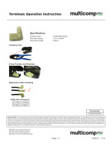
a ready-made software development platform for small brushless DC motors among others. An illustration of the system configurations
is shown in
Figure 1.
The KIT33937AEKEVBE Evaluation Board has the following features:
• Connecting the Evaluation Board via a UNI-3 connector
• SPI communication between the 33937A Driver and a microcontroller
• DC-Bus current and voltage sensing
• Over-current detection with adjustable current maximum value
• Optional input supply voltage of 8 - 42 Volts
•3.3 V, 5.0 V, and 12 V voltage generation on the boards
• Output 3-phase motor connector
Figure 1 depicts the board layout with descriptions of the components.
Figure 1. System Configuration
CONTROLLER
BOARD
MC33927
MOTOR
WORKSTATION
MCF523xEC, MPC555, 56800/E HYBRID CONTROLLER, S12Exx MICROCONTROLLER
OPTIONAL FEEDBACK
EVALUATION BOARD
KIT33937AEKEVBE
*
*

KT33937UG, Rev. 2.0
4 Freescale Semiconductor
Introduction and Setup
2.2 About this Manual
Key items can be found in the following locations in this manual:
• Setup instructions are found in section Setup Guide.
• Pin-by-pin descriptions are contained in Table 2 up to Table 10.
• For those interested in the reference design aspects of the board’s circuitry, a description is provided in Design Considerations
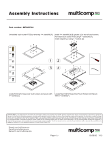
Figure 2. KIT33937AEKEVBE Evaluation Board
2.3 Disposing of Old Appliances
The KIT33937AEKEVBE Evaluation Board must be disposed of in compliance with current local waste disposal regulations. Disposing
of old appliances should be done by a qualified company.
2.4 Terms and Acronyms
BLDC Brushless DC
EVB Evaluation Board
Hall sensor Sensor whose output changes based on changes in magnetic flux. Used to measure motor position.
PWM Pulse width modulation
UNI-3 User-to-Network Interface

KT33937UG, Rev. 2.0
Freescale Semiconductor 5
Introduction and Setup
2.5 Warnings
The KIT33937AEKEVBE Evaluation Board includes components which can reach temperatures hot enough to cause burns. To facilitate
safe operation, the 8.0 to 42
V input power should come from a DC laboratory power supply that is current limited to no more than
4.5 amps.
The user should be aware of:
• Before moving scope probes, making connections, etc., it is generally advisable to power down the DC voltage supply.
• Operating in lab setups that have grounded tables and/or chairs should be avoided.
• It is also advisable to wear safety glasses, avoiding wearing ties and jewelry, use shields, and operate by personnel trained in
power electronics lab techniques are also advisable.
2.6 Setup Guide
Setup and connections for the KIT33937AEKEVBE Evaluation Board are straightforward. The KIT33937AEKEVBE Evaluation Board
connects to a Freescale embedded motion control series control board via a 40-pin ribbon cable. The motor’s power leads plug into
output Motor connector (J100).
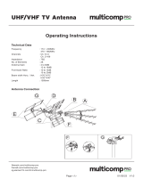
Figure 3 depicts a completed setup.
Follow these steps to set up the board:
1. Plug one end of the 40-pin ribbon cable supplied with Freescale’s embedded motion control series control boards into input UNI-3
connector (J200), located at the edge of the KIT33937AEKEVBE Evaluation Board.
2. Plug the free end of the cable into the control board’s 40-pin connector.
3. Connect a 8.0 to 42 VDC power supply either to the power jack J7 labelled “8-42 V”, or to the connector J1.
4. If protection features are desired, set the overcurrent detection comparator trimmer, R114, to 2.75 V. This value limits DC bus
current to 3.0
amps.
5. Apply power to the KIT33937AEKEVBE Evaluation Board. The yellow power-on LED is lit when power is present. Note that the
KIT33937AEKEVBE Evaluation Board doesn’t power the control board, so the control board must be powered by means of an
external 12
VDC power supply to run a complete system.
Figure 3. KIT33937AEKEVBE Evaluation Board Setup
MOTOR
MC33297
12-VOLT
POWER SUPPLY
CONTROL BOARD
40-PIN
RIBBON CABLE
J1
Evaluation Board
J4
8-42 Vdc
POWER SUPPLY
33937A
Evaluation
Board

KT33937UG, Rev. 2.0
6 Freescale Semiconductor
Operational Description
3 Operational Description
3.1 Introduction
Freescale’s embedded motion control series KIT33937AEKEVBE Evaluation Board is a 8.0 to 42 VDC, 4.5 amp, surface-mounted
power stage. In combination with one of the embedded motion control series control boards, it provides a software development platform
that allows algorithms to be written and tested without the need to design and build a power stage for small brushless DC motors,
amongst others. It supports algorithms that use Hall sensors, a Quadrature encoder, and Zero-cross signals for sensor-less control.
The KIT33937AEKEVBE Evaluation Board has an overcurrent protection that is implemented on the 33937A driver and is independent
of the control board. Current measuring circuitry is set up from -4.5 to 4.5
amps full scale. In a 25 °C ambient operation at up to 4.5 A,
continuous RMS output current is within the board’s thermal limits.
The control interface is created via the 40-pin ribbon cable connector J200. Pin assignments for the input connector are shown in
Figure 4. Power connections to the motor are made on output connector J100. Phase A, B, and C are labelled on the board. Power
requirements are met by a single external 8.0 to 42 V, 5 .0 A power supply. Two connectors, labelled J7 and J1, are provided for the
power supply. Both are located in one corner of the board.
For design information, see Design Considerations.
3.2 Electrical Characteristics
The electrical characteristics in Table 1 apply to operation at 25 C and a 12 VDC power supply voltage.
4 Pin Description
4.1 Connectors and Test Points
Inputs and outputs are located on connectors and test points. Pin descriptions for each of these connectors and the test points are
identified in following information.
4.2 40-Pin Connector J200
Signal inputs and outputs are grouped together on the 40-pin connector J200, located on the top of the board. Pin assignments and
descriptions are shown in Figure 4. Pin descriptions are listed in Table 2.
Table 1. Electrical Characteristics
Characteristic Symbol Min. Typ. Max. Units
Power Supply Voltage V
DC
8.0 12 42 V
Quiescent Current I
CC
— 10.4 — mA
Logic 1 Input Voltage V
IH
2.1 — — V
Logic 0 Input Voltage V
IL
— — 0.9 V
Analog Output Range V
OUT
0.0 — 3.3 V
Bus Current Sense Voltage I
SENSE
— 366 — mV/A
Bus Voltage Sense Voltage V
BUS
— 69 — mV/V
Power MOSFET On Resistance R
DS(ON)
— 45 55 mOhm
Continuous Output Current I
D
— — 4.5 A
Pulsed Output Current I
DM
— — 30 A
Total Power Dissipation P
DISS
— — 2.4 W

KT33937UG, Rev. 2.0
Freescale Semiconductor 7
Pin Description
Note that some J200 signals have a different usage than in the standard UNI-3 Interface. This is due to the need for the SPI
communication 33937A driver and the driver control signals - Reset, Enable, and Overcurrent. Some pins on J200 are not connected,
in comparison to the UNI-3 standard. Changed pin assignments are shown in
Table 2
For more information refer to Table 9
Table 2. Changed Pins’ Descriptions
Pin # UNI-3 Standard J12 Connector
19 +15 V_A / +12 V_A +12 V
20 -15 V_A / -12 V_A Not connected
23 I_sense_A SPI_CSB
24 I_sense_B SPI_SO
25 I_sense_C SPI_SI
26 Temp_sense SPI_SCLK
29 Brake_control DRV_INT
30 Serial_con DRV_RST
31 PFC_PWM DRV_EN
32 PFC_enable OC_IRQ
33 PFC_z_c Not connected
38 BEMF_sense_A Not connected
39 BEMF_sense_B Not connected
40 BEMF_sense_C Not connected

KT33937UG, Rev. 2.0
8 Freescale Semiconductor
Pin Description
Figure 4. 40-Pin Input Connector J200
40
39
38
37
36
35
34
33
32
31
30
29
28
27
26
25
24
23
22
21
20
19
18
17
16
15
14
13
12
11
10
9
8
7
6
5
4
3
2
1
NC
NC
NC
Shielding
Zero_cross_C
Zero_cross_B
Zero_cross_A
NCc
OC_IRQ
DRV_EN
DRV_RST
INT
Shielding
Reserved
SCLK
SI
SO
CSB
I_sense_DCB
V_sense_DCB
NC
+12V_A
GNDA
GNDA
+5V_A
+5V_D
+5V_D
GND
GND
PWM_CB
Shielding
PWM_CT
Shielding
PWM_BB
Shielding
PWM_BT
Shielding
PWM_AB
Shielding
PWM_AT
SCHEMATIC VIEW
J200
CON/40
2
4
6
8
10
12
14
16
18
20
22
24
26
28
30
32
34
36
38
40
1
3
5
7
9
11
13
15
17
19
21
23
25
27
29
31
33
35
37
39
Shielding
Shielding
Shielding
Shielding
Shielding
GND
+5V_D
+5V_A
GNDA
-12V_A
I_sense_DCB
SO
SCLK
Shielding_A
DRV_RST
OC_IRQ
Zero_cross_A
Zero_cross_C
NC
NC
PWM_AT
PWM_AB
PWM_BT
PWM_BB
PWM_CT
PWM_CB
GND
+5V_D
GNDA
+12V_A
V_sense_DCB
CSB
SI
Reserved
INT
DRV_EN
Reserved
Zero_cross_A
Shielding_A
NC
PHYSICAL VIEW
B

KT33937UG, Rev. 2.0
Freescale Semiconductor 9
Pin Description
NOTE
* Pins which are connected differently than in the User Network Interface, Version 3.0 (UNI-3)
standard.
Table 3. Connector J200 Signal Description
Pin # Signal Name Description
1 PWM_AT
PWM_AT is the gate drive signal for the top bridge of phase A. A logic high at input connector J10 turns on the phase
A top switch
3 PWM_AB
PWM_AT is the gate drive signal for the bottom bridge of phase A. A logic high at input connector J10 turns on the
phase A bottom switch
5 PWM_BT
PWM_BT is the gate drive signal for the top bridge of phase B. A logic high at input connector J10 turns on the phase
B top switch
7 PWM_BB
PWM_AT is the gate drive signal for the bottom bridge of phase B. A logic high at input connector J10 turns on the
phase B bottom switch
9 PWM_CT
PWM_AT is the gate drive signal for the top bridge of phase C. A logic high at input connector J10 turns on the phase
C top switch
11 PWM_CB
PWM_AT is the gate drive signal for the bottom bridge of phase C. A logic high at input connector J10 turns on the
phase C bottom switch
12 GND Digital power supply ground
13 GND Digital power supply ground
17 AGND Analog power supply ground
18 AGND Analog power supply ground
19 * +12V_A Analog power supply
20 * NC Not connected
21 V_SENSE_DCB V_sense is an analog sense signal that measures dc bus voltage
22 I_SENSE_DCB I_sense is an analog sense signal that measures dc bus current
23 * CSB Chip select signal of the SPI communication
24 * SO Output signal of the SPI communication
25 * SI Input signal of the SPI communication
26 * SCLK Clock signal of the SPI communication
27 NC Not Connected
28 Shielding_A Analog Shielding. Must be grounded on the power stage side only!
29 * DRV_ INT 33937A driver Interrupt signal
30 * DRV_RST 33937A driver Reset signal
31 * DRV_EN 33937A driver Enable signal
32 * OC_IRQ 33937A driver Overcurrent signal
33 * NC Not connected
34 Zero_cross_A Digital input. Phase A Back-EMF zero crossing
35 Zero_cross_B Digital input. Phase B Back-EMF zero crossing
36 Zero_cross_C Digital input. Phase C Back-EMF zero crossing
37 Shielding_A Analog Shielding. Must be grounded on the power stage side only!
38 * NC Not connected
39 * NC Not connected
40 * NC Not connected

KT33937UG, Rev. 2.0
10 Freescale Semiconductor
Pin Description
4.3 SPI Communication Connectors J201 and J202
SPI signal inputs from the control board are grouped onto the 6-pin connector J201. Two signals (CSB, SO) are also available on the
2-pin connector J202. Pin descriptions are listed in Table 4 and Table 5.
The output signal SO from the 33937A driver is connected to the control board’s input signal SI, and likewise the input signal SI from
the 33937A driver is connected to the control board’s output signal SO.
4.4 3-Pin Motor Connector J100
Power outputs to the motor are located on the 3-pin connector J100, labeled “Motor Connector”. Pin descriptions are listed in Table 6.
4.5 Power Supply Connectors J1 and J7
Two connectors, labelled J1 and J7, are provided for the 8.0 to 42 VDC power supply. Both connectors are used for power supply input,
and are located in one corner of the board. The J7 connector is a 2.1
mm power jack for plug-in type dc power supply connections, the
J1 connector is a two-wire connector. The power supply should be able to deliver at least 3.0
amps.
4.6 Connectors J2 - J6
One-pin connectors J2 - J6 provide easy access to voltages available on the board. Connector descriptions are listed in Table 7.
Table 4. Connector J201 Signal Description
Pin # Signal Name Description
1 NC Not Connected
2 GND Digital power supply ground
3 CSB Chip select signal
4 SCLK Clock signal
5 SO Output signal
6 SI Input signal
Table 5. Connector J202 Signal Description
Pin # Signal Name Description
1 SO Output Signal
2 CSB Chip Select signal
Table 6. Connector J100 Signal Description
Pin # Signal Name Description
1 Phase_A Supplies power to motor phase A.
2 Phase_B Supplies power to motor phase B.
3 Phase_C Supplies power to motor phase C.
Table 7. Connectors J3-J6 Signal Description
Connector # Signal Name Description
J2 V_BATT Power supply voltage
J3 +3.3V_A Analog power supply
J4 GND Power supply ground
J5 +5V Digital power supply
J6 +12V Digital power supply

KT33937UG, Rev. 2.0
Freescale Semiconductor 11
Pin Description
4.7 Connectors J101 - J109
One-pin connectors J101 - J109 provide connections to the additional operational amplifier U100B (MC33502D) and three inverters
U101D-F (74HC04). Pin descriptions are listed in
Table 8.
4.8 Jumpers JP203 - JP206 for SPI Communication Selection
The jumpers JP203 - JP206 are used for SPI communication connector selection. The selection of signals is listed in Table 9.
4.9 Test points
Six test points provide easy access to the DC-Bus current and voltage sensing signals. They are listed in Table 10 along with their
descriptions and locations.
Table 8. Connectors J101 - J109 Signal Description
Connector # Signal Name Description
J101 AMPi+ op. amplifier non-invert input
J102 AMPi- op. amplifier invert input
J103 AMPo op. amplifier output
J104 NEG1i invertor 1 input
J105 NEG1o invertor 2 output
J106 NEG2i invertor 2 input
J107 NEG2o invertor 2 output
J108 NEG3i invertor 3 input
J109 NEG3o invertor 3 output
Table 9. Jumpers JP1 - JP3 Selection
Jumper
Name
Position Comment for SPI communication
J203 1 2 For CSB signal where the UNI-3 connector is not selected
J203 1-2 For CSB signal where the UNI-3 connector is selected
J204 1 2 For SO signal where the UNI-3 connector is not selected
J204 1-2 For SO signal where the UNI-3 connector is selected
J205 1 2 For SI signal where the UNI-3 connector is not selected
J205 1-2 For SI signal where the UNI-3 connector is selected
J206 1 2 For SCLK signal where the UNI-3 connector is not selected
J206 1-2 For SCLK signal where the UNI-3 connector is selected
Table 10. Test points
Test point no. Signal Name Locations
TP100 +1.65 Ref middle side of the board
TP101 OC_TH below IC U102
TP102 VDCB below connector J200
TP103 I_DCB+ right side of the resistor R100
TP104 IDCB- left side of the resistor R100
TP105 IDCB below connector J200
Position 1-2 Position 1 2

KT33937UG, Rev. 2.0
12 Freescale Semiconductor
Design Considerations
5 Design Considerations
5.1 Overview
From a systems point of view, the KIT33937AEKEVBE Evaluation Board fits into an architecture that is designed for code development.
In addition to the hardware that is needed to run a motor, a variety of feedback signals that facilitate control algorithm development are
provided. Input PWM signals from a control board process the 3-phase FET pre-driver 33937A. The description of the pre-driver is
contained in
3-Phase FET Pre-driver 33937A.
The KIT33937AEKEVBE Evaluation Board power output stage is a complementary MOS field effect transistor (MOSFET) 3-phase
bridge, capable of supplying and sensing 4.5
amps of continuous current. Feedback signals include bus voltage and the bus current.
Descriptions of each of these blocks are contained in 3-Phase Driver, and in Bus Voltage and Current Feedback.
5.2 3-Phase FET Pre-driver 33937A
The 3-Phase FET Pre-driver (33937A) is a FET pre-driver for 3-phase motor control and similar applications. The IC uses Freescale's
SMARTMOS technology. The IC contains 3 high-side FET pre-drivers and 3 low-side pre-driver. Three external bootstrap capacitors
provide gate charge to the high-side FETs.
The IC contains internal registers to control the various operating parameters, modes and interrupt characteristics.These commands
are sent and the status is read via 8-bit SPI commands. The IC will use the last 8 bits in a SPI transfer, so devices can be daisy-chained.
The return value from a SPI command is obtained via the SPI port on the subsequent command. It is in the SPI communication for the
next command that the response is delivered.
The IC also contains the high speed amplifier for ground current sensing, and the overcurrent comparator for overcurrent detection. For
more information on the pre-driver, refer to
References.
5.3 3-Phase Driver
The output stage is configured as a 3-phase driver with complementary MOSFET output transistors. It is simplified considerably by dual
integrated gate drivers, each having one inverting and one non-inverting driver. A simplified schematic showing one phase is illustrated
in
Figure 9.
One of the most important design decisions in a motor drive is the selection of the gate drive impedance for the output transistors. In
Figure 9, resistors R101 (51 ), R102 (51 ), and diode D100 determine gate drive impedance for the upper half-bridge transistor. A
similar network is used on the lower half-bridge. These networks set the turn-on gate drive impedance to approximately 100 and the
turn-off gate drive impedance at approximately 50
. These values produce transition times of approximately 60 ns. Transition times of
this length represent a carefully weighed compromise between power dissipation and noise generation. Generally speaking, transition
times longer than 250
ns tend to get power hungry at non-audible PWM rates; and transition times under 50 ns create di/dtfs so large
that proper operation is difficult to achieve. The 33937A EVB is designed with switching times at the lower end of this range to minimize
power dissipation.
5.4 Bus Voltage and Current Feedback
Feedback signals proportional to bus voltage and bus current are provided by the circuitry shown in Figure 8. Bus voltage is scaled down
by a voltage divider consisting of R115 (47 kohms), R118 (1.8 kohms), and R120 (3.6 kohms). The values are chosen such that a 48-volt
maximum bus voltage corresponds to a 3.3 volt maximum analog-to-digital (A/D) input.
Bus current is sampled by resistor R100, shown in Figure 9, and amplified by the 33937A driver. This circuit provides a voltage output
suitable for sampling with A/D inputs.
The gain is given by:
A = R117 / R121 (resistors are shown in Figure 8)
The output voltage is shifted up by 1.65 V, to accommodate both positive and negative current swings. A 180 mV voltage drop across
the shunt resistor corresponds to a measured current range of 4.5 A and to a voltage range from 0 to 3.3 V.
The overcurrent comparator, implemented on the 33937A driver, is adjusted by the trimmer R114 (shown in Figure 7), where a 2.75 V
setting for the overcurrent detection comparator produces a 3.0 A current limit.

KT33937UG, Rev. 2.0
Freescale Semiconductor 13
KIT33937AEKEVBE Evaluation Board Schematics
6 KIT33937AEKEVBE Evaluation Board Schematics
Figure 5. Power Supply
GND
+5V
+5V
GNDA
+3.3V_A
GND
+5V
GNDA GNDA GNDA GNDA GNDA
+3.3V
+5V
GND
+3.3V
+3.3V_A
GNDGNDGNDGND
GND_LSFET
+3.3V_A
VDD
+3.3V
+5V
+12V
GND
GND
GND
GNDGND
GNDGNDGND
GNDGND
GND
+12V
GND
+12V
GND
GNDA
+5V_A
+5V_A
GND
DCB_POS
DCB_POS
DCB_NEG
+3.3V
VDD
+3.3V_A
GND_LSFET
+5V
DCB_POS
DCB_POS
+12V
GNDA
GND
+5V_A
Range 8V - 42V
+2.5V
Current flows
when >40V
== DCB_NEG
12V/100mA Power Supply for UNI-3
Supply Voltage +5V Voltage Generation
+3.3V Voltage Generation
+3.3V_A Voltage Generation
Pover ON LED
Power Supply
L2
1mH
L2
1mH
SW
1
BST
2
RCL
3
RTN
4
FB
5
RON
6
VCC
7
VIN
8
U1
LM5007
U1
LM5007
1
J6
+12V
J6
+12V
+
C16
47uF/6.3V
+
C16
47uF/6.3V
R4
100k
R4
100k
1
2
3
J7
PWR Jack
8-42V J7
PWR Jack
8-42V
1
J5
+5V
J5
+5V
SGND
1
VBST
2
SW_H
3
VIN
4
BURST_EN
5
VC
6
VFB
7
SGND
8
SGND
9
SS
10
SHDN
11
VBIAS
12
VOUT
13
PWRGND
14
SW_L
15
SGND
16
EXPOSED_PAD
17
G
18
G
19
G
20
G
21
U4
LT3433IFE
U4
LT3433IFE
C3 100nF/16VC3 100nF/16V
R2
3k
R2
3k
D7
BAS16HT1
D7
BAS16HT1
R5
3k
R5
3k
C4 100nF/16VC4 100nF/16V
C7
100nF/100V
C7
100nF/100V
+
C18
1uF
100V
+
C18
1uF
100V
L3
TDK TH/220uH
DO3316P-224
L3
TDK TH/220uH
DO3316P-224
D6
MBRA120ET3
D6
MBRA120ET3
C20
100nF
16V
C20
100nF
16V
C8
100nF/50V
C8
100nF/50V
1
2
J1
CON/2screws
J1
CON/2screws
D5
BAS16HT1
D5
BAS16HT1
ANODE CATHODE
D4
MBRA160T3
D4
MBRA160T3
L1
TDK TH/100uH
L1
TDK TH/100uH
C5 100nF/16VC5 100nF/16V
C24
330pF
10V
C24
330pF
10V
TP2
+12V
TP2
+12V
R8
174k-1%
R8
174k-1%
1
J4
GND
J4
GND
C22
10nF
10V
C22
10nF
10V
Vin
1
Gnd
2
CE
3
Vout
5
U2
MC78PC33NTR
U2
MC78PC33NTR
C25
1nF
10V
C25
1nF
10V
1
J2
V_BATT
J2
V_BATT
1
J3
+3.3V_A
J3
+3.3V_A
+
C9
22uF/20V
+
C9
22uF/20V
C1
10nF/50V
C1
10nF/50V
C23
0.1uF
10V
C23
0.1uF
10V
VIN
3
VOUT
2
VOUT
4
GND
1
U3
MC33269ST-3.3T3
U3
MC33269ST-3.3T3
C10
100nF
C10
100nF
LED_ON1
YELLOW
LED_ON1
YELLOW
C19
100nF
100V
C19
100nF
100V
R6
68k
R6
68k
D3 SM/1N4001D3 SM/1N4001
R7
20k-1%
R7
20k-1%
R3 200kR3 200k
D2 MBR0520LT3D2 MBR0520LT3
+
C6
22uF/100V
+
C6
22uF/100V
TP1
+5V_A
TP1
+5V_A
+
C13
47uF/6.3V
+
C13
47uF/6.3V
+
C21
47uF
25V
+
C21
47uF
25V
+
C2 33uF/16V
+
C2 33uF/16V
GC1
Ground_Connection
GC1
Ground_Connection
+
C12
10uF/6.3V
+
C12
10uF/6.3V
C14
100nF
C14
100nF
TS1
BZW06-40
TS1
BZW06-40
C11
100nF
C11
100nF
D1
MBRD660CT
D1
MBRD660CT
C15
100nF
C15
100nF
+
C26
1uF
100V
+
C26
1uF
100V
R1
330R
R1
330R
C17
1uF 20V
C17
1uF 20V

KT33937UG, Rev. 2.0
14 Freescale Semiconductor
KIT33937AEKEVBE Evaluation Board Schematics
Figure 6. UNI-3 Connector
ZC_A
ZC_C
ZC_B
PWM_AT
PWM_CT
PWM_BB
PWM_BT
PWM_AB
PWM_CB
SI
SCLK
SO
SO
CSB
CSB
INT
DRV_EN
/DRV_RST
OC_IRQ
CSB SO SI SCLK
+5V_A
+5V
+12V
GND
GND
GNDA
GNDA
GNDA
+12V
+5V_A
GND
GNDA
GND_LSFET
+3.3V_A
VDD
+3.3V
+5V
V_DCB
I_DCB
+12V
+5V_A
GNDA
GND
+3.3V
VDD
+3.3V_A
GND_LSFET
+5V
SPI
+5V_D
+5V_D
GND
GND
GNDA
GNDA
Ctrl6/PWM_CB
Shielding_A
Ctrl4/PWM_BB
Ctrl3/PWM_BT
Ctrl2/PWM_AB
Brake_control
Zero_cross_C
BEMF_sense_A
Serial_Con
I_sense_A
V_sense_DCB
Shielding_A
I_sense_DCB
Ctrl5/PWM_CT
Shielding_D
PFC_PWM
Ctrl1/PWM_AT
BEMF_sense_C
I_sense_B
Shielding_D
I_sense_C
+15V_A/+12V_A
Shielding_D
Shielding_D
Shielding_D
Zero_cross_B
Zero_cross_A
BEMF_sense_B
UNI-3 Connector
PFC_enable
PFC_z_c
Reserved
Temp_sense
-15V_A/-12V_A
+5V_A
According to UNI-3 spec.
Optional SPI Connection when
the separate 5in-line-pin or
6-double-line-pin is unusable
Zero cross pins - if
application run wished
without external HS
CPU....DRV
------- ------
MOSI....SO
MISO....SI
Place the conns close to J200 (for ctrl board counterparts):
UNI-3pin1 towards SPI1pin1 & J201/J202 inline as shown
Compatibility Connections:
p5-SS...CSB-2(J202)/-3(J201)
p4-MOSI...SO-1(J202)/-5(J201)
p3-MISO...SI-6(J201)
p2-SPSCK...SCLK-4(J201)
p1-GND-2(J201)
1
2
J205
SSel3
J205
SSel3
1
2
J203
SSel1
J203
SSel1
12
34
56
J201
SPI1
J201
SPI1
1
2
J204
SSel2
J204
SSel2
1
2
3
4
5
6
7
8
9
10
11
12
13
14
15
16
17
18
19
20
21
22
23
24
25
26
27
28
29
30
31
32
33
34
35
36
37
38
39
40
J200
UNI-3
J200
UNI-3
1
2
J206
SSel4
J206
SSel4
C202
12nF
C202
12nF
R201
100R
R201
100R
1
2
J202
SPI2
J202
SPI2
C201
12nF
C201
12nF
R202
100R
R202
100R

KT33937UG, Rev. 2.0
Freescale Semiconductor 15
KIT33937AEKEVBE Evaluation Board Schematics
Figure 7. 33937A Driver
AMP_N
AMP_P
AMP_OUT
SCLK
SI
CSB
SO
OC_IRQ
DR V_E N
/D R V _ R S T
INT
ZC_A
ZC_B
ZC_C
PWM_AB
PWM_BB
PWM_CB
PWM_AT
PWM_BT
PWM_CT
+5V
VDD
+5V
VDD
GND_LSFET
GND_LSFET
GND_LSFET
DCB_POS
GND
GND
GND
GND
GND
GND
GND
GND
GND
GND
+12V
+5V _A
GND
GNDA
GND_LSFET
+3. 3V _A
VDD
+3. 3V
+5V
PA_HS_G
PA_LS_G
PB_HS_G
PB_LS_G
PC_HS_G
PC_LS_G
PH_C
PH_B
PH_A
+12V
+5V _A
GNDA
GND
+3. 3V
VDD
+3. 3V _A
GND_LSFET
+5V
Place as close as
pos s ible to the pins .
Decoupling capacitor
Place as close as possible
to VDD pin of U100
Place as close as
pos s ible to the pins .
J106
NEG 2i
J106
NEG 2i
1
C111
470nF/6.3V
C111
470nF/6.3V
U102U102
MC33937A
PhaseA
1
PGND for QPUMP
2
ENABLE1
3
ENABLE2
4
RESETB
5
N/C
6
PUMP
7
VPUMP(12V)
8
VSUP(42V)
9
PhaseB
10
PhaseC
11
nP A_HS
12
PA_LS
13
VDD
14
nP B _HS
15
PB_LS
16
INT
17
CSB
18
SI
19
SCLK
20
SO
21
PC_LS
22
nP C _HS
23
AMP_OUT
24
AMP_N
25
AMP_P
26
OC_Out
27
OC_TH
28
VSS
29
GND0
30
GND1
31
VLS_CAP
32
N/C
33
PC_LS_S
34
PC_LS_G
35
PC_HS_S
36
PC_HS_G
37
PC_BOOTSTRAP
38
PB_LS_S
39
PB_LS_G
40
PB_HS_S
41
PB_HS_G
42
PB_BOOTS TR AP
43
PA_LS_S
44
PA_LS_G
45
PA_HS_S
46
PA_HS_G
47
PA_BOOTS TR AP
48
N/C
49
N/C
50
VLS
51
N/C
52
N/C
53
VPWR
54
C108
150nF/50V
C108
150nF/50V
+
C101
60V
2.2uF
+
C101
60V
2.2uF
R 125
10k
R 125
10k
U101C
74HC 04D
U101C
74HC 04D
5 6
C106
150nF/50V
C106
150nF/50V
C107
150nF/50V
C107
150nF/50V
C112
100n/6.3V
C112
100n/6.3V
VCC
GND
U101A
74HC 04D
VCC
GND
U101A
74HC 04D
1 2
7 14
TP101
OC_TH
TP101
OC_TH
J109
NEG 3o
J109
NEG 3o
1
C109
25V
100nF
C109
25V
100nF
R 127
10k
R 127
10k
R 124 10kR 124 10k
J107
NEG 2o
J107
NEG 2o
1
C105
25V
100nF
C105
25V
100nF
J104
NEG 1i
J104
NEG 1i
1
J105
NEG 1o
J105
NEG 1o
1
R 126
10k
R 126
10k
J108
NEG 3i
J108
NEG 3i
1
U101F
74HC 04D
U101F
74HC 04D
1213
+
C104
2.2uF/25V
+
C104
2.2uF/25V
U101E
74HC 04D
U101E
74HC 04D
1011
C102
60V
1nF
C102
60V
1nF
+
C110
2.2uF/25V
+
C110
2.2uF/25V
U101D
74HC 04D
U101D
74HC 04D
89
R 114
10k
R 114
10k
1
2
3
U101B
74HC 04D
U101B
74HC 04D
3 4
C103
100nF/6.3V
C103
100nF/6.3V

KT33937UG, Rev. 2.0
16 Freescale Semiconductor
KIT33937AEKEVBE Evaluation Board Schematics
Figure 8. DC-Bus Voltage & Current Sensing
AMP_N
AMP_PI_DCBUS_POS
AMP_OUT
I_DCBUS_NEG
+3.3V_A
GNDA
GNDA
GNDA
GNDA
+3.3V_A
+3.3V_A
V_DCB
DCB_POS
DCB_NEG
I_DCB
DC-Bus Voltage & Current Sensing
DC Bus Current Sensing
DC Bus Voltage Sensing
3.30V @ 48V
0~3.3V @ -4.5 ~ 4.5A
OpAmp is within
3PP-A
R115
47k-1%
R115
47k-1%
J102
AMPi-
J102
AMPi-
1
R122 1.2k-1%R122 1.2k-1%
+
-
U100A
MC33502D
+
-
U100A
MC33502D
1
2
3
4 8
R116
10k-1%
R116
10k-1%
R129 10kR129 10k
R123 11k-1%R123 11k-1%
C113
100nF
C113
100nF
TP104
I_DCB-
TP104
I_DCB-
R120
3.6k-1%
R120
3.6k-1%
D107
MBRA160T3
D107
MBRA160T3
R117
11k-1%
R117
11k-1%
C100
10n/6.3V
C100
10n/6.3V
J103
AMPo
J103
AMPo
1
R121 1.2k-1%R121 1.2k-1%
TP102
VDCB
TP102
VDCB
R128
10k
R128
10k
TP103
I_DCB+
TP103
I_DCB+
TP105
IDCB
TP105
IDCB
+
-
U103B
MC33502D
+
-
U103B
MC33502D
7
6
5
D106
MBRA160T3
D106
MBRA160T3
J101
AMPi+
J101
AMPi+
1
R119
10k-1%
R119
10k-1%
TP100
+1.65ref
TP100
+1.65ref
R118
1.8k-1%
R118
1.8k-1%

KT33937UG, Rev. 2.0
Freescale Semiconductor 17
KIT33937AEKEVBE Evaluation Board Schematics
Figure 9. 3-Phase N-MOS Bridge
I_DCBUS_NEG
I_DCBUS_POS
GND_LSFET
PA_HS_G
PA_LS_G
PB_HS_G
PB_LS_G
PC_HS_G
PC_LS_G
PH_CPH_BPH_A
DCB_POS
DCB_NEG
PH_A
PH_B
PH_C
Create the junctions as
close to the resistor
R100 as possible.
3-Phase N-MOS Bridge
40mV/1A
3-ph. Motor Connector
3-pin Molex 39-26-3030 (mating with 26-11-2033)
Tycoelectronic: 640387-3 / Farnell 1453026
- pin 1: Phase A (brown)
- pin 2: Phase B (red)
- pin 3: Phase C (orange)
3
4
6
5
Q104-2
Si4946EY
Q104-2
Si4946EY
1
2
3
J100
3-ph. Motor
J100
3-ph. Motor
R108
51R
R108
51R
R111
51R
R111
51R
D105
MBRM140T3
D105
MBRM140T3
3
4
6
5
Q105-2
Si4946EY
Q105-2
Si4946EY
D103
MBRM140T3
D103
MBRM140T3
D101
MBRM140T3
D101
MBRM140T3
R104
51R
R104
51R
R109
51R
R109
51R
R107
51R
R107
51R
R105
51R
R105
51R
1
2
7
8
Q102-1
Si4946EY
Q102-1
Si4946EY
1 2
R100
0.040-1%
R100
0.040-1%
D104
MBRM140T3
D104
MBRM140T3
R110
51R
R110
51R
1
2
7
8
Q100-1
Si4946EY
Q100-1
Si4946EY
R101
51R
R101
51R
R102
51R
R102
51R
R112
51R
R112
51R
D102
MBRM140T3
D102
MBRM140T3
D100
MBRM140T3
D100
MBRM140T3
1
2
7
8
Q101-1
Si4946EY
Q101-1
Si4946EY
R103
51R
R103
51R
R106
51R
R106
51R
3
4
6
5
Q103-2
Si4946EY
Q103-2
Si4946EY

KT33937UG, Rev. 2.0
18 Freescale Semiconductor
Bill of Materials
7 Bill of Materials
Table 11. Bill of Materials
Qty. Reference Part Value Description Mfg. Mfg. Part No.
1 C1 10 nF/50 V Ceramic capacitor, 0805, 10 nF AVX 08055G103KAT1A
1 C2 22 F/ 16 V Ceramic capacitor, 1206, 22 F AVX 1206YD226KAT1A
3 C3, C4, C5 100 nF/ 25 V Ceramic capacitor, 0805, 100 nF AVX 08053G104KAT1A
1 C6 22 F/ 100 V
Electrolytic Capacitor
8.0 mm, 22 F/100 V
Jamicon SKR220M2AFBB
1 C7 100 nF/ 100 V Ceramic capacitor, 0805, 100 nF AVX 08051C104KAT1A
1 C8 100 nF/ 50 V Ceramic capacitor, 0805, 100 nF AVX 08055C104KAT1A
1 C9 22 F/ 16 V Ceramic Capacitor, 1206, 22 F/16 V AVX 1206YD226KAT1A
12
C10, C11, C14, C15, C19,
C20, C23, C103, C105,
C109, C112, C113
100 nF/50 V Ceramic capacitor, 0805, 100 nF AVX 08055C104KAT1A
1 C12 10 F/ 6.3 V Ceramic Capacitor, 1206, 10 F/6.3 V AVX 1206ZC106KAT1A
2 C13, C16 47 F/ 6.3 V Tantal Capacitor, 1206, 47 F/6.3 V AVX 12066D476KAT1A
1 C17 1.0 F/ 10 V Ceramic capacitor, 0805, 1.0 F AVX 0805ZG105ZAT1A
2 C18, C26 1.0 F/ 50 V Ceramic capacitor, 1206, 1.0 F TDK C3216X5R1H105K
1 C21 47 F/ 16 V Ceramic capacitor, 1210, 2x 22 F/16 TDK C3225X5R1C226M
1 C22 10 nF/ 50 V Ceramic capacitor, 0805, 10 nF AVX 08055G103ZAT1A
1 C24 330 pF/ 100 V Ceramic capacitor, 0805, 330 pF AVX 08055G331ZAT1A
2 C25, C102 10 nF/50 V Ceramic capacitor, 0805, 10 nF AVX 08055G102ZAT1A
1 C101 2.2 F/ 63 V Electrolytic Capacitor, 5mm, 2.2 F/ V Jamicon SKR2R2M1JFBB
2 C104, C110 2.2 F/ 25 V Ceramic Capacitor, 1206, 2.2 F/25 V AVX 12065C225KAT1A
3 C106, C107, C108 150 nF/50 V Ceramic capacitor, 0805, 150 nF AVX 08055C154KAT1A
2 C201, C202 12 nF/50 V Ceramic capacitor, 0805, 12 nF AVX 08055G120ZAT1A
1 D1 MBRD660CT Power Rectifiers ONSEMI MBRD660CTG
1 D2 MBR0520LT1 Shottky Rectifier ONSEMI MBR0520LT1G
1 D3 SM/1N4001 Standard Rectifier ONSEMI 1N4001
3 D4, D106, D107 MBRA160T3 Shottky Rectifier ONSEMI MBRA160T3G
2 D5, D7 BAS16HT1 Switching Diode ONSEMI BAS16HT1G
1 D6 MBRA120ET3 Shottky Power Rectifier ONSEMI MBRA120ET3G
6
D100, D101, D102, D103,
D104, D105
MBRM140T3 Shottky Power Rectifier ONSEMI MBRM140T3G
1 J1 CON/2 screws 2-pin connector PTR Mess Technik AR500/2
14
J2, J3, J4, J5, J6, J101,
J102, J103, J104, J105,
J106, J107, J108, J109
EXP. HEADER 1-Way Header MOLEX 22-28-4020
1 J7 PWR Jack Power Jack type connector 2.5 mm CUI stack PJ-002A
1 J100 3-ph. Motor 3-Way Header MOLEX 39-26-3030
1 J200 UNI-3 Header 40 pins breakway connector Fisher Elektronik ASLG40G
6
J201, J202, J203, J204,
J205, J206
EXP. HEADER 2-Way Header MOLEX 22-28-4020
1 LED_ON1 YELLOW 0805 LED diode yellow
Chicago Miniature
Lamp INC
7012x13
1 L1 TH / 100mH Inductor TDK TSL0709 -101KR66-PF
1 L2 1mH Inductor TDK SP0508-102KR19-PF

KT33937UG, Rev. 2.0
Freescale Semiconductor 19
Bill of Materials
3 L3 TH / 220mH Inductor TDK TSL0709 -221KR44-PF
3 Q100, Q101, Q102 SI4946BEY DUAL N-channel MOSFET VISHAY Si4946BEY-T1--E3
1 R1 330R Resistor 330 , 5%, 0805 Multicomp MC 0.1W 0805 5% 330R
2 R2, R5 3.0 k Resistor 3.0 k, 5%, 0805 Multicomp MC 0.1W 0805 5% 3k
1 R3 200 k Resistor 200 k, 5%, 0805 Multicomp MC 0.1W 0805 5% 200k
1 R4 100 k Resistor 100 km, 5%, 0805 Multicomp MC 0.1W 0805 5% 100k
1 R6 68 k Resistor 68 k, 5%, 0805 Multicomp MC 0.1W 0805 5% 68k
1 R7 18 k-1% Resistor 18 k, 1%, 0805 Multicomp MC 0.1W 0805 1% 18k
1 R8 160 k-1% Resistor 160 k, 1%, 0805 Multicomp MC 0.1W 0805 1% 160k
1 R100 0.040-1% Resistor 0.04 , 1%, Vishay LVR03R0400FE1231
12
R101, R102, R103, R104,
R105, R106, R107, R108,
R109, R110, R111, R112
51R Resistor 51 , 5%, 0805 Multicomp MC 0.1W 0805 5% 51R
6
R124, R125, R126,
R127, R128, R129
10 k Resistor 10 k, 5%, 0805 Multicomp MC 0.1W 0805 5% 10k
1 R114 10 k Trimmer Vishay ST-4EG-103
1 R115 47 k -1% Resistor 47 k, 1%, 0805 Multicomp MC 0.1W 0805 1% 47k
2 R116, R119 10 k - 1% Resistor 10 k, 1%, 0805 Multicomp MC 0.1W 0805 1% 10k
2 R117, R123 11 k - 1% Resistor 11 k, 1%, 0805 Multicomp MC 0.1W 0805 1% 11k
1 R118 1.8 k - 1% Resistor 1.8 k, 1%, 0805 Multicomp MC 0.1W 0805 1% 1k8
1 R120 3.6 k - 1% Resistor 3.6 k, 1%, 0805 Multicomp MC 0.1W 0805 1% 3k6
2 R121, R122 1.2 k - 1% Resistor 1.2 k, 1%, 0805 Multicomp MC 0.1W 0805 1% 1k2
2 R201, R202 100R Resistor 100 , 5%, 0805 Multicomp MC 0.1W 0805 5% 100R
1 TS1 BZW06-40
Bidirectional Transient Voltage Suppressor
Diode
Diotec BZW06-40
1 U1 LM5007 High Voltage Step Down Switching Regulator
National
Semiconductor
LM5007MM
1 U2 MC78PC33NTR Linear Voltage Regulator ONSEMI MC78PC33NTRG
1 U3 MC33269ST-3.3T3 Voltage Regulator ONSEMI MC33269ST-3.3T3G
1 U4 LT3433IFE High Voltage DC/DC Converter Linear Technology LT3433IFE#PBF
1 U100 MC33502D Dual Operation Amplifier ONSEMI MC33502DG
1 U101 74HC04D 6 x Invertor ONSEMI MC74HC04ADG
1 U102 MC33937APEK 3-Phase FET Pre-driver Freescale MC33937APEK
Freescale does not assume liability, endorse, or warrant components from external manufacturers that are referenced in circuit drawings or tables. While
Freescale offers component recommendations in this configuration, it is the customer’s responsibility to validate their application.
Table 11. Bill of Materials
Qty. Reference Part Value Description Mfg. Mfg. Part No.

KT33937UG, Rev. 2.0
20 Freescale Semiconductor
Board Layouts
8 Board Layouts
Figure 10. 33937A Evaluation Board Top Layer
Figure 11. 33937A Evaluation Board Bottom Layer
/