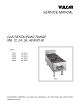
Vulcan-Hart VST4B User manual

Category
Cookers
Type
User manual

This manual is also suitable for

Vulcan-Hart VST4B is a gas fired broiler designed for commercial use. It features fast, efficient gas heat and each burner is controlled by an adjustable on/off gas valve. With 3 burners and a BTU/hr input rating of 135,000, this broiler is perfect for high-volume cooking. The broiler also comes with a griddle plate, making it perfect for cooking a variety of foods. The Vulcan-Hart VST4B is a versatile and powerful broiler that is perfect for any commercial kitchen.

Vulcan-Hart VST4B is a gas fired broiler designed for commercial use. It features fast, efficient gas heat and each burner is controlled by an adjustable on/off gas valve. With 3 burners and a BTU/hr input rating of 135,000, this broiler is perfect for high-volume cooking. The broiler also comes with a griddle plate, making it perfect for cooking a variety of foods. The Vulcan-Hart VST4B is a versatile and powerful broiler that is perfect for any commercial kitchen.

F-35684 (5-07)
VULCAN-HART
DIVISION OF ITW FOOD EQUIPMENT GROUP, LLC
WWW.VULCANHART.COM
INSTALLATION &
OPERATION MANUAL
For additional information on Vulcan-Hart or to locate an authorized parts
and service provider in your area, visit our website at www.vulcanhart.com
CHOP HOUSE
BROILERS
3600 NORTH POINT BLVD.
BALTIMORE, MD 21222
MODEL
VST4B ML-136590
2
IMPORTANT FOR YOUR SAFETY
THIS MANUAL HAS BEEN PREPARED FOR PERSONNEL QUALIFIED TO INSTALL
GAS EQUIPMENT, WHO SHOULD PERFORM THE INITIAL FIELD START-UP
AND ADJUSTMENTS OF THE EQUIPMENT COVERED BY THIS MANUAL.
POST IN A PROMINENT LOCATION THE INSTRUCTIONS TO BE FOLLOWED IN
THE EVENT THE SMELL OF GAS IS DETECTED. THIS INFORMATION CAN BE
OBTAINED FROM THE LOCAL GAS SUPPLIER. IN THE EVENT OF A POWER
FAILURE, DO NOT ATTEMPT TO OPERATE THIS DEVICE.
IMPORTANT
IN THE EVENT A GAS ODOR IS DETECTED, SHUT
DOWN UNITS AT MAIN SHUTOFF VALVE AND
CONTACT THE LOCAL GAS COMPANY OR GAS
SUPPLIER FOR SERVICE.
FOR YOUR SAFETY
DO NOT STORE OR USE GASOLINE OR OTHER
FLAMMABLE VAPORS OR LIQUIDS IN THE
VICINITY OF THIS OR ANY OTHER APPLIANCE.
WARNING
IMPROPER INSTALLATION, ADJUSTMENT,
ALTERATION, SERVICE OR MAINTENANCE CAN
CAUSE PROPERTY DAMAGE, INJURY OR DEATH.
READ THE INSTALLATION, OPERATING AND
MAINTENANCE INSTRUCTIONS THOROUGHLY
BEFORE INSTALLING OR SERVICING THIS
EQUIPMENT.
IN THE EVENT OF A POWER FAILURE, DO NOT
ATTEMPT TO OPERATE THIS DEVICE.
© VULCAN-HART, 2007
3
TABLE OF CONTENTS
INTRODUCTION..............................................................................................................................4
GENERAL...................................................................................................................................4
UNPACKING ..............................................................................................................................4
INSTALLATION..........................................................................................................................4
LOCATION .................................................................................................................................4
CLEARANCES ...........................................................................................................................4
INSTALLATION CODES AND STANDARDS ..........................................................................4
LEG STAND ASSEMBLY INSTRUCTIONS .............................................................................5
Required Tools .....................................................................................................................5
BROILER STAND INSTALLATION INSTRUCTIONS..............................................................5
Required Tools .....................................................................................................................5
CASTER-EQUIPPED BROILERS .............................................................................................6
BURNERS & RADIANTS ...........................................................................................................6
VENTILATION HOOD ...............................................................................................................7
GAS CONNECTION ..................................................................................................................7
GAS PRESSURE REGULATOR INSTALLATION ...................................................................7
OPERATION ....................................................................................................................................8
CONTROLS................................................................................................................................8
LIGHTING THE GAS PILOT .....................................................................................................8
TEMPORARY SHUTDOWN ......................................................................................................8
COMPLETE SHUTDOWN.........................................................................................................8
PREHEATING THE BROILER ..................................................................................................9
GRIDDLE ....................................................................................................................................9
ADJUSTMENTS .........................................................................................................................9
Burner Adjustment ...............................................................................................................9
Grate and Carriage Adjustment ..........................................................................................9
CLEANING ................................................................................................................................. 9
Broiler Grate .........................................................................................................................9
Griddle ............................................................................................................................... 10
Stainless Steel Surfaces .................................................................................................. 10
MAINTENANCE ............................................................................................................................ 11
VENT SYSTEM ....................................................................................................................... 11
SERVICE AND PARTS INFORMATION ............................................................................... 11
GRIDDLE PLATE INSTALLATION ...........................................................................................6
4
GENERAL
Gas fired broilers are designed for commercial
use only and feature fast, efficient gas heat.
Each burner is controlled by an adjustable
on/off gas valve.
Model Number BTU/hr Input
of Burners Rating
3 @ 45,000 ea. 135,000VST4B
UNPACKING
Immediately after unpacking, check for
possible shipping damage. If the broiler is
found to be damaged, save the packaging
material and contact the carrier within 15
days of delivery.
INSTALLATION
Before installing, verify that the type of gas
(natural or propane) and the clearance
dimensions (see below) agree with the
specifications on the rating plate which is
located on right hand side of unit.
Location
The installation location must be kept free and
clear of combustibles. Do not obstruct the
flow of combustion and ventilation air.
Clearances
Check that there are sufficient clearances to
service the broiler and to make the required
gas supply connection(s). Provide 24"
clearance at the front for cleaning,
maintenance, service and proper operation.
INTRODUCTION
Combustible Non-Combustible
Construction Construction
Sides Rear Sides Rear
6 inches 6 inches 0 inches 0 inches
INSTALLATION CODES
AND STANDARDS
The broiler must be installed in accordance
with the following:
In the United States of America:
1. State and local codes.
2. National Fuel Gas Code, ANSI-Z223.1/
NFPA #54 (latest edition). Copies may be
obtained from The American Gas
Association Accredited Standards
Committee Z223, @ 400 N. Capital St. NW,
Washington, DC 20001, or the Secretary
Standards Council, NFPA, 1 Batterymarch
Park Quincy, MA 02169-7471.
3. NFPA Standard #96 Vapor Removal from
Cooking Equipment, latest edition,
available from the National Fire Protection
Association, Batterymarch Park, Quincy,
MA 02269.
4. In the Commonwealth of Massachusetts all
gas appliances vented through a ventilation
hood or exhaust system equipped with a
damper or with a power means of exhaust
shall comply with 248 CMR.
In Canada:
1. Local codes.
2. CAN/CSA-B149.1 Natural Gas Installation
(latest edition).
3.
CAN/CSA-B149.2 Propane Installation Code
(latest edition), available from the Canadian
Gas Association, 178 Rexdale Blvd.,
Etobicoke, Ontario, Canada M9W 1R3.
5
LEG STAND ASSEMBLY
INSTRUCTIONS
Required Tools
7/16" Socket
Philips Head Screw Driver
13/16" Open End Wrench
Shelf
Screw
Nut
Lock
washer
Leg
assembly
Figure 1
1. Insert short end of leg into top of shelf
(Fig. 1).
2. Secure into place with one (1) screw, one
(1) lock washer, and one (1) nut per hole.
3. Repeat leg installation with three (3)
remaining legs.
Locking casters
(front)
Non-locking
casters
(rear)
Figure 2
4. Install the two (2) front locking casters into
the short end of the leg assembly (Fig. 2).
5. Install the rear non-locking casters into
the remaining two (2) leg assemblies.
Tighten nut
Figure 3
6. Secure all four (4) casters by tightening
down the nut on the underside of the
caster.
7. Ensure the two locking casters are located
on the same side of the stand. This will
now be the front of the broiler.
BROILER STAND INSTALLATION
Required Tools
13/16" Open End Wrench
1. Lower Broiler onto the four (4) legs of the
stand, supporting from under the body
bottom (Fig. 4).
Figure 4
w/
6
2. Install two (2) hex head bolts per leg
assembly to secure broiler body onto leg
stand (Fig. 5). (Apply lock-tight to bolt
threads.)
Hex-head
Bolts
Figure 5
CASTER-EQUIPPED BROILERS
Broilers mounted on stands with casters must
use a flexible connector (not supplied) that
complies with the Standard for Connectors
for Movable Gas Appliances, ANSI Z21.69
.
CSA 6.16 and a quick-disconnect device that
complies with the Standard for Quick-
Disconnect Devices for use with Gas Fuel,
ANSI-Z21-41
.
CSA 6.9. In addition, adequate
means must be provided to limit movement of
the broiler without depending on the connector
and the quick-disconnect device or its
associated piping to limit broiler movement.
Attach the restraining device at the rear of the
broiler. If disconnection of the restraint is
necessary, turn off the gas supply before
disconnection.
BURNERS & CERAMIC BRICKS
a) Insert ceramic radiant brick ends at each
corner of the burner frame. Four are required
for each burner (Fig. 6).
b) Tilt ceramic radiant sideways to clear
burner and frame assembly, then lower
radiant into position with one flange resting
on burner ledge and one flange resting on
frame ledge.
c) Install the remaining radiants so 5 radiants
are located on each side of the burner.
Figure 6
GRIDDLE PLATE INSTALLATION
Put the griddle plate on top of the broiler. Duh.
7
GAS PRESSURE REGULATOR
INSTALLATION
A pressure regulator is supplied and must be
installed outside the broiler when making the
gas supply connection. The regulator is preset
at the factory for 6" W.C. (Water Column) for
Natural Gas; 10" W.C. for Propane. No further
adjustment should be required.
Use the 1/8" pipe tap on the burner manifold
for checking pressure. Make sure the gas
piping is clean and free of obstructions, dirt,
and piping compound.
An adequate gas supply is necessary.
Undersized or low pressure lines will restrict the
volume of gas required for satisfactory
performance. The recommended maximum
supply pressure (upstream of the regulator) is
7" W.C. for natural gas and 11" W.C. for propane
gas. With all units operating simultaneously,
the manifold pressure on all units should not
show any appreciable drop. At no time should
the broiler be connected to supply pressure
greater than 1/2 psig (3.45 kPa) or 14" W.C.
Install the regulator as close to the broiler on
the gas supply line as possible. Make sure
that the arrow on the underside of the regulator
is oriented in the direction of gas flow to the
broiler (Fig. 7 and the regulator is positioned
with the vent plug and adjustment screw
upright (Fig. 8).
Figure 7
Figure 8
CAUTION: All gas supply connections
and any pipe joint compound
must be resistant to the
action of propane.
Purge the supply line to clean out any dust,
dirt, or foreign matter before connecting the
line to the unit.
Codes require that a gas shutoff valve be
installed in the gas line ahead of the broiler.
The gas supply line must be at least the
equivalent of 3/4" iron pipe.
When testing the gas supply piping system, if
test pressures exceed 1/2 psig (3.45 kPa), the
broiler and its individual shutoff valve must be
disconnected from the gas supply piping system.
When test pressures are 1/2 psig (3.45 kPa) or
less, the broiler must be isolated from the gas
supply piping system by closing its individual
manual shutoff valve during any pressure testing
of the system.
WARNING: PRIOR TO LIGHTING, CHECK
ALL JOINTS IN THE GAS
SUPPLY LINE FOR LEAKS.
USE SOAP AND WATER
SOLUTION. DO NOT USE
AN OPEN FLAME.
VENTILATION HOOD
The broiler should be installed under a suitable
ventilation hood. For safe operation and proper
ventilation, keep the space between the broiler
and vent hood free from any obstructions.
GAS CONNECTION
The data plate indicates the type od gas and
pressure rate the unit is equipped to burn. DO
NOT connect to any other gas type.
8
OPERATION
The broiler is a free vented appliance. All
products of combustion and the heat generated
by the burners pass through the grates. When
meat is placed on the grates, this blocks the
venting and causes a temperature buildup. The
broiler operates most efficiently with valves
turned down to 1/3 or 1/2.
LIGHTING THE GAS PILOT
1. Turn the individual burner gas valves off
and wait 5 minutes
2. Turn the incoming main gas supply valve
on. Light pilots through grate area by
extending a taper to the pilot lighter tube
up under the broiler area (Fig. 10).
3. To light the burners, turn the individual
burner valves on.
Figure 10
TEMPORARY SHUTDOWN
Turn burner valves off.
COMPLETE SHUTDOWN
For complete shutdown, turn the main gas
supply valve off. (Make sure all individual
burner valves are off before relighting.)
WARNING: THE BROILER AND ITS
PARTS ARE HOT. USE
CARE WHEN OPERATING,
CLEANING, OR SERVICING
THE BROILER.
CONTROLS
Access hole to
pilot adjustment
OFF ONOFF ON
Figure 9
All orifices are of the fixed type and require no
adjustment.
Standing pilots should be adjusted via the
pilot adjustment valve to provide a slight yellow
tip on the flame. Pilots may be lighted by
extending a taper to the pilot lighter tube up
under the broiler area.
When broiling, turn burner control valves to 1/3
or 1/2 to prevent overheating.
When the grate is hot, scrape it with a wire
brush to keep the grate clean. Do not allow
debris to accumulate on the grate.
Turn flame to low setting during slack periods
to conserve energy.
Air shutters on the main burners must be
individually adjusted to provide a blue flame.
All traces of yellow should be adjusted out of
the burner flame. (See burner adjustment.)
9
PREHEATING THE BROILER
Allow the broiler to preheat for 30 minutes.
Note that grease runs forward and drops into
the trough at the front of the broiler before
draining into the grease drawer.
GRIDDLE
The griddle can be used for heating as
required. Griddle heat is controlled by the
broiler burner valves.
ADJUSTMENTS
Burner Adjustment
The efficiency of the broiler depends on a
delicate balance between the supply of air
and the volume of gas so that complete
combustion is achieved. Whenever this
balance is disturbed, poor operating
characteristics occur.
The air supply is controlled by an air shutter on
the front of the burners. The air shutter openings
should be increased until the flame on the
burner begins to “lift.” The air shutter should
then be closed slightly and locked in place. A
yellow streaming flame indicates insufficient air
(Fig. 11). This condition could be corrected by
increasing the air shutter opening.
Figure 11
Grate and Carriage Adjustment
If carriage tension is too strong, turn adjusting
nuts counterclockwise. If one side of the grate
is lower than the other side, turn adjusting nut
on the low side clockwise to level (Fig. 12).
Adjustment should be made with the grate irons
in place and allowance for product weight.
The adjusting nut is accessible from the front
as shown in Fig. 12.
Figure 12
Grate and carriage adjustments should be
done by authorized service personell only.
All burner air shutters are adjusted at the plant
but may need to be readjusted depending on
gas mixtures and altitudes at each location.
Start broiler burners and let them run for
15 minutes. Check each burner flame for
approx. a 1" high flame with a little yellow tip on
the ends.
If flame is larger or smaller than 1" the burner
shutter must be adjusted. One burner at a time,
loosen shutter screw and open slowly until flame
reaches approx. 1" high. Retighten screw.
Repeat on remaining burners needing adjustment.
Air Shutter Adjustment
10
The lower broiler grease can and the left
side griddle grease chute can be removed
for cleaning (use wire brush).
Griddle
Clean using mild detergent and griddle screen
as needed.
Stainless Steel Surfaces
There are four things that will break down
stainless steel and allow corrosion to develop:
1) abrasion
2) deposits
3) water
4) chlorides
Avoid rubbing with steel pads, wire brushes or
scrapers that can leave iron deposits on stainless
steel. Instead, use plastic scouring pads or soft
cloths. For stubborn stains, always rub parallel
to the polish lines or with the grain.
Hard water will leave deposits that promote rust
on stainless steel. Treated water from softeners
or certain filters can eliminate these mineral
deposits. Other deposits from food or lubrication
must be properly removed by cleaning. Use
mild detergent and non-chloride cleaners. Rinse
thoroughly and wipe dry. Where appropriate,
apply a polish recommended for stainless steel
(such as Benefit or Super Sheen) for extra
protection and luster.
CLEANING
Broiler Grate
Scrape grate thoroughly after each use so
grease flows to drip pan. Ensure that the
grease drawer remains uninhibited. This
prevents flare-ups.
Dispose of grease regularly. Do not allow
drawer to overflow.
After being allowed to cool to at least 200°F,
grates may be removed and immersed in
commercial cleaning compound overnight. In
the morning, rinse with hot water to remove
any residues of cleaning compound.
Grease Chutes
11
MAINTENANCE
WARNING: THE BROILER AND ITS
PARTS ARE HOT. USE
CARE WHEN OPERATING,
CLEANING, OR SERVICING
THE BROILER.
VENT SYSTEM
At least twice a year, the exhaust hood (venting
system) should be examined and cleaned.
SERVICE AND PARTS INFORMATION
To obtain service and parts information
concerning this model, contact Vulcan-Hart
or refer to our website:
www.vulcanhart.com
for a complete listing of Authorized Service
and Parts depots.
When calling for service, have the model number
and serial number available.
— 2 —
GRILLOIRS AU GAZ
© COMPAGNIE VULCAN-HART, 2007
MESURES DE SÉCURITÉ IMPORTANTES
CE MANUEL A ÉTÉ PRÉPARÉ À L’INTENTION D’UN PERSONNEL QUALIFIÉ ET
AUTORISÉ À INSTALLER DES APPAREILS FONCTIONNANT AU GAZ ET À
EFFECTUER LE DÉMARRAGE INITIAL CHEZ LE CLIENT DE MÊME QUE LE RÉGLAGE
DES APPAREILS CONCERNÉS DANS CE MANUEL.
AFFICHER À UN ENDROIT VISIBLE LES PREMIERS SOINS À ADMINISTRER À TOUTE
PERSONNE AYANT RESPIRÉ LES GAZ QUE CET APPAREIL DÉGAGE. ON PEUT SE
PROCURER CES INFORMATIONS CHEZ LE FOURNISSEUR DE GAZ LE PLUS PRÈS.
EN CAS DE PANNE DE COURANT, NE PAS FAIRE
FONCTIONNER CET APPAREIL.
AVERTISSEMENT
L’INSTALLATION, LE RÉGLAGE, LA MODIFICATION
ET L’ENTRETIEN INCORRECTS DE CET APPAREIL
PEUVENT CAUSER DES DOMMAGES MATÉRIELS,
DES BLESSURES ET MÊME LA MORT. LIRE LES
INSTRUCTIONS D’INSTALLATION, DE FONCTIONNEMENT
ET D’ENTRETIEN AVANT DE PROCÉDER À TOUTE
INSTALLATION OU TOUT ENTRETIEN.
MESURE DE SÉCURITÉ
NE PAS RANGER NI UTILISER DE L’ESSENCE NI TOUT
AUTRE LIQUIDE OU VAPEUR INFLAMMABLE À
PROXIMITÉ DE CET APPAREIL OU DE TOUT AUTRE
APPAREIL.
IMPORTANT
EN CAS D’ODEURS DE GAZ, ÉTEINDRE L’APPAREIL PAR
LE ROBINET D’ARRÊT PRINCIPAL ET COMMUNIQUER
AVEC LA COMPAGNIE DE GAZ LA PLUS PRÈS OU
AVEC LE FOURNISSEUR DE GAZ ATTITRÉ POUR
L’ENTRETIEN.
  • Page 1 1
  • Page 2 2
  • Page 3 3
  • Page 4 4
  • Page 5 5
  • Page 6 6
  • Page 7 7
  • Page 8 8
  • Page 9 9
  • Page 10 10
  • Page 11 11
  • Page 12 12
  • Page 13 13
  • Page 14 14
  • Page 15 15
  • Page 16 16
  • Page 17 17
  • Page 18 18
  • Page 19 19
  • Page 20 20
  • Page 21 21
  • Page 22 22
  • Page 23 23
  • Page 24 24

Vulcan-Hart VST4B User manual

Category
Cookers
Type
User manual
This manual is also suitable for

Vulcan-Hart VST4B is a gas fired broiler designed for commercial use. It features fast, efficient gas heat and each burner is controlled by an adjustable on/off gas valve. With 3 burners and a BTU/hr input rating of 135,000, this broiler is perfect for high-volume cooking. The broiler also comes with a griddle plate, making it perfect for cooking a variety of foods. The Vulcan-Hart VST4B is a versatile and powerful broiler that is perfect for any commercial kitchen.

Ask a question and I''ll find the answer in the document

Finding information in a document is now easier with AI

in other languages