Pro'sKit MT-1132 Owner's manual
- Category
- Multimeters
- Type
- Owner's manual
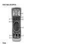
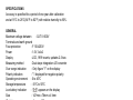
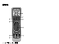
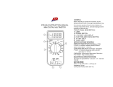
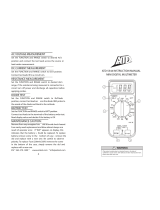
Pro'sKit MT-1132 is a handheld digital multimeter designed to measure DC and AC voltage, DC current, resistance, continuity, test diodes, and transistors. It features a 3 1/2 digit LCD display with a maximum reading of 1999 counts, data hold function to freeze the display, and a backlight for easy reading in low-light conditions. The MT-1132 also includes a continuity beeper for quickly identifying open and short circuits, and a transistor tester for checking the hFE of bipolar transistors.
Pro'sKit MT-1132 is a handheld digital multimeter designed to measure DC and AC voltage, DC current, resistance, continuity, test diodes, and transistors. It features a 3 1/2 digit LCD display with a maximum reading of 1999 counts, data hold function to freeze the display, and a backlight for easy reading in low-light conditions. The MT-1132 also includes a continuity beeper for quickly identifying open and short circuits, and a transistor tester for checking the hFE of bipolar transistors.


-
 1
1
-
 2
2
-
 3
3
-
 4
4
-
 5
5
-
 6
6
-
 7
7
-
 8
8
-
 9
9
-
 10
10
-
 11
11
-
 12
12
-
 13
13
-
 14
14
-
 15
15
-
 16
16
-
 17
17
-
 18
18
-
 19
19
-
 20
20


Pro'sKit MT-1132 Owner's manual
- Category
- Multimeters
- Type
- Owner's manual
Pro'sKit MT-1132 is a handheld digital multimeter designed to measure DC and AC voltage, DC current, resistance, continuity, test diodes, and transistors. It features a 3 1/2 digit LCD display with a maximum reading of 1999 counts, data hold function to freeze the display, and a backlight for easy reading in low-light conditions. The MT-1132 also includes a continuity beeper for quickly identifying open and short circuits, and a transistor tester for checking the hFE of bipolar transistors.
Ask a question and I''ll find the answer in the document
Finding information in a document is now easier with AI
Related papers
Other documents
-
Mastech MS8233A User manual
-
 ATD Tools ATD-5544 User manual
-
 ATD Tools ATD-5544 User manual
-
Triplett BBT858L User manual
-
Philex 83002R User manual
-
Advantage ADV1010 User manual
-
Velleman VTSET24 User manual
-
3B SCIENTIFIC PHYSICS E 1006809 Instruction Sheet
-
Mastech M839b User manual
-
Elenco M1007K Owner's manual

