Page is loading ...

XCELLENCE SERIES
X12CE - X15CE - X15LTE - X18WE
Pol. Ind. Norte - Perpinyà, 25
08226 TERRASSA
Copyright © 2012 [email protected]
All rights reserved master-audio.com
Nov 12
User’s manual / Manual usuario

ENGLISH
Safety Instructions
1. All safety instructions must be read before using this device.
2. The exclamation mark in the triangle indicates internal components which if
replaced can affect safety.
3. The lightning symbol within the triangle indicates the presence of dangerous
uninsulated voltages.
4. This device must not be exposed to rain or humidity. It must not be used for
example near swimming pools, fountains or any other place where it might be
affected by liquids.
5. Only clean the device with a dry cloth.
6. Do not situate the equipment where its ventilation system might be interfered with.
7. Do not install the device near heat sources such as radiators, heaters or other
heat-emitting elements.
8. The equipment must be repaired by qualified technical service personnel when:
A. The mains supply cable is damaged, or
B. Any object or liquid has damaged the device; or
C. The equipment does not function normally or correctly; or
D. The equipment has been exposed to the rain; or
E. The chassis is damaged
9. Disconnect the device in the case of electric storms or during long periods of
disuse.
10. Never hang the equipment by its handle.
11. Only use manufacturer recommended accessories.
CAUTION
RISK OF ELECTRIC SHOCK
DON’T OPEN
To reduce the risk of fire or electric shock do
not expose this equipment to rain or moisture
WARNING:

Master Audio
Xcellence “E “Series. Ver1.0 Nov12
3
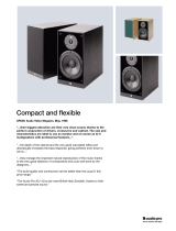
1. INTRODUCTION
1.1. General product information
Master Audio thank you for the trust placed in our Xcellence loudspeaker systems.
The Xcellence series combines the convenience of a self-powered system and the
flexibility of the DSP (digital system processing) for cabinet control.
More than 40 years’ experience in amplifier and acoustic cabinet design using the
highest technology and components come together to give you a product ideal for a
multitude of applications, from sound back-up systems for theatres, clubs or TV
channels to even churches, corporative events or concert halls.
Coaxial technology in X12CE and X15CE achieves a sound distribution system which
is totally coherent and in phase (as a point source). This is due to the fact that the
directivity of the high and low frequency transducers couples up perfectly with the
crossover frequency from the filters. This results in very smooth transitions between
the bass and high frequency zone and the elimination of secondary null zones due to
polar lobbing. The directivity of the cabinets with coaxial transducers is totally
symmetric in the horizontal or vertical plane.
We suggest you read the following information with attention, assured that it will be of
maximum use in helping you to achieve the best results and optimum performance.
1.2. Features and appearance
X12CE & X15CE
- Self-powered cabinet.
- 800W amplifier for mid-bass range.
- 200W amplifier for high range.
- 24-bit AD/DA converters with 112dB dynamic range, 96kHz sampling rate.
- DSP Controls (parametric EQs, delay, volume, polarity and limiters).
- Amplifier self-diagnostics: output power, temperature, clipping.
- Ethernet connectivity.
- Overvoltage protection (>250V-400V).
- Two-way coaxial speaker with 80º symmetry, including one 12” woofer (X12CE) and
one 15” woofer (X15CE) in neodymium and one 3” voice coil diameter, titanium
diaphragm compression driver.
- Birch plywood construction.
- Polyurea black textured paint finish.
- Frontal steel grille with acoustically transparent grey cloth.
X15LTE
- Self-powered cabinet.
- 1000W amplifier for mid-bass range.
- 200W amplifier for high range.
- 24-bit AD/DA converters with 112dB dynamic range, 96kHz sampling rate.
- DSP Controls (parametric EQ, delay, volume, polarity and limiters).
- Amplifier self-diagnostics: output power, temperature, clipping.

Master Audio
Xcellence “E “Series. Ver1.0 Nov12
4
- Ethernet connectivity.
- Overvoltage protection (>250V-400V).
- One 15” woofer in neodymium (4” voice coil).
- One 3” voice coil diameter, titanium diaphragm compression driver.
- 60º x 50º rotatable horn.
- Birch plywood construction.
- Polyurea black textured paint finish.
- Frontal steel grille with acoustically transparent grey cloth.
X18WE Subwoofer
- Self-powered cabinet.
- 2400W amplifier for bass range.
- 24-bit AD/DA converters with 112dB dynamic range, 96kHz sampling rate.
- DSP Controls (parametric EQs, delay, volume, polarity and limiter).
- Amplifier self-diagnostics: output power, temperature, clipping.
- Ethernet connectivity.
- Overvoltage protection (>250V-400V).
- 18” speaker in neodymium, 4” voice coil and demodulation rings to reduce distortion
and the transitory response.
- Birch plywood construction.
- Polyurea black textured paint finish.
- Frontal steel grille with acoustically transparent grey cloth.
2. X12CE & X15CE FEATURES
The X12CE & X15CE cabinets are ideal for a multitude of applications. They include
800W bi-amplification for the mid range woofer, 200W for the high range compression
driver and digital signal control by DSP. The manufacturer presets FACTORY,
NEARFIELD, SPEECH, MONITOR, and XOVER make it easy, flexible and user-
friendly.
In terms of its electro-acoustic qualities, the coaxial transducer gives a totally
symmetrical response free of null zones from polar lobbing effect. It comprises a 12”
or 15” woofer with a 3” voice coil and a compression driver with 3” voice coil and
titanium diaphragm.
The result is a clean, high quality sound whether for nearfield listening or at full power
in larger sites.
Thanks to its wedge shape it can be used as an onstage monitor, obtaining stable,
homogeneous response and coverage.
The upper and lower surfaces incorporate a pole mount socket for a standard 35mm
tripod, which at the same time allows for the use of a UBX hanging support (see
accessories).
2.1. Technical description
The X12CE and X15CE cabinets come with DSP control, full range sound delivery
thanks to their direct radiation coaxial transducer and acoustic bass reflex cabinet. As
a full range system, its response is 58Hz-18kHz (+/- 3dB) with a usable bandwidth

Master Audio
Xcellence “E “Series. Ver1.0 Nov12
5
between 50Hz-20kHz (-10dB) for X-12CE and 53Hz-18kHz (+/- 3 dB) with a usable
bandwidth between 45Hz-20kHz (-10dB) for X-15CE.
They have 1000W continuous amplification (800W + 200W), thermal protection,
output short circuit protection, maximum power limiters for each channel, and
protection against overvoltage. The DSP includes 5 presets which can be selected
either accessing the cabinet’s rear control panel or via the computer with Ethernet
connection. The FACTORY preset gives a maximum flat response in free field
conditions; NEARFIELD has -3dB in mid range for medium volume, close range
listening; SPEECH has -9dB bass, -6dB high for voice use with a microphone;
MONITOR gives a flat response in half space (floor position); XOVER has a high
pass filter at 100Hz for bass frequency back up (subwoofer).
The X12CE and X15CE cabinets are connected using the XLR balanced connector.
Mains supply is through PowerCon at 230V.
They are built in birch plywood, which has a high resistance to vibrations and
humidity with black polyurea paint finish. The front face is protected by a 1.5 mm thick
steel grille with acoustically transparent grey cloth.
Wedge shape. As onstage monitor, the front baffle is oriented at 35º from vertical.
They include one in-built lateral handle for an easy and comfortable transport.
Fig.1. X12CE and X15CE external dimensions
2.2. Presets
The X12CE and X15CE include five manufacturer presets for different types of
application. The DSP system can also store up to 23 other presets, depending on
user requirements

Master Audio
Xcellence “E “Series. Ver1.0 Nov12
6
P1-FACTORY
Flat response
• Standard preset
P2-NEARFIELD
-3dB mid
• Small venues
• Medium level
• Short-medium
distance
P3-SPEECH
-9dB Low
-6dB High
• Microphone use
• No matter level
or distance
P4-MONITOR
Flat response
• floor use
P5-XOVER
HPF 100Hz
• use with
subwoofer
Fig.2. PRESET options for X12CE and X15CE

Master Audio
Xcellence “E “Series. Ver1.0 Nov12
7
3. X15LTE FEATURES
The X15LTE cabinet is ideal for a multitude of applications. It includes 1000W bi-
amplification for the mid range woofer, 200W for the high range compression driver
and digital signal control by DSP. The manufacturer presets FACTORY, NEARFIELD,
LOUDNESS, SPEECH and XOVER make it easy, flexible and user-friendly.
The result is a clean, high quality sound whether for nearfield listening or at full power
in larger sites.
The lower surface incorporates a pole mount socket for a standard 35mm tripod and
the top surface incorporates a M10 thread.
3.1. Technical description
The X15LTE cabinet comes with DSP control, full range sound delivery thanks to its
direct radiation transducer and acoustic bass reflex cabinet. As a full range system,
its response is 50Hz-18kHz (+/- 3dB) with a usable bandwidth between 42Hz-19kHz
(-10dB).
It has 1200W continuous amplification (1000W + 200W), thermal protection, output
short circuit protection, maximum power limiters for each channel, and protection
against overvoltage. The DSP includes 5 presets which can be selected either
accessing the cabinet’s rear control panel or via the computer with Ethernet
connection. The FACTORY preset gives a maximum flat response in free field
conditions; NEARFIELD has -3dB in mid range for medium volume, close range
listening; LOUDNESS has -6dB in mid range for medium volume with more mid range
correction; SPEECH has -6dB bass, -6dB high for voice use with a microphone;
XOVER has a high pass filter at 100Hz for bass frequency back up (subwoofer).
The X15LTE cabinet is connected using the XLR balanced connector. Mains supply
is through PowerCon at 230V. It is built in birch plywood, which has a high resistance
to vibrations and humidity with black polyurea paint finish. The front face is protected
by a 1.5 mm thick steel grille with acoustically transparent grey cloth.
Fig.3. X15LTE external dimensions

Master Audio
Xcellence “E “Series. Ver1.0 Nov12
8
3.2. Presets
The X15LTE includes five manufacturer presets for different types of application. The
DSP system can also store up to 23 other presets, depending on user requirements
P1-FACTORY
Flat response
• Standard preset
P2-NEARFIELD
-3dB mid
• Small venues
• Medium level
• Short-medium
distance
P3-LOUDNESS
-6dB mid
• Small venues
• Medium level
• Short-medium
distance
• Deeper mid
correction
P4-SPEECH
-6dB low
-6dB high
• Microphone use
• No matter level
or distance

Master Audio
Xcellence “E “Series. Ver1.0 Nov12
9
P5-XOVER
HPF 100Hz
• use with
subwoofer
Fig.4. PRESET options for X15LTE
4. X18WE FEATURES
The X18WE cabinet is ideal for bass reinforcement in general and specifically in
combination with models X12CE, X15CE and X15LTE. It includes 2400W
amplification for the woofer and digital signal control by DSP. The manufacturer
presets (LPF90+3, LPF90+6, LPF110+3, LPF110+6, LPF130+3, LPF130+6,
CARDIOID) make it easy, flexible and user-friendly.
The 18” neodymium woofer used, thanks to its exclusive magnetic design, combines
excellent bass frequency response, high performance and low distortion. These
features are mainly due to the presence of demodulation rings which drastically
reduce the inter-modulation and third order distortion and considerably improve the
transitory response. There is excellent heat dissipation due to the external positioning
of the magnet set. Without any doubt one of the finest bass transducers currently
available. The result is a clean, high quality sound.
The upper surface incorporates a pole mount socket for a standard 35mm bar.
4.1. Technical description
The X18WE cabinet comes with DSP control, with direct radiation transducer and
acoustic bass reflex cabinet. As a bass reinforcement system, its frequency response
is 35Hz-130Hz (+/- 3dB) with a usable bandwidth between 30Hz-140Hz (-10dB).
It has 2000W continuous amplification, thermal protection, output short circuit
protection, maximum power limiters for each channel, and protection against
overvoltage. The DSP includes 7 presets which can be selected either accessing the
cabinet’s rear control panel or via the computer with Ethernet connection. The
LPF90+3 preset means low pass filter at 90Hz and +3dB boost at 50Hz; LPF90+6
means low pass filter at 90Hz and +6dB boost at 50Hz; LPF110+3 means low pass
filter at 110Hz and +3dB boost at 50Hz; LPF110+6 means low pass filter at 110Hz
and +6dB boost at 50Hz; LPF130+3 means low pass filter at 130Hz and +3dB boost
at 50Hz; LPF130+6 means low pass filter at 130Hz and +6dB boost at 50Hz and
CARDIOID means cardioid polar pattern when used in combination with two other
X18WE subwoofers.
By upping the low pass filter a greater ‘boom’ sensation can be achieved, but clarity is
lost. It is down to the user to decide on the most suitable preset.

Master Audio
Xcellence “E “Series. Ver1.0 Nov12
10
The X18WE is connected using the XLR balanced connectors. Mains supply is
through PowerCon at 230V.
It is built in birch plywood, which has a high resistance to vibrations and humidity with
black polyurea paint finish. The front face is protected by a 1.5 mm thick steel grille
with acoustically transparent grey cloth.
Fig.5. X18WE external dimensions
4.2. Presets
The X18WE includes seven manufacturer presets for different types of application.
The DSP system can also store up to 23 other presets, depending on user
requirements.
ATTENTION: When the X18WE is used in conjunction with the X12CE, X15CE or
X15LTE in XOVER preset, the X18WE must operate in positive polarity.
When the X18WE is used in conjunction with the X12CE, X15CE or X15LTE in
FACTORY, NEARFIELD, LOUDNESS, SPEECH or MONITOR presets, the X18WE
must operate in negative polarity.
P1-LPF90+3
Low pass filter at 90Hz
with +3dB boost
at 50Hz

Master Audio
Xcellence “E “Series. Ver1.0 Nov12
11
P2-LPF90+6
Low pass filter
at 90Hz with +6dB
boost at 50Hz
P3-LPF110+3
Low pass filter
at 110Hz with +3dB
boost at 50Hz
P4-LPF110+6
Low pass filter
at 110Hz with +6dB
boost at 50Hz
P5-LPF130+3
Low pass filter
at 130Hz with +3dB
boost at 50Hz
P6-LPF130+6
Low pass filter
at 130Hz with +6dB
boost at 50Hz

Master Audio
Xcellence “E “Series. Ver1.0 Nov12
12
P7-CARDIOID
(Cardioid
polar pattern, with
delay and inverse
polarity)
Fig.6. X18WE PRESET options
5. CONTROL AND CONNECTION PANELS
The X12CE, X15CE and X15LTE control panels contain the following elements:
Fig.7. X12CE,
X15CE and
X15LTE control
and connection
panel
A
B
E
D
C
G
F
H
I

Master Audio
Xcellence “E “Series. Ver1.0 Nov12
13
A) LCD: Displays basic information about the DSP Status
B) KEYPAD: Allows the user to perform basic operations on the DSP such as IP
address setting, Preset selection, etc.
C) STATUS LEDS: Report a special event happening in the system
Protect: (Red) A fault condition is being reported by the amplifier. If this LED is
constantly lit even after resetting the device, please contact the technical
service.
Standby: (Orange) This led is lit when the equipment is set in Low Power
Consumption mode. This mode can only be set through the PC connection.
Mute: (Orange) The system is muted (amplifiers are disabled). The system
can be muted from the PC remote control or from the keypad.
IMPORTANT: When the amplifier is in MUTE, the PROTECT LED will be also lit to
show that the amplifier is disabled. Also when the system is waking up from the
STANDBY mode, the PROTECT led will be lit for a few seconds. Under these
circumstances the PROTECT LED is reporting that the amplifier is disabled, but not a
fault condition.
D) SIGNAL INPUT LEDS: Monitor the signal arriving at the module input.
Input: Signal is present at the input. Nominal input level is +8dBu (2Vrms).
>8 Overload: The input signal exceeds +14dBu (4Vrms), so it will be
compressed. Avoid the continuous lighting of this led in order to preserve the
dynamic range of the audio signal.
E) OUPUT LEDS: Show the amplifier output level, both for Low and High channels.
-24dB: The amplifier is delivering output power at -24dB of its maximum power
-12dB: The amplifier is delivering output power at -12dB of its maximum power
Clip: The amplifier is delivering its maximum output power
The connection panel has the following parts:
F) NETWORK: Computer connection through Ethernet protocol. Two 8-pin RJ45 /
EtherCon® compatible connectors with an internal switch allow the connection of
several units in daisy-chain. Please refer to Master Audio DSPStudio Quick Installation
Guide for more information on the remote connection.
G) BALANCED INPUT/LINK:
XLR-3 Female balanced signal connector for signal input.
XLR-3 Male connector for parallel connection of various cabinets with the same input
signal.
IMPORTANT: Please always use balanced microphone cable with the following pin
assignment:
1= Shield (Ground) 2= Live (+) 3= Return (-)
H) AC INPUT/OVERVOLTAGE PROTECTION: These leds show the status of the
AC mains supply.
ON: (Blue) When lit, the equipment is ON and the AC input level is within the
permitted range (up to 250 VAC).

Master Audio
Xcellence “E “Series. Ver1.0 Nov12
14
STANDBY: (Orange) This led is lit when the equipment is sensing the AC
voltage at the input. At power-up this led will lit for a second while the systems
checks for the input voltage.
>250V OVERVOLTAGE PROTECTION: (Red) When activated, the AC
voltage is permanently out of the permitted range of the equipment, so it will
remain under protection until this condition is solved. Revise your connections
and mains power installation and consider that other equipment connected to
this line may have been damaged.
I) AC MAINS INPUT/LINK: Mains supply connection via PowerCon.
Blue connector for AC in.
Grey connector to feed other units in parallel. Linking up to 4 units is possible,
provided that a quality cable of a minimum section of 3x2.5mm
2
is used.
Connecting more than 4 units in parallel may lead to a voltage drop in the cable
that will reduce the equipment performance.
Always use mains power cable supplied by manufacturer.
Never connect the Xcellence Line Array cabinets to an unearthed mains
supply or by using an unearthed mains cable.
The X18WE control panel contains the following elements:
A) LCD: Displays basic information about the DSP Status
B) KEYPAD: Allows the user to perform basic operations on the DSP such as IP
address setting, Preset selection, etc.
C) STATUS LEDS: Report a special event happening in the system
Protect: (Red) A fault condition is being reported by the amplifier. If this LED is
constantly lit even after resetting the device, please contact the technical
service.
Standby: (Orange) This led is lit when the equipment is set in Low Power
Consumption mode. This mode can only be set through the PC connection.
Mute: (Orange) The system is muted (amplifiers are disabled). The system
can be muted from the PC remote control or from the keypad.
IMPORTANT: When the amplifier is in MUTE, the PROTECT LED will be also lit to
show that the amplifier is disabled. Also when the system is waking up from the
STANDBY mode, the PROTECT led will be lit for a few seconds. Under these
circumstances the PROTECT LED is reporting that the amplifier is disabled, but not a
fault condition.
D) SIGNAL INPUT LEDS: Monitor the signal arriving at the module input.
Input: Signal is present at the input. Nominal input level is +8dBu (2Vrms).
>8 Overload: The input signal exceeds +14dBu (4Vrms), so it will be
compressed. Avoid the continuous lighting of this led in order to preserve the
dynamic range of the audio signal.
E) OUPUT LEDS: Show the amplifier output level
-24dB: The amplifier is delivering output power at -24dB of its maximum power
-12dB: The amplifier is delivering output power at -12dB of its maximum power
Clip: The amplifier is delivering its maximum output power

Master Audio
Xcellence “E “Series. Ver1.0 Nov12
15
The connection panel has the following parts:
F) NETWORK: Computer connection through Ethernet protocol. Two 8-pin RJ45 /
EtherCon® compatible connectors with an internal switch allow the connection of
several units in daisy-chain. Please refer to Master Audio DSPStudio Quick Installation
Guide for more information on the remote connection.
G) BALANCED INPUT/LINK:
XLR-3 Female balanced signal connector for signal input.
XLR-3 Male connector for parallel connection of various cabinets with the same input
signal.
IMPORTANT: Please always use balanced microphone cable with the following pin
assignment:
1= Shield (Ground) 2= Live (+) 3= Return (-)
Fig.8. X18WE control and connection panel
H) AC INPUT/OVERVOLTAGE PROTECTION: These leds show the status of the
AC mains supply.
ON: (Blue) When lit, the equipment is ON and the AC input level is within the
permitted range (up to 250 VAC).
STANDBY: (Orange) This led is lit when the equipment is sensing the AC
voltage at the input. At power-up this led will lit for a second while the systems
checks for the input voltage.
>250V OVERVOLTAGE PROTECTION: (Red) When activated, the AC
voltage is permanently out of the permitted range of the equipment
(>250VAC), so it will remain under protection until this condition is solved.
Revise your connections and mains power installation and consider that other
equipment connected to this line may have been damaged.
A
B
C
D
E
F
G
H
I

Master Audio
Xcellence “E “Series. Ver1.0 Nov12
16
I) AC MAINS INPUT/LINK: Mains supply connection via PowerCon.
Blue connector for AC in.
Grey connector to feed other units in parallel. Linking up to 2 units is possible,
provided that a quality cable of a minimum section of 3x2,5 mm
2
is used.
Connecting more than 2 units in parallel may lead to a voltage drop in the cable
that will reduce the equipment performance.
6. CARDIOID SUBWOOFER X18WE
The X18WE enables the combination of three or multiple of three subwoofer cabinets
in an array to provide exceptional directivity at low frequencies.
High directivity at low frequencies has two main effects on the sound field: firstly, the
low frequency level behind the subwoofer cabinets is greatly reduced; secondly, in
closed venues the diffuse sound field at low frequencies is reduced so the low
frequency reproduction is much more precise.
The typical operating range of a traditional subwoofer tends to be like a monopole,
i.e. tends to radiate with the same energy in all directions. This behaviour implies that
the control of radiation at low frequencies is very difficult because the wavelengths
are very large compared to the size of the source (8.5 m at 40Hz).
Fig.9. Traditional polar pattern of a subwoofer at 40Hz
To increase the directivity at low frequencies we must transform the omnidirectional
performance into a cardioid performance. This can only be achieved by various
sources, arranged in a certain position, to which we apply a specific phase, filtering
and delay. That is, we need to reproduce two signals with the same frequency and
similar amplitude which will have a difference in phase of approximately 180º at a
certain point of the sound field. If the phases and delays are well calculated the result
is a system in which we cancel the energy of the back and not the one of the front.
This can only be achieved with cabinets that incorporate independent delay units on
their DSP, as X18WE.
Fig.10. Cardioid pattern

Master Audio
Xcellence “E “Series. Ver1.0 Nov12
17
6.1. The CARDIOID preset
The X18WE can generate an uncompromised cardioid behaviour, which means that
there is no need for special cabinets, enabling the use of the system’s full efficiency
with just “one finger”.
In its minimum configuration a Cardioid setup consists of a stack of three subwoofer
cabinets.
Only one subwoofer is needed to compensate for the energy of the other two radiating
to the front. Then, the cabinet facing to the back (to the stage) should be located in the
centre of the column.
Fig.11. Cardioid configuration for X18WE subwoofer
The front facing subwoofers must be driven with [LPF90+3] or [LPF90+6] preset
and the back facing subwoofer must be driven with [CARDIOID] preset.

Master Audio
Xcellence “E “Series. Ver1.0 Nov12
18
[LPF90+3]
[LPF90+6]
[CARDIOID]
[LPF90+3]
[LPF90+6]
Fig.12. Presets for cardioid configuration
Fig.13. Back energy rejection at 40Hz / 50 Hz / 63Hz
IMPORTANT: If the user wants to adjust its own cardioid preset there is a
specific manual to do it. Please, contact the sales department of Master Audio
for more information.
7. CONNECTING
7.1. Parallel connection
Connect the signal (mixing desk output) to INPUT on the first unit. Use the LINK
output to transfer the INPUT signal to the second unit and thus sequentially for further
units. All of the units in this chain must be switched on.
For the mains connection in parallel use the cable with grey Neutrik PowerCon
NAC3FCB at one end and the blue Neutrik PowerCon NAC3FCA at the other end.
Do not connect more than 4 X12CE, X15CE or X15LTE units using the
AC Stacking output connector.

Master Audio
Xcellence “E “Series. Ver1.0 Nov12
19
Do not connect Xcellence series units in parallel using PowerCon- PowerCon without
earth.
Fig.14. Parallel connection for the XcellenceE series(signal)
Fig.15. Parallel connection for the XcellenceE series (mains)
7.2. Parallel connection with subwoofer
You can connect the X18WE subwoofer in parallel with X12CE, X15CE or X15LTE
cabinets. Please, follow the same parameters as explained in figures 14 and 15.
Never connect more than 4 units using the AC Stacking socket.
8. OVERVOLTAGE PROTECTION
The Xcellence series models incorporate an exclusive protection by Master Audio
against mains voltage overload and other related problems (lose of neutral,
connection between phases, etc)
In the mains input an electronic circuit compares the input voltage with a reference
value. When the input exceeds 250 Volts, the circuit reacts by blocking the input
tension until it returns to its correct limits (230V +/- 10%).

Master Audio
Xcellence “E “Series. Ver1.0 Nov12
20
When the overvoltage LED lights up red, the unit stops running, until the correct
voltage is re-established.
Generally the cause of such an anomaly tends to be a neutral voltage drop or
incorrect connection of the equipment to 400V supply. Whenever the overvoltage
LED lights up, check the tension of the electrical phases: other devices in the sound
system are also at risk of electrical fault and severe damage.
9. MOUNTING AND INSTALLATION
Whenever possible, mount the Full Range units in a high position (between 2 and 3
meters above ground), angled towards the audience. If the units are mounted close to
the ground the back row listeners will receive low quality sound.
Fig.16. Orientation of Xcellence full range units
The X12CE and X15CE models incorporate a 35mm pole mount socket for standard
tripod in the upper and lower sides.
To use the socket, unscrew the four bolts on the central face plate.
Fig.17. Socket for tripod (X12CE, X15CE)
Fig.18. Top side (left) and socket for tripod (right) for X15LTE
/