
1
INSTRUCTION MANUAL
MANUEL D'INSTRUCTION
MANUAL DE INSTRUCCIONES
DOUBLE INSULATION
DOUBLE ISOLATION
DOBLE AISLAMIENTO
IMPORTANT: Read Before Using.
IMPORTANT: Lire avant usage.
IMPORTANTE: Leer antes de usar.
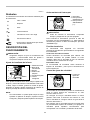
Trimmer
Affleureuse
Recortadora
RT0700C
RT0701C
011833

2
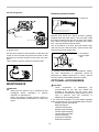
ENGLISH (Original instructions)
SPECIFICATIONS
Model RT0700C / RT0701C
Collet chuck capacity 1/4", 3/8"
No load speed (RPM) 10,000 - 30,000 /min
Overall length 200 mm (7-7/8")
Net weight 1.8 (3.9 lbs)
• Due to our continuing program of research and development, the specifications herein are subject to change without notice.
• Specifications may differ from country to country.
• Weight according to EPTA-Procedure 01/2003
GEA008-2
General Power Tool Safety
Warnings
WARNING Read all safety warnings and all
instructions.
Failure to follow the warnings and instructions
may result in electric shock, fire and/or serious injury.
Save all warnings and
instructions for future reference.
The term "power tool" in the warnings refers to your
mains-operated (corded) power tool or battery-operated
(cordless) power tool.
Work area safety
1. Keep work area clean and well lit. Cluttered or
dark areas invite accidents.
2. Do not operate power tools in explosive
atmospheres, such as in the presence of
flammable liquids, gases or dust. Power tools
create sparks which may ignite the dust or fumes.
3. Keep children and bystanders away while
operating a power tool. Distractions can cause
you to lose control.
Electrical Safety
4. Power tool plugs must match the outlet. Never
modify the plug in any way. Do not use any
adapter plugs with earthed (grounded) power
tools. Unmodified plugs and matching outlets will
reduce risk of electric shock.
5. Avoid body contact with earthed or grounded
surfaces such as pipes, radiators, ranges and
refrigerators. There is an increased risk of
electric shock if your body is earthed or grounded.
6. Do not expose power tools to rain or wet
conditions. Water entering a power tool will
increase the risk of electric shock.
7. Do not abuse the cord. Never use the cord for
carrying, pulling or unplugging the power tool.
Keep cord away from heat, oil, sharp edges or
moving parts. Damaged or entangled cords
increase the risk of electric shock.
8. When operating a power tool outdoors, use an
extension cord suitable for outdoor use. Use of
a cord suitable for outdoor use reduces the risk of
electric shock.
9. If operating a power tool in a damp location is
unavoidable, use a ground fault circuit
interrupter (GFCI) protected supply. Use of an
GFCI reduces the risk of electric shock.
Personal Safety
10. Stay alert, watch what you are doing and use
common sense when operating a power tool.
Do not use a power tool while you are tired or
under the influence of drugs, alcohol or
medication. A moment of inattention while
operating power tools may result in serious
personal injury.
11. Use personal protective equipment. Always
wear eye protection. Protective equipment such
as dust mask, non-skid safety shoes, hard hat, or
hearing protection used for appropriate conditions
will reduce personal injuries.
12. Prevent unintentional starting. Ensure the
switch is in the off-position before connecting
to power source and/or battery pack, picking
up or carrying the tool. . Carrying power tools
with your finger on the switch or energising power
tools that have the switch on invites accidents.
13. Remove any adjusting key or wrench before
turning the power tool on. A wrench or a key left
attached to a rotating part of the power tool may
result in personal injury.
14. Do not overreach. Keep proper footing and
balance at all times. This enables better control
of the power tool in unexpected situations.
15.
Dress properly. Do not wear loose clothing or
jewellery. Keep your hair, clothing, and gloves
away from moving parts.
Loose clothes, jewellery
or long hair can be caught in moving parts.
16.
If devices are provided for the connection of
dust extraction and collection facilities, ensure
these are connected and properly used.
Use of
dust collection can reduce dust-related hazards.

3
Power tool use and care
17. Do not force the power tool. Use the correct
power tool for your application. The correct
power tool will do the job better and safer at the
rate for which it was designed.
18. Do not use the power tool if the switch does
not turn it on and off. Any power tool that cannot
be controlled with the switch is dangerous and
must be repaired.
19. Disconnect the plug from the power source
and/or the battery pack from the power tool
before making any adjustments, changing
accessories, or storing power tools. Such
preventive safety measures reduce the risk of
starting the power tool accidentally.
20. Store idle power tools out of the reach of
children and do not allow persons unfamiliar
with the power tool or these instructions to
operate the power tool. Power tools are
dangerous in the hands of untrained users.
21. Maintain power tools. Check for misalignment
or binding of moving parts, breakage of parts
and any other condition that may affect the
power tool’s operation. If damaged, have the
power tool repaired before use. Many accidents
are caused by poorly maintained power tools.
22. Keep cutting tools sharp and clean. Properly
maintained cutting tools with sharp cutting edges
are less likely to bind and are easier to control.
23. Use the power tool, accessories and tool bits
etc. in accordance with these instructions,
taking into account the working conditions
and the work to be performed. Use of the power
tool for operations different from those intended
could result in a hazardous situation.
Service
24. Have your power tool serviced by a qualified
repair person using only identical replacement
parts. This will ensure that the safety of the power
tool is maintained.
25. Follow instruction for lubricating and
changing accessories.
26. Keep handles dry, clean and free from oil and
grease.
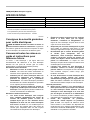
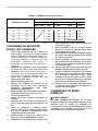
USE PROPER EXTENSION CORD. Make sure your
extension cord is in good condition. When using an
extension cord, be sure to use one heavy enough to
carry the current your product will draw. An undersized
cord will cause a drop in line voltage resulting in loss of
power and overheating. Table 1 shows the correct size
to use depending on cord length and nameplate ampere
rating. If in doubt, use the next heavier gage. The
smaller the gage number, the heavier the cord.
Table 1: Minimum gage for cord
Ampere Rating
Volts
Total length of cord in feet
More Than Not More Than
120V 25 ft. 50 ft. 100 ft. 150 ft.
AWG
06
6
10
12
10
12
16
18
18
16
14
16 16 14
1416
16
12
14
12
12
Not Recommended
220V - 240V 50 ft. 100 ft. 200 ft. 300 ft.
000300
GEB019-4
TRIMMER SAFETY WARNINGS
1.
Hold power tool by insulated gripping surfaces,
because the cutter may contact its own cord.
Cutting a "live" wire may make exposed metal parts
of the power tool "live" and shock the operator.
2. Use clamps or another practical way to secure
and support the workpiece to a stable
platform.Holding the work by your hand or
against the body leaves it unstable and may lead
to loss of control.
3. Wear hearing protection during extended
period of operation.
4. Handle the bits very carefully.
5. Check the bit carefully for cracks or damage
before operation. Replace cracked or
damaged bit immediately.
6. Avoid cutting nails. Inspect for and remove all
nails from the workpiece before operation.
7. Hold the tool firmly.
8. Keep hands away from rotating parts.
9. Make sure the bit is not contacting the
workpiece before the switch is turned on.

4
10. Before using the tool on an actual workpiece,
let it run for a while. Watch for vibration or
wobbling that could indicate improperly
installed bit.
11. Be careful of the bit rotating direction and the
feed direction.
12. Do not leave the tool running. Operate the tool
only when hand-held.
13. Always switch off and wait for the bit to come
to a complete stop before removing the tool
from workpiece.
14. Do not touch the bit immediately after
operation; it may be extremely hot and could
burn your skin.
15. Do not smear the tool base carelessly with
thinner, gasoline, oil or the like. They may
cause cracks in the tool base.
16. Use bits of the correct shank diameter suitable
for the speed of the tool.
17. Some material contains chemicals which may
be toxic. Take caution to prevent dust
inhalation and skin contact. Follow material
supplier safety data.
18. Always use the correct dust mask/respirator
for the material and application you are
working with.
SAVE THESE INSTRUCTIONS.
WARNING:
DO NOT let comfort or familiarity with product
(gained from repeated use) replace strict adherence
to safety rules for the subject product. MISUSE or
failure to follow the safety rules stated in this
instruction manual may cause serious personal
injury.
USD201-2
Symbols
The followings show the symbols used for tool.
・ volts
・ amperes
・ hertz
・ alternating current
・ no load speed
・ Class II Construction
・ revolutions or reciprocation per minute
FUNCTIONAL DESCRIPTION
CAUTION:
• Always be sure that the tool is switched off and
unplugged before adjusting or checking function on
the tool.
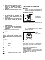
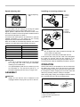
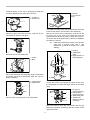
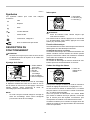
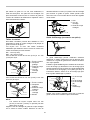
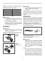
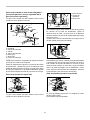
Adjusting bit protrusion
1
2
3
4
5
6
011834
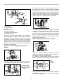
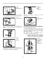
To adjust the bit protrusion, loosen the locking lever and
move the tool base up or down as desired by turning the
adjusting screw. After adjusting, tighten the locking lever
firmly to secure the tool base.
NOTE:
• When the tool is not secured even if the locking
lever is tightened, tighten the hex nut and then
tighten the locking lever.
Switch action
1
23
011836
CAUTION:
• Before plugging in the tool, always check to see
that the tool is switched off.
To start the tool, press the "ON ( I )" side of the switch.
To stop the tool, press the "OFF (O)" side of the switch.
Electronic function
The tool equipped with electronic function are easy to
operate because of the following features.
Constant speed control
Electronic speed control for obtaining constant speed.
Possible to get fine finish, because the rotating speed is
kept constant even under load condition.
Soft start
Soft-start feature minimizes start-up shock, and makes
the tool start smoothly.
1. Switch
2. OFF (O) side
3. ON ( I ) side
1. Bit protrusion
2. Tool base
3. Scale
4. Locking lever
5. Adjusting screw
6. Hex nut

5
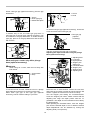
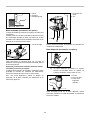
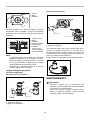
Speed adjusting dial
1
011835
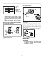
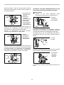
The tool speed can be changed by turning the speed
adjusting dial to a given number setting from 1 to 6.
Higher speed is obtained when the dial is turned in the
direction of number 6. And lower speed is obtained when it
is turned in the direction of number 1.
This allows the ideal speed to be selected for optimum
material processing, i.e. the speed can be correctly
adjusted to suit the material and bit diameter.
Refer to the table for the relationship between the number
settings on the dial and the approximate tool speed.
Number min
-1
1
2
3
4
5
6
10,000
30,000
12,000
17,000
22,000
27,000
011932
CAUTION:
• If the tool is operated continuously at low speeds
for a long time, the motor will get overloaded,
resulting in tool malfunction.
• The speed adjusting dial can be turned only as far
as 6 and back to 1. Do not force it past 6 or 1, or
the speed adjusting function may no longer work.
ASSEMBLY
CAUTION:
•
Always be sure that the tool is switched off and
unplugged before carrying out any work on the tool.
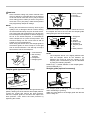
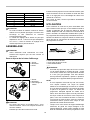
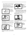
Installing or removing trimmer bit
1
2
3
011837
1
2
3
011987
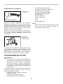
CAUTION:
• Do not tighten the collet nut without inserting a bit,
or the collet cone will break.
• Use only the wrenches provided with the tool.
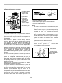
Insert the bit all the way into the collet cone and tighten
the collet nut securely with the two wrenches or by
pressing the shaft lock and using the provided wrench.
To remove the bit, follow the installation procedure in reverse.
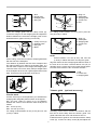
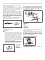
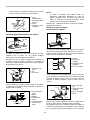
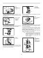
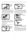
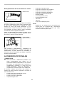
OPERATION
Set the tool base on the workpiece to be cut without the
bit making any contact. Then turn the tool on and wait
until the bit attains full speed. Move the tool forward over
the workpiece surface, keeping the tool base flush and
advancing smoothly until the cutting is complete.
When doing edge cutting, the workpiece surface should
be on the left side of the bit in the feed direction.
1
2
3
4
4
2
001984
1. Tighten
2. Loosen
3. Shaft lock
1. Tighten
2. Loosen
3. Hold
1. Speed adjusting
dial
1. Workpiece
2. Bit revolving direction
3. View from the top of the tool
4. Feed direction

6
CAUTION:
•
Since excessive cutting may cause overload of the
motor or difficulty in controlling the tool, the depth of
cut should not be more than 3 mm (1/8") at a pass
when cutting grooves. When you wish to cut grooves
more than 3 mm (1/8") deep, make several passes
with progressively deeper bit settings.
NOTE:
•
Moving the tool forward too fast may cause a poor
quality of cut, or damage to the bit or motor. Moving
the tool forward too slowly may burn and mar the cut.
The proper feed rate will depend on the bit size, the
kind of workpiece and depth of cut. Before beginning
the cut on the actual workpiece, it is advisable to
make a sample cut on a piece of scrap lumber. This
will show exactly how the cut will look as well as
enable you to check dimensions.
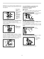
• When using the trimmer shoe, the straight guide or
the trimmer guide, be sure to keep it on the right
side in the feed direction. This will help to keep it
flush with the side of the workpiece.
1
2
3
4
001985
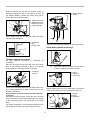
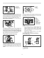
Templet guide (optional accessory)
011838
The templet guide provides a sleeve through which the bit
passes, allowing use of the trimmer with templet patterns.
Loosen the screws and remove the base protector.
Place the templet guide on the base and replace the
base protector. Then secure the base protector by
tightening the screws.
1
2
3
2
011839
Secure the templet to the workpiece. Place the tool on
the templet and move the tool with the templet guide
sliding along the side of the templet.
1
2
3
4
5
6
10mm (3/8")
7
011982
NOTE:
• The workpiece will be cut a slightly different size
from the templet. Allow for the distance (X)
between the router bit and the outside of the
templet guide. The distance (X) can be calculated
by using the following equation:
Distance (X) = (outside diameter of the templet guide -
router bit diameter) / 2
Straight guide (optional accessory)
011840
The straight guide is effectively used for straight cuts
when chamfering or grooving.
Attach the guide plate to the straight guide with the bolt
and the wing nut.
1. Straight bit
2. Base
3. Templet
4. Distance (X)
5. Workpiece
6. Templet guide
10
7. Base protector
1. Base protector
2. Screws
3. Screwdriver
1. Feed direction
2. Bit revolving
direction
3. Workpiece
4. Straight guide

7
1
2
3
4
001990
Attach the straight guide with the clamp screw (A).
Loosen the wing nut on the straight guide and adjust the
distance between the bit and the straight guide. At the
desired distance, tighten the wing nut securely.
1
2
3
4
011841
When cutting, move the tool with the straight guide flush
with the side of the workpiece.
If the distance (A) between the side of the workpiece and
the cutting position is too wide for the straight guide, or if
the side of the workpiece is not straight, the straight guide
cannot be used. In this case, firmly clamp a straight board
to the workpiece and use it as a guide against the trimmer
base. Feed the tool in the direction of the arrow.
A
011842
Circular work
Circular work may be accomplished if you assemble the
straight guide and guide plate as shown in the figures.
Min. and max. radius of circles to be cut (distance
between the center of circle and the center of bit) are as
follows:
Min.: 70 mm (2-3/4")
Max.: 221 mm (8-11/16")
For cutting circles between 70 mm (2-3/4") and 121 mm
(4-3/4") in radius.
1
2
3
4
5
001993
For cutting circles between 121 mm (4-3/4") and 221
mm (8-11/16") in radius.
1
2
3
4
5
001994
NOTE:
• Circles between 172 mm (6-3/4") and 186 mm
(7-5/16") in radius cannot be cut using this guide.
Align the center hole in the straight guide with the center of
the circle to be cut. Drive a nail less than 6 mm (1/4") in
diameter into the center hole to secure the straight guide.
Pivot the tool around the nail in clockwise direction.
1
2
3
011843
Trimmer guide (optional accessory)
011844
Trimming, curved cuts in veneers for furniture and the
like can be done easily with the trimmer guide. The
guide roller rides the curve and assures a fine cut.
Install the trimmer guide on the tool base with the clamp
screw (A). Loosen the clamp screw (B) and adjust the
1. Nail
2. Center hole
3. Straight guide
1. Wing nut
2. Guide plate
3. Straight guide
4. Center hole
5. Bolt
1. Wing nut
2. Guide plate
3. Straight guide
4. Center hole
5. Bolt
1. Clamp screw (A)
2. Straight guide
3. Wing nut
4. Base
1. Bolt
2. Guide plate
3. Straight guide
4. Wing nut

8
distance between the bit and the trimmer guide by
turning the adjusting screw (1 mm (3/64") per turn). At
the desired distance, tighten the clamp screw (B) to
secure the trimmer guide in place.
1
2
3
4
011845
When cutting, move the tool with the guide roller riding
the side of the workpiece.
1
2
3
001998
Tilt base (optional accessory)
Tilt base (optional accessory) is convenient for
chamfering.
Place the tool onto the tilt base and close the locking
lever at the desired protrusion of the bit. For desired
angle, tighten the clamping screws on its sides.
1
011993
Firmly clamp a straight board to the workpiece and use it
as a guide against the tilt base. Feed the tool in the
direction of the arrow.
Base protector removed from the tilt base (optional
accessory)
Mounting the base protector which has been removed
from the tilt base on the trimmer base allows the change
of the trimmer base from the round base to a square
base.
For another application, remove the base protector from
the tilt base by loosening and removing four screws.
1
2
011994
And then mount the base protector on the trimmer base.
Offset base (optional accessory)
012085
(1)
Offset base (optional accessory) is convenient
for work in a tight area such as a corner.
1
2
3
011858
Before installing the tool on the offset base, remove the
collet nut and collet cone by loosening the collet nut.
1
2
3
011985
1. Wrench
2. Pulley
3. Shaft lock
1. Pulley
2. Collet nut
3. Collet cone
1. Base protector
2. Screw
1. Clamping
screws
1. Workpiece
2. Bit
3. Guide roller
1. Clamp screw (A)
2. Adjusting screw
3. Clamp screw (B)
4. Trimmer guide

9
Install the pulley on the tool by pressing the shaft lock
and firmly tightening the pulley with a wrench.
1
2
011859
Place the collet cone and screw the collet nut on the
offset base as shown in the figure.
011860
Mount the tool on the offset base
1
2
011861
Put an end of the belt over the pulley using a screwdriver
and make sure that its entire belt width fits over the
pulley completely.
1
2
011862
Secure it with a locking lever on the offset base.
1
2
3
011992
To install the bit, fall the tool with the offset base on its side.
Insert the hex wrench into the hole in the offset base.
With the hex wrench held in that position, insert the bit into
the collet cone on the shaft of the offset base from the
opposite side and tighten the collet nut firmly with a wrench.
To remove the bit at replacement, follow the installation
procedure in reverse.
(2) Offset base (optional accessory) can also be
used with a trimmer base and a grip
attachment (optional accessory) for more
stability.
1
2
3
011934
Loosen the screws and remove the upper section from
the offset base. Put aside the upper section of the offset
base.
1
2
3
4
011935
Mount the trimmer base with four screws and the grip
attachment (optional accessory) with two screws on the
offset base plate.
1.
Bar type grip
(optional accessory)
2.
Grip attachment
(optional accessory)
3.
Offset base plate
4.
Trimmer base
assembly (optional
accessory)
1. Screws
2. Offset base
plate
3. Upper section o
f
the offset base
1. Wrench
2. Hex wrench
3. Bit
1. Locking lever
2. Offset base
1. Pulley
2. Belt
1. Collet nut
2. Collet cone

10
Screw a bar type grip (optional accessory) onto the grip
attachment.
1
2
3
011984
In another way of use, the knob type grip which is
removed from a plunge base (optional accessory) can
be installed on the grip attachment. To install the knob
type grip, place it on the grip attachment and secure it
with a screw.
011986
When using as a router only with a plunge
base (optional accessory)
CAUTION:
• When using as a router, hold the tool firmly with
both hands.
1
2
011855
To use the tool as a router, install the tool on a plunge
base (optional accessory) by pressing it down fully.
Either knob type grip or bar type grip (optional
accessory) can be used according to your work.
1
2
011856
To use the bar type grip (optional accessory), loosen the
screw and remove the knob type grip.
1
011857
And then screw the bar type grip on the base.
Adjusting the depth of cut when using the plunge
base (optional accessory)
1
2
3
4
5
6
7
8
011983
Place the tool on a flat surface. Loosen the lock lever
and lower the tool body until the bit just touches the flat
surface. Tighten the lock lever to lock the tool body.
Turn the stopper pole setting nut counterclockwise.
Lower the stopper pole until it makes contact with the
adjusting bolt. Align the depth pointer with the "0"
graduation. The depth of cut is indicated on the scale by
the depth pointer.
While pressing the fast-feed button, raise the stopper
pole until the desired depth of cut is obtained. Minute
depth adjustments can be obtained by turning the
adjusting knob (1 mm per turn).
1. Adjusting knob
2. Lock lever
3. Depth pointer
4. Stopper pole
setting nut
5. Fast-feed button
6. Stopper pole
7. Stopper block
8. Adjusting bolt
1. Bar type grip
(optional
accessory)
1. Screw
2. Knob
1. Plunge base
2. Grip
1. Screw
2. Knob type grip
3. Offset base plate

11
By turning the stopper pole setting nut clockwise, you
can fasten the stopper pole firmly.
Now, your predetermined depth of cut can be obtained
by loosening the lock lever and then lowering the tool
body until the stopper pole makes contact with the
adjusting hex bolt of the stopper block.
Always firmly hold the tool by both grip during operation.
Set the tool base on the workpiece to be cut without the
bit making any contact. Then turn the tool on and wait
until the bit attains full speed. Lower the tool body and
move the tool forward over the workpiece surface,
keeping the tool base flush and advancing smoothly until
the cutting is complete.
When doing edge cutting, the workpiece surface should
be on the left side of the bit in the feed direction.
1
2
3
4
4
2
001984
NOTE:
•
Moving the tool forward too fast may cause a poor
quality of cut, or damage to the bit or motor. Moving
the tool forward too slowly may burn and mar the cut.
The proper feed rate will depend on the bit size, the
kind of workpiece and depth of cut. Before beginning
the cut on the actual workpiece, it is advisable to
make a sample cut on a piece of scrap lumber. This
will show exactly how the cut will look as well as
enable you to check dimensions.
• When using the straight guide, be sure to install it
on the right side in the feed direction. This will help
to keep it flush with the side of the workpiece.
1
2
3
4
001985
Straight guide when using as a router (needed
to use with guide holder (optional accessory))
The straight guide is effectively used for straight cuts
when chamfering or grooving.
1
2
3
4
5
6
7
8
011988
Install the straight guide on the guide holder (optional
accessory) with the wing nut.
Insert the guide holder into the holes in the plunge base
and tighten the wing bolts. To adjust the distance
between the bit and the straight guide, loosen the wing
nut. At the desired distance, tighten the wing nut to
secure the straight guide in place.
Straight guide (optional accessory)
011848
The straight guide is effectively used for straight cuts
when chamfering or grooving.
1. Feed direction
2. Bit revolving
direction
3. Workpiece
4. Straight guide
1. Workpiece
2. Bit revolving direction
3. View from the top of the tool
4. Feed direction
1. Bolt
2. Guide holder
3. Wing nut
4. Bolt
5. Wing nut
6. Guide plate
7. Straight guide
8. Wing bolts

12
1
2
3
011849
To install the straight guide, insert the guide bars into the
holes in the plunge base. Adjust the distance between the
bit and the straight guide. At the desired distance, tighten
the wing bolts to secure the straight guide in place.
When cutting, move the tool with the straight guide flush
with the side of the workpiece.
A
011850
If the distance (A) between the side of the workpiece and
the cutting position is too wide for the straight guide, or if
the side of the workpiece is not straight, the straight guide
cannot be used. In this case, firmly clamp a straight board
to the workpiece and use it as a guide against the router
base. Feed the tool in the direction of the arrow.
Templet guide (optional accessory)
011851
The templet guide provides a sleeve through which the
bit passes, allowing use of the tool with templet patterns.
To install the templet guide, loosen the screws on the
tool base, insert the templet guide and then tighten the
screws.
12
3
011852
Secure the templet to the workpiece. Place the tool on
the templet and move the tool with the templet guide
sliding along the side of the templet.
1
2
3
4
5
6
7
003695
NOTE:
• The workpiece will be cut a slightly different size
from the templet. Allow for the distance (X)
between the bit and the outside of the templet
guide. The distance (X) can be calculated by using
the following equation:
Distance (X) = (outside diameter of the templet
guide - bit diameter) / 2
Dust nozzle sets (optional accessory)
For the trimmer base
1
2
3
011989
1. Bit
2. Base
3. Templet
4. Workpiece
5. Distance (X)
6. Outside
diameter of the
templet guide
7. Templet guide
1. Screw
2. Base
3. Templet
1. Guide bar
2. Wing bolt
3. Straight guide
1. Dust nozzle
2. Thumb screw
3. Trimmer base

13
For the plunge base
1
2
011853
Use the dust nozzle for dust extraction. Install the dust
nozzle on the tool base using the thumb screw so that
protrusion on the dust nozzle fit to the notch in the tool
base.
Then connect a vacuum cleaner to the dust nozzle.
011854
MAINTENANCE
CAUTION:
•
Always be sure that the tool is switched off and
unplugged before attempting to perform
inspection or maintenance.
•
Never use gasoline, benzine, thinner, alcohol or
the like. Discoloration, deformation or cracks may
result.
Replacing carbon brushes
1
001145
Remove and check the carbon brushes regularly.
Replace when they wear down to the limit mark. Keep
the carbon brushes clean and free to slip in the holders.
Both carbon brushes should be replaced at the same
time. Use only identical carbon brushes.
Use a screwdriver to remove the brush holder caps.
Take out the worn carbon brushes, insert the new ones
and secure the brush holder caps.
1
2
011846
To maintain product SAFETY and RELIABILITY, repairs,
any other maintenance or adjustment should be
performed by Makita Authorized or Factory Service
Centers, always using Makita replacement parts.
OPTIONAL ACCESSORIES
CAUTION:
• These accessories or attachments are
recommended for use with your Makita tool
specified in this manual. The use of any other
accessories or attachments might present a risk of
injury to persons. Only use accessory or
attachment for its stated purpose.
If you need any assistance for more details regarding
these accessories, ask your local Makita Service Center.
• Straight & groove forming bits
• Edge forming bits
• Laminate trimming bits
• Straight guide assembly
• Trimmer guide assembly
• Trimmer base assembly
• Tilt base assembly
• Plunge base assembly
• Offset base assembly
1. Screwdriver
2. Brush holder
cap
1. Limit mark
1. Dust nozzle
2. Thumb screw

14
• Templet guide
• Collet cone 1/4"
• Collet cone 3/8"
• Wrench 13
• Wrench 22
• Dust nozzle set
NOTE:
• Some items in the list may be included in the tool
package as standard accessories. They may differ
from country to country.
MAKITA LIMITED ONE YEAR WARRANTY
Warranty Policy
Every Makita tool is thoroughly inspected and tested
before leaving the factory. It is warranted to be free of
defects from workmanship and materials for the period
of ONE YEAR from the date of original purchase.
Should any trouble develop during this one year period,
return the COMPLETE tool, freight prepaid, to one of
Makita’s Factory or Authorized Service Centers. If
inspection shows the trouble is caused by defective
workmanship or material, Makita will repair (or at our
option, replace) without charge.
This Warranty does not apply where:
IN NO EVENT SHALL MAKITA BE LIABLE FOR ANY
INDIRECT, INCIDENTAL OR CONSEQUENTIAL
DAMAGES FROM THE SALE OR USE OF THE
PRODUCT. THIS DISCLAIMER APPLIES BOTH
DURING AND AFTER THE TERM OF THIS
WARRANTY.
MAKITA DISCLAIMS LIABILITY FOR ANY IMPLIED
WARRANTIES, INCLUDING IMPLIED WARRANTIES
OF "MERCHANTABILITY" AND "FITNESS FOR A
SPECIFIC PURPOSE," AFTER THE ONE YEAR TERM
OF THIS WARRANTY.
This Warranty gives you specific legal rights, and you
may also have other rights which vary from state to
state. Some states do not allow the exclusion or
limitation of incidental or consequential damages, so
the above limitation or exclusion may not apply to you.
Some states do not allow limitation on how long an
implied warranty lasts, so the above limitation may not
apply to you.
repairs have been made or attempted by others:
repairs are required because of normal wear and
tear:
the tool has been abused, misused or improperly
maintained:
alterations have been made to the tool.
EN0006-1
Page is loading ...
Page is loading ...
Page is loading ...
Page is loading ...
Page is loading ...
Page is loading ...
Page is loading ...
Page is loading ...
Page is loading ...
Page is loading ...
Page is loading ...
Page is loading ...
Page is loading ...
Page is loading ...
Page is loading ...
Page is loading ...
Page is loading ...
Page is loading ...
Page is loading ...
Page is loading ...
Page is loading ...
Page is loading ...
Page is loading ...
Page is loading ...
Page is loading ...
Page is loading ...
Page is loading ...
Page is loading ...
Page is loading ...
Page is loading ...
Page is loading ...
Page is loading ...
Page is loading ...

48
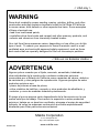
Some dust created by power sanding, sawing, grinding, drilling, and other
construction activities contains chemicals known to the State of California
to cause cancer, birth defects or other reproductive harm. Some examples
of these chemicals are:
• lead from lead-based paints,
• crystalline silica from bricks and cement and other masonry products, and
• arsenic and chromium from chemically-treated lumber.
Your risk from these exposures varies, depending o n how often you do this
type of work. To reduce your exposure to these chemicals: work in a well
ventilated area, and work with approved safety equipment, such as those
dust masks that are specially designed to filter out microscopic particles.
WARNING
< USA only >
ADVERTENCIA
Algunos polvos creados por el lijado, aserrado, esmerilado, taladrado y
otras actividades de la construcción contienen sustancias químicas
reconocidas por el Estado de California como causantes de cáncer, defectos
de nacimiento y otros peligros de reproducción. Algunos ejemplos de estos
productos químicos son:
• plomo de pinturas a base de plomo,
• sílice cristalino de ladrillos y cemento y otros productos de albañilería, y
• arsénico y cromo de maderas tratadas químicamente.
El riesgo al que se expone varía, dependiendo de la frecuencia con la que
realice este tipo de trabajo. Para reducir la exposición a estos productos
químicos: trabaje en un área bien ventilada y póngase el equipo de seguridad
indicado, tal como las máscaras contra polvo que están especialmente
diseñadas para filtrar partículas microscó
picas.
< Sólo en los Estados Unidos >
Makita Corporation
3-11-8, Sumiyoshi-cho,
Anjo, Aichi 446-8502 Japan
www.makita.com
885025-938
-
 1
1
-
 2
2
-
 3
3
-
 4
4
-
 5
5
-
 6
6
-
 7
7
-
 8
8
-
 9
9
-
 10
10
-
 11
11
-
 12
12
-
 13
13
-
 14
14
-
 15
15
-
 16
16
-
 17
17
-
 18
18
-
 19
19
-
 20
20
-
 21
21
-
 22
22
-
 23
23
-
 24
24
-
 25
25
-
 26
26
-
 27
27
-
 28
28
-
 29
29
-
 30
30
-
 31
31
-
 32
32
-
 33
33
-
 34
34
-
 35
35
-
 36
36
-
 37
37
-
 38
38
-
 39
39
-
 40
40
-
 41
41
-
 42
42
-
 43
43
-
 44
44
-
 45
45
-
 46
46
-
 47
47
-
 48
48


Ask a question and I''ll find the answer in the document
Finding information in a document is now easier with AI
in other languages
- français: Makita RT0701C Manuel utilisateur
- español: Makita RT0701C Manual de usuario