KNOVA KN M-2508RC Owner's manual
- Category
- Mitre saws
- Type
- Owner's manual

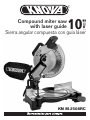
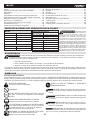
KN M-2508RC
Compound miter saw
with laser guide
10
”
(254 mm)
Sierra angular compuesta con guía láser

Table of contents ................................................................. 1
Product specications KN M-2508RC ................................ 1
Warnings ............................................................................. 1
Symbols .............................................................................. 1
Power tool safety ................................................................ 2
Compound miter saw safety ............................................... 3
Electrical requirements and safety ...................................... 3
Accessories and attachments ............................................. 4
Tools needed for assembly ................................................. 5
Carton contents .................................................................. 5
Know your compound miter saw ........................................ 6
Glossary of terms .............................................................. 7
Assembly ........................................................................... 7
Adjustments ..................................................................... 11
Operation ........................................................................... 14
Crown molding chart .......................................................... 19
Maintenance ...................................................................... 20
Troubleshooting guide ....................................................... 21
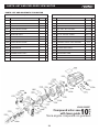
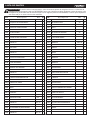
Parts list ............................................................................ 22
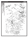
Exploded view .................................................................... 23
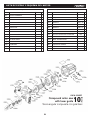
Parts list and exploded view motor ................................... 24
PRODUCT SPECIFICATIONS KN M-2508RC
TABLE OF CONTENTS
1
WARNINGS
Some dust created by power sanding, sawing, grinding, drilling and other construction activities contains
chemicals known to the state of California to cause cancer, birth defects or other reproductive harm. Some examples
of these chemicals are:
• Lead from lead-based paints,
• Crystalline silica from bricks and cement and other masonry products, and
• Arsenic and chromium from chemically-treated lumber.
Your risk from these exposures varies, depending on how often you do this type of work. To reduce your exposure to these chemi-
cal: work in a well ventilated area, and work with approved safety equipment, such as those dust masks that are specially designed
to ter out microscopic particles.
WARNING
SYMBOLS
WARNING ICONS
Your power tool and its Operator’s Manual may contain “WARNING ICONS” (a picture symbol intended to alert you to, and/or in-
struct you how to avoid, a potentially hazardous condition). Understanding and heeding these symbols will help you operate your tool
better a. safer. Shown below are some of the symbols you may see.
SAFETY ALERT: Precautions that involve your safety.
PROHIBITION
WEAR EYE PROTECTION: Always wear safety
goggles or safety glasses with side shields.
READ AND UNDERTAND
OPERATOR’S MANUAL
: To
reduce the risk of injury, user and all bystanders must
read understand
Operator’s Manual
before using this
product.
KEEP HANDS AWAY FROM BLADE: Failure to keep
your hands away from the blade will result in serious
personal injury.
SUPPORT AND CLAMP WORK
DANGER
DANGER: Indicates an inminently hazardous
situation which, if not avoided, will result in death or
serious injury.
WARNING
WARNING: Indicates a potentially hazardous
situation which, if not avoided, could result in dead or
serious injury.
CAUTION
CAUTION: Indicates a potentially hazardous
situation which, if not avoided, may result in minor or
moderate injury.
CAUTION
CAUTION: Used without the safety alert symbol indi-
cates a potentially hazardous situation which, if not avoided,
may result in property damage.
WEAR RESPIRATORY AND HEARING PROTEC-
TION: Always wear respiratory and hearing protection.
MOTOR
Power Source:
120V AC, 60Hz, 15 Amp
Speed (no load):
4,800 RPM (No load)
Electric Brake: Yes
Double insulared:
No
BLADE
Diameter: 10 in.
Arbor: 5/8 in.
MITER SAW
Rotating Table:
Miter Detent Stops:
0, 15, 22.5, 31.6, 45º R & L
Bevel Positive Stops:
0, 45º L
CUTTING CAPACITY
Crosscut: 2-5/8 in. x 5-1/2 in.
Miter 45° R & L: 2-5/8 in. × 3-7/8 in.
Bevel 45º L: 1-1/2 in. x 5-1/2 in.
45° Miter and 45° Bevel:
1-1/2 in. x 3-7/8 in.
Crow molding nested:
6-5/8 in.
Base molding against fence:
4-7/8 in.
WARNING
To avoid electrical
hazards, re hazards or damage to
the tool, use proper circuit protection. This
tool is wired at the factory for 110-120 Volt
operation. It must be connected to a 110-
120 Volt / 15 Ampere time delay fuse or
circuit breaker. To avoid shock or re, re-
place power cord immediately if it is worn,
cut or damaged in any way.
Before using your tool, it is critical that you
read and understand these safety rules.
Failure to follow these rules could result in
serious injury to you or damage to the tool.

GENERAL SAFETY INSTRUCTIONS BEFORE
USING THIS POWER TOOL
Safety is a combination of common sense, staying alert and
knowing how to use your power tool.
2
POWER TOOL SAFETY
WARNING
To avoid mistakes that could cause serious
injury, do not plug the tool in until you have read and
understood the following.
1. READ and become familiar with the entire
Opera-
tor’s Manual
. LEARN the tool’s application, limitations
and possible hazards.
2. KEEP GUARDS IN PLACE and in working order.
3. REMOVE ADJUSTING KEYS AND WRENCHES. Form
the habit of checking to see that keys and adjusting
wrenches are removed from the tool before turning ON.
4. KEEP WORK AREA CLEAN. Cluttered areas and benches
invite accidents.
5. DO NOT USE IN DANGEROUS ENVIRONMENTS. Do
not use power tools in damp locations, or expose them to
rain or snow. Keep work area well lit.
6. KEEP CHILDREN AWAY. All visitors and bystanders
should be kept a safe distance from work area.
7. MAKE WORKSHOP CHILD PROOF with padlocks,
master switches or by removing starter keys.
8. DO NOT FORCE THE TOOL. It will do the job better and
safer at the rate for which it was designed.
9. USE THE RIGHT TOOL. Do not force the tool or an
attachment to do a job for which it was not designed.
10. USE PROPER EXTENSION CORDS. Make sure your
extension cord is in good condition. When using an extension
cord, be sure to use one heavy enough to carry the current
your product will draw. An undersized cord will result in a
drop in line voltage and in loss of power which will cause
the tool to overheat. The table on page 4 shows the cor-
rect size to use depending on cord length and nameplate
ampere rating. If In doubt, use the next heavier gauge.
The smaller the gauge number, the heavier the cord.
11. WEAR PROPER APPAREL. Do not wear loose clothing,
gloves, neckties, rings, bracelets or other jewelry which
may get caught in moving parts. Nonslip footwear is
recommended. Wear protective hair covering to contain
long hair.
12. ALWAYS WEAR EYE PROTECTION. Any power
tool can throw foreign objects into the eyes and
could cause permanent eye damage. ALWAYS
wear Safety Goggles (not glasses) that comply
with ANSI Safety standard Z87.1. Everyday
eyeglasses have only impact–resistant lenses.
They ARE NOT safety glasses.
13. WEAR A FACE MASK OR DUST MASK. Sawing
operation produces dust.
14. SECURE WORK. Use clamps or a vise to hold work
when practical. It is safer than using your hand
and it frees both hands to operate the tool.
15. DISCONNECT TOOLS FROM POWER SOURCE before
servicing, and when changing accessories such as blades,
bits and cutters.
16. REDUCE THE RISK OF UNINTENTIONAL STARTING.
Make sure switch is in the OFF position before plugging
the tool in.
17. USE RECOMMENDED ACCESSORIES. Consult this
Operator’s Manual for recommended accessories. The
use of improper accessories may cause risk of injury
to yourself or others.
18. NEVER STAND ON THE TOOL. Serious injury could
occur if the tool is tipped or if the cutting tool is
unintentionally turn on.
19. CHECK FOR DAMAGED PARTS. Before further use of
the tool, a guard or other part that is damaged should be
carefully checked to determine that it will operate
properly and perform its intended function – check for
alignment of moving parts, binding of moving parts,
breakage of parts, mounting and any other conditions
that may affect its operation. A guard or other part that is
damaged should be properly repaired or replaced.
20. NEVER LEAVE THE TOOL RUNNING UNATTENDED.
TURN THE POWER “OFF”. Do not walk away from a
running tool until the grinding wheels come to a complete
stop and the tool is unplugged from the power source.
21. DO NOT OVERREACH. Keep proper footing and balance
at all times.
22. MAINTAIN TOOLS WITH CARE. Keep tools sharp and
clean for best and safest performance. Follow
instructions for lubricating and changing accessories.
23. DO NOT use power tool in presence of ammable liquids
or gases.
24. DO NOT operate the tool if you are under the inuence of
any drugs, alcohol or medication that could affect your
ability to use the tool properly.
NOTE: Glasses or goggles not in compliance with ANSI Z87.1
could seriously injure you when they break.
26. WEAR HEARING PROTECTION to reduce the
risk of induced hearing loss.
DANGER
27. People with devices electronic devices
such as pacemakers should consult their physician(s)
before using this product. The operation of electrical
equipment in the vicinity of a pacemaker placed in the
heart may cause interference or pacemaker failure.
WARNING
25. Dust generated from certain materials
can be hazardous to your health. Always operate saw
in well-ventilated area and provide for proper dust
removal.

3
COMPOUND MITER SAW SAFETY
SPECIFIC SAFETY INSTRUCTIONS FOR THIS
COMPOUND MITER SAW
1. DO NOT USE THIN KERF BLADES they can deect and
contact guard and can cause possible injury to the operator.
2. DO NOT operate the miter saw until it is completely
assembled and installed according to these instructions.
3. IF YOU ARE NOT thoroughly familiar with the operation
of miter saws, seek guidance from your supervisor,
instructor or other qualied person.
4. ALWAYS hold the work rmly against the fence and
table. DO NOT perform any operation free hand
(use clamp wherever possible).
5. KEEP HANDS out of the path of the saw blade. If the
workpiece you are cutting would cause your hands to be
within 6-3/4 in. of the saw blade, the workpiece should
be clamped in place before making the cut.
6. BE SURE the blade is sharp, runs freely and is free
of vibration.
7. ALLOW the motor to come up to full speed before
starting a cut.
8. KEEP THE MOTOR AIR SLOTS CLEAN and free
of chips or dust.
9. ALWAYS MAKE SURE all handles are tight before cutting,
even if the table is positioned in one of the positive stops.
10. BE SURE both the blade and the collar are clean and the
arbor bolt is tightened securely.
11. USE only blade collars specied for your saw.
12. NEVER use blades larger in diameter than 10 inches.
13. NEVER apply lubricants to the blade when it is running.
14. ALWAYS check the blade for cracks or damage before
operation. Replace a cracked or damaged blade
immediately.
15. NEVER use blades recommended for operation
at less than 4800 RPM.
16. ALWAYS keep the blade guards in place and
use at all times.
17. NEVER reach around the saw blade.
18. MAKE SURE the blade is not contacting the workpiece
before the switch is turned ON.
19. IMPORTANT: After completing the cut, release the
trigger and wait for the blade to stop before returning the
saw to the raised position.
20. MAKE SURE the blade has come to a complete stop
before removing or securing the workpiece, changing
the workpiece angle or changing the angle of the blade.
21. NEVER cut metals or masonry products with this tool.
This miter saw is designed for use on wood and
wood-like products.
22. NEVER cut small pieces. If the workpiece being cut may
lead your hand or ngers to be within 6-3/4 in. of the saw
blade, the workpiece is too small.
23. PROVIDE adequate support to the sides of the saw table
for long work pieces.
24. NEVER use the miter saw in an area with ammable
liquids or gases.
25. NEVER use solvents to clean plastic parts. Solvents could
possibly dissolve or otherwise damage the material.
26. SHUT OFF the power before servicing or adjusting
the tool.
27. DISCONNECT the saw from the power source and clean
the machine when nished using.
28. MAKE SURE the work area is clean before leaving
the machine.
29. SHOULD any part of your miter saw be missing,
damaged, or fail in any way, or any electrical component
fail to perform properly, lock the switch and remove the
plug from the power supply outlet. Replace missing,
damaged, or failed parts before resuming operation.
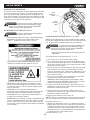
ELECTRICAL REQUIREMENTS AND SAFETY
GROUNDING INSTRUCTIONS
IN THE EVENT OF A MALFUNCTION OR BREAKDOWN,
grounding provides a path of least resistance for electric
currents and reduces the risk of electric shock. This tool is
equipped with an electrical cord that has an equipmentground-
ing conductor and a grounding plug. The plug must be plugged
into a matching receptacle that is properly installed and
grounded in accordance with all local codes and ordinances.
DO NOT MODIFY THE PLUG PROVIDED.
If it will not t the receptacle, have the proper receptacle in-
stalled by a qualied electrician.
IMPROPER CONNECTION of the equipment grounding con-
ductor can result in risk of electric shock. The conductor with
the green insulation (with or without yellow stripes) is the
equipment grounding conductor. If repair or replacement of
the electrical cord or plug is necessary, do not connect the
equipment grounding conductor to a live terminal.
CHECK with a qualied electrician or service person if you do
not completely understand the grounding instructions, or if
you are not certain the tool is properly grounded.
USE only three-wire extension cords that have three-pronged
grounding plugs with three-pole receptacles that accept the
tool’s plug. Repair or replace damaged or worn cords imme-
diately.
GUIDELINES FOR EXTENSION CORDS
USE THE PROPER EXTENSION CORD. Make sure your
extension cord is in good condition. Use an extension cord
heavy enough to carry the current your product will draw. An
undersized cord will cause a drop in line voltage resulting in
loss of power, overheating and burning out of the motor. The
table on the right shows the correct size to use depending
on cord length and nameplate ampere rating. If in doubt, use
the next heavier gauge. The smaller the gauge number, the
heavier the cord.

4
ELECTRICAL REQUIREMENTS AND SAFETY
Make sure your extension cord is properly wired and in good
condition. Always replace a damaged extension cord or have
it repaired by a qualied technician before using it. Protect
your extension cords from sharp objects, excessive heat and
damp or wet areas.
Use a separate electrical circuit for your tool. This circuit must
not be less than #12 wire with a 20 A time-lag fuse or a #14
wire with a 15 A timelag fuse.
NOTE: When using an extension cord on a circuit with a #14
wire, the extension cord must not exceed 25 feet in length.
Before connecting the motor to the power line, make sure the
switch is in the off position and the electric current is rated
the same as the current stamped on the motor nameplate.
Running at a lower voltage will damage the motor. This tool is
intended for use on a circuit that has a receptacle like the one
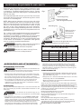
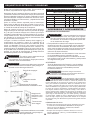
illustrated in Fig. 1.
Fig. 1 shows a three-pronged electrical plug and receptacle
that has a grounding conductor. If a properly grounded
receptacle is not available, an adapter (Fig. 2) can be used to
temporarily connect this plug to a two-contact grounded
receptacle. The adapter (Fig. 2) has a rigid lug extending from
it that MUST be connected to a permanent earth ground,
such as a properly grounded receptacle box.
ACCESSORIES AND ATTACHMENTS
RECOMMENDED ACCESSORIES
WARNING
In all cases, make certain the receptacle is
properly grounded. If you are not sure, have a
qualied electrician check the receptacle.
This tool is for indoor use only. Do not
expose to rain or use in damp locations.
Three-Pronged Plug
Two-Pronged
Receptacle
Fig. 1
Fig. 2
Grounding Prong
Properly Grounded
Three-Pronged Receptacle
WARNING
This tool must be grounded while in use to
protect the operator from electric shock.
MINIMUM GAUGE FOR EXTENSION CORDS (AWG)
(When using 120 volts only)
Ampere Rating Total length of Cord
More than
Not more than
25ft. 50ft. 100ft. 150ft.
0 6 18 16 16 14
6 10 18 16 14 12
10 12 16 16 14 12
12 16 14 12
Not Recommended
WARNING
• Use only accessories recommended for this
miter saw. Follow instructions that accompany accessories.
Use improper accessories may cause hazards.
• The use of any cutting tool except 10 in. saw blades which meet
the requirements under recommended accessories is prohibited.
Do not use accessories such as shaper cutters or dado sets.
Ferrous metal cutting and the use of abrasive wheels is prohibited.
• Do not attempt to modify this tool or create accessories not
recommended for use with this tool. Any such alteration or
modication is misuse and could result in a hazardous condition
leading to possible serious injury.
ACCESSORIES
Visit your Knova Hardware Department or see the Knova Power and
Hand Tool Catalog to purchase recommended accessories for this
power tool.
WARNING
• To avoid the risk of personal injury, do not
modify this power tool or use accessories not recommended
by Knova.
• Read warnings and conditions on your CARBIDE TIPPED SAW
BLADE. Do not operate the saw without the proper saw blade
guard in place. Carbide is a very hard but brittle material. Care
should be taken while mounting, using, and storing carbide tipped
blades to prevent accidental damage. Slight shocks, such as
striking the tip while handling, can seriously damage the blade.
Foreign objects in the workpiece, such as wire or nails, can also
Make sure this is
connected to a
known ground.
Grounding Lug
Adapter
BLADE INFORMATION
• Always use a crosscut blade that is designed for cutting across
grain. NEVER use Rip, Combination, Plywood, Dado or Abrasive
type saw blades at any time
• Always use a 10 in. diameter blade with either a 5/8 in. arbor hole,
speed rating must be at least 4800 RPM.
• Read and understand all instructions provided with each blade
before using on this miter saw.
There are two main materials used for saw blades; high-speed steel
(HSS) and carbide tipped (TCT). While the HSS blades are generally
less expensive than carbide tipped, TCT blades will stay sharper
longer than HSS. As a general rule the more teeth per inch (TPI) the
smoother the cut. Please read the information provided on the blade
for more details for their use.
General Purpose Wood Cutting: 24 - 40 TPI
Fine Woodworking Cutting: 60 - 80 TPI
Non-ferrous Metal Cutting: Use only special blades designed for
cutting this type of material.
Plastic Cutting:
Use only special blades designed for cutting plastic.
NOTE: When cutting non-ferrous or plastic, be sure to clean up
completely after each use. Take special care with metal shavings
after each cut, these can cause damage to the table top.
ALWAYS WEAR EYE PROTECTION.
WARNING
cause tips to crack or break off. Before using, always visually
examine the blade and tips for bent blade, cracks, breakage,
missing or loose tips, or other damage. Do not use if damage is
suspected. Failure to heed safety instructions and warnings can
result in serious bodily injury.

TOOLS NEEDED FOR ASSEMBLY
5
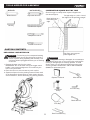
UNPACKING YOUR MITER SAW
WARNING
To avoid injury from unexpected starting
or electrical shock, do not plug the power cord into a
source of power during unpacking and assembly. This
cord must remain unplugged whenever you are working
on the saw.
1. Remove the miter saw from the carton.
IMPORTANT: Do not lift miter saw by the trigger switch
handle. It may cause misalignment. Lift machine by the
built-in carry hand hold.
2. Place the saw on a secure stationary work surface.
3. Separate all parts from the packing material. Check each
of the illustrations shown below to make certain all items
are accounted for, before discarding any packing material.
WARNING
If any part is missing or damaged, do not attempt to
assemble the miter saw, or plug in the power cord until the
missing or damaged part is correctly replaced. To avoid
electric shock, use only identical replacement parts when
servicing double insulated tools. Call 01-800-70-KNOVA
(56682) for replacement parts.
Miter Saw
Hold-Down
Clamp
Dust Bag
3 mm Hex Key
Miter Handle
Blade Wrench
Rear Extension Stay
SUPPLIED NOT SUPPLIED
Blade Wrench
Hex Key
Adjustable Wrench
Combination Square
Philips Screwdriver
Slotted Screwdriver
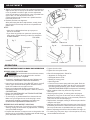
Draw light line on
board along this
edge.
Straight edge or a 3/4 in. board,
this edge must be perfectly straight.
Gap from untrue square
when ipped over.
COMBINATION SQUARE MUST BE TRUE
Should not gap or overlap when square is ipped over
(see dotted gure).
Operator’s Manual
CARTON CONTENTS

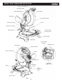
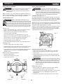
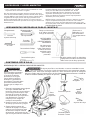
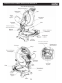
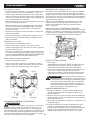
KNOW YOUR COMPOUND MITER SAW
Safety Lock-Off Button
Carrying Handle
Upper Blade Guard
Dust Bag
Hold-down Clamp
Table Insert
Battery Cover
Laser On/Off
Switch
ON/OFF
Trigger Switch
Miter Handle
Fence
Lower Blade Guard
Cover Plate
Positive Stop
Locking Lever
Bevel Lock Handle
Bevel Scale
Switch Handle
Exhaust Port
Rear
Extension
Stay
Hold-down
Latch
Laser Guide
Table
Motor
Miter Scale
Arbor Lock Button
Base
6

7
GLOSSARY OF TERMS
COMPOUND MITER SAW TERMS
AMPERAGE (AMPS) – A measure of the ow of electric cur-
rent. Higher ratings generally means the tool is suited for
heavier use.
ARBOR LOCK – Allows the user to keep the blade from rotat-
ing while tightening or loosening the arbor bolt during blade
replacement or removal.
BASE – Supports the table, holds accessories and allows for
workbench or leg set mounting.
BEVEL LOCKING HANDLE – Locks the miter saw at a de-
sired bevel angle.
BEVEL SCALE – To measure the bevel angle of the saw blade
0° to 45° left.
COVER PLATE SCREW – Loosen this screw and rotate the
plate for access to the blade arbor bolt.
FENCE – Helps to keep the workpiece from moving when
sawing. Scaled to assist with accurate cutting.
LOWER BLADE GUARD – Helps protect your hands from the
blade in the raised position, it retracts as the blade is lowered.
MITER HANDLE – Used to rotate the table, and to rotate the
saw to a right or left cutting position.
MITER SCALE – Measures the miter angle 0° to 45° left and right.
MOUNTING HOLES – To mount the miter saw to a stable
surface.
ON/OFF TRIGGER SWITCH – To start the tool, squeeze the
trigger. Release the trigger to turn off the miter saw.
POSITIVE STOP LOCKING LEVER – Locks the miter saw at
a preset positive stop for the desired miter angle.
HOLD-DOWN LATCH – Locks the miter saw in the lowered
position for compact storage and transportation.
SWITCH HANDLE – The switch handle contains the trigger
switch and the laser on/off switch. The blade is lowered into
the workpiece by pushing down on the handle. The saw will
return to its upright position when the handle is released.
WARNING LABELS – Read and understand for your own
safety. Make sure all labels are present on machine and legible.
WRENCH STORAGE – Convenient storage to prevent mis-
placing of the blade wrench.
WOODWORKING TERMS
ARBOR – The shaft on which a blade is mounted.
BEVEL CUT – An angle cut made through the face of the
workpiece.
COMPOUND CUT – A simultaneous bevel and miter cut.
CROSS CUT – A cut made across the width of the workpiece.
FREEHAND – Performing a cut without using a fence (guide),
hold down or other proper device to keep the workpiece from
twisting during the cutting operation.
GUM – A sticky sap from wood products.
HEEL – Misalignment of the blade.
KERF – The amount of material removed by blade cut.
MITER CUT – An angle cut made across the width of the
workpiece.
RESIN – A sticky sap that has hardened.
REVOLUTIONS PER MINUTE (RPM) – The number of turns
completed by a spinning object in one minute.
SAW BLADE PATH – The area of the workpiece or table top
directly in line with the travel of the blade or the part of the
workpiece which will be cut.
SET – The distance between two saw blade tips, bent outward
in opposite directions to each other. The further apart the tips
are, the greater the set.
WORKPIECE – The item being cut. The surfaces of a work-
piece are commonly referred to as faces, ends and edges.
ASSEMBLY
WARNING
To avoid injury, do not connect this miter
saw to the power source until it is completely
assembled and adjusted and you have read and
understood this Operator’s Manual.
WARNING
To avoid injury and damage to the saw,
transport or store the miter saw with the cutting head
locked in the down position. Never use the hold-down
latch to hold the cutting head in a down position for
cutting operations.
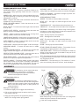
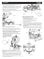
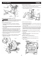
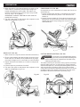
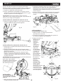
CUTTING HEAD (FIG. A)
Raising the Cutting Head
1. Push down slightly on the trigger switch handle (1).
2. Pull out the hold-down latch (2) and turn 90º to insert
into the short slot (3).
3. Raise the cutting head to the uppermost position.
NOTE: This cutting head is spring loaded.
Fig. A 1
5
2
4
3
Locking Cutting Head in Down Position
When transporting or storing the miter saw, the cutting head
should always be locked in the down position.
1. Push the cutting head down.

ASSEMBLY
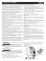
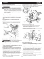
INSTALLING THE DUST BAG (FIG. C)
1. Squeeze the metal collar wings (2) of the dust bag (1).
2. Place the dust bag neck opening around the exhaust port
(3), and release the metal collar wings (2).
NOTE: To empty the dust bag, squeeze the metal collar
and remove from exhaust port. Open zipper on the
upperside of bag and empty into waste container.
IMPORTANT: Check frequently and empty bag before it
gets full. Do not use this saw
to cut and/or sand metals.
The hot chips or sparks may
ignite sawdust from the bag
material.
INSTALLING THE REAR EXTENSION STAY (FIG. D)
1. Loosen the extension stay locking screw (1) under the saw
base (2).
2. Place the rear extension stay (3) into the holes provided in
the miter saw base. Make sure the angle of stay is in the
down position (as shown in Fig. D) for maximum support.
3. Insert the extension stay locking screw back to hole and
tighten to hold the extension.
INSTALLING THE HOLD-DOWN
CLAMP ASSEMBLY (FIG. E, E-1)
1. Loosen the lock knob (1) from the rear side
of the saw base (2). (Fig. E).
2. Place the hold-down clamp (3) in one of
the mounting holes (4) as shown in Fig. E-1.
3. Tighten the lock knob (1).
NOTE: There are no knob to secure the clamp when place
in two front mounting holes. The clamp will secure itself to
the base when turning the clamp knob (5) to clamp the
workpiece. Do not use your other hand to hold the clamp
when tightening.
Only turn the clamp knob (5) to secure clamp to table. The
clamp will tilt at an angle and secure itself when tightened.
Fig. B
Fig. C
Fig. D
Fig. E
1
2
12
3
2
1
3
3
2
8
5
1
4
4
Fig. E-1
2. Pull the hold-down latch (2) out of the short slot (3) and
turn 90º to insert into the long slot (4).
IMPORTANT: To avoid damage, never carry the miter saw
by the switch handle, the cutting arm or the miter handle.
ALWAYS use the designated carrying handle (5).
INSTALLING THE MITER HANDLE (FIG. B)
1. Thread the miter handle (1) into the hole (2) located at the
front of the miter table.

9
ASSEMBLY
WARNING
Failure to unplug your tool could result in
accidental starting causing possible serious personal
injury.
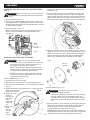
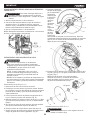
INSERTING AND REPLACING THE LASER BATTERIES
(FIG. F)
1. Open the battery cover (1).
2. Insert the two supplied AAA batteries in the case as per
the diagram below. If replacing the batteries, take out the
old batteries and replace with new AAA batteries. Dispose
off old batteries properly.
3. Close the battery cover (1).
NOTE: Replace the batteries with batteries that have a
rating of 1.5 volts (Number 4 series and AAA size or
equivalent).
WARNING
• Only use a 10-inch diameter blade.
• To avoid injury from an accidental start, make sure
the switch is in the OFF position and plug is not
connected to the power source outlet.
NOTE: The miter saw comes with the saw blade
already installed. Make sure the blade is installed
correctly and is tight before operating saw.
• NEVER cut metals or masonry products with this
tool. This miter saw is designed for use on wood
and wood-like products only.
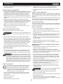
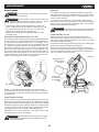
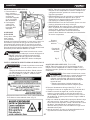
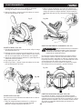
REMOVING OR INSTALLING THE BLADE
Removing Blade (Fig. G, H, I)
1. Unplug the saw from the outlet.
2. Raise the miter saw head to its most upright position.
3. Raise the lower blade guard (1) to the uppermost position.
(Fig. G)
4. While holding the lower blade guard (1), loosen the cover
plate screw (2) with a
Phillips screwdriver.
5. Rotate the cover
plate (3)
towards the
rear of the
tool to
expose the
arbor bolt
(4).
6. Place the
blade
wrench
over the
arbor
bolt (4).
7. Locate the arbor lock button (5) below the trigger switch
handle. (Fig. H)
8. Press the arbor lock button (5), holding it in rmly while
turning the blade wrench clockwise. This will engage the
arbor lock allowing the arbor bolt to be loosened with the
blade wrench. Continue to hold the arbor lock button (5),
while turning the wrench clockwise to loosen the arbor bolt.
9. Remove the arbor bolt (4), outer blade collar (6), and the
blade (7). Do not remove the inner blade collar (8). (Fig. I)
NOTE: Pay attention to the pieces removed, noting their
position and direction they face. Wipe the blade collars
clean of any sawdust before installing the new blade.
WARNING
Un-plug the miter saw before
changing/installing the blade.
Install a 10 in. blade with a 5/8 in. arbor hole, making
sure the rotation arrow on the blade matches the
clockwise rotation arrow on the upper guard, and the
blade teeth are pointing downward at the front of the
saw.
Installing Blade (Fig. G, H, I)
1. Place the blade (7) onto the arbor (9) and against the inner
blade collar (8). Place the outer blade collar (6) against
the blade onto the arbor. Thread the arbor bolt (4)
counterclockwise into the arbor (9). (Fig. I)
IMPORTANT: Make sure the ats of the blade collars are
engaged with the ats on the arbor shaft. Also, the at side
of the blade collar must be placed against the blade.
Fig. F
Fig. G
1
2
3
4
6
Fig. H
5
Fig. I
1
46
7
8
9
Do not
remove

ASSEMBLY
10
2. Place the blade wrench on the arbor bolt.
3. Press the arbor lock button (5), holding it in rmly while
turning the blade counterclockwise. When arbor lock
button engages, continue to press it in while tightening the
arbor bolt securely. (Fig. H).
4. Rotate the cover plate (3) back to its original position until
the slot in the cover plate engages with the cover plate
screw (2). While holding the lower blade guard, tighten the
screw with a Phillips screwdriver. (Fig. G).
NOTE: The lower blade guard must be raised to the upright
position to access the cover plate screw.
5. Lower the blade guard (1) and verify that the operation of
the guard does not bind or stick.
6. Be sure the arbor lock button (5) is released so the blade
turns freely by spinning the blade until the arbor lock
disengages. (Fig. H)
WARNING
• To avoid injury, never use the saw without
the cover plate secure in place. It keeps the arbor bolt
from falling out if it accidentally loosens, and helps
prevent the spinning blade from coming off the saw.
• Make sure the collars are clean and properly arranged.
Lower the blade into the table and check for any contact
with the metal base or the saw table.
WARNING
To avoid injury:
• Always unplug the saw to avoid accidental starting.
Remove all small pieces of material from the table
cavity before performing any cuts. The table insert
may be removed for this purpose, but always
reattach the table insert prior to performing a cutting
operation.
• Do not start the sliding compound miter saw without
checking for interference between the blade and table
insert. Damage could result to the blade, table insert or
turntable if blade strike occurs during the cutting operation.
1. To remove, loosen and remove the four screws (1) on the
table insert (2) with a Phillips screwdriver and remove the
insert.
2. To install, reposition the table insert (2), install the four
screws (1) and tighten.
REMOVING AND INSTALLING THE TABLE INSERT (FIG. J)
WARNING
To avoid injury from unexpected saw
movement:
• Before moving the saw, disconnect the power cord
from the outlet, and lock the cutting arm in the lower
position using the hold-down latch.
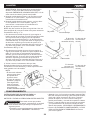
MOUNTING THE MITER SAW (FIG. K, L)
NOTE: The hold-down latch is for carrying or storing the tool.
It is not to be used for holding the saw while cutting. Lower
blade and press in hold-down latch to secure saw for
transport or storage.
• Never carry the miter saw by the power cord or by the
switch handle. Carrying the tool by the power cord could
cause damageto the insulation or wire connections
resulting in electric shock or re.
• To avoid injury from ying debris, do not allow visitors to
stand behind the saw.
• Place the saw on a rm, level work surface where there is
room for handling and properly supporting the workpiece.
• Support the saw on a level work surface.
• Bolt or clamp the saw to its support.
Place the saw in the desired location, either on a workbench
or recommended leg set. The base of the saw has four
mounting holes (10). (Fig. K)
Mounting instructions
1. For stationary use, place the saw in the desired location,
directly on a workbench where there is room for handling
and proper support of the workpiece. The base of the saw
has four mounting holes. Bolt the base of the miter saw (1)
to the work surface (5), using the fastening method as
shown in Fig K.
1. Miter saw base
2. Hex head bolt
3. Rubber washer
4. Flat washer
5. Workbench
6. Flat washer
7. Lock washer
8. Hex nut
9. Jam nut
NOTE: Mounting
hardware is not
included with this tool. Bolts, nuts, washers, and screws
must be purchased separately.
2. For portable use, place the saw on a 3/4 in. thick piece of
plywood. Bolt the base of the miter saw securely to the
plywood using the mounting holes on the base. Use
C-clamps to clamp this mounting board to a stable work
surface at the worksite. (Fig. L)
Fig. J
Fig. K
1
2
2
3
4
1
5
6
78
9
10
10

ASSEMBLY
11
Hand Hold for
Transportation
3/4 inch
plywood
NOTE: If a miter saw stand is used, please follow all
instructions shown in that product’s instructions for proper
mounting.
ADJUSTMENTS
WARNING
To avoid injury from an accidental start,
make sure the switch is in the OFF position and the
plug is not connected to the power source outlet.
ADJUSTMENT INSTRUCTIONS
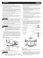
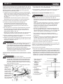
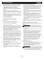
ADJUSTING FENCE SQUARENESS (FIG. M)
1. Loosen the three fence locking bolts (1).
2. Lower the cutting arm and lock in position.
3. Using a square, lay the heel of the square against the
blade, and the ruler agaist the fence (2) as shown. Check
to see if the fence is 90° to the blade.
4. If not, adjust fence 90° to the blade and tighten the fence
locking bolts.
CAUTION: If the saw has not been used recently, recheck
blade squareness to the fence and readjust if needed.
5. After fence has been aligned, using a scrap piece of wood,
make a cut at 90° then check squareness on the piece.
Readjust if necessary.
MITER SCALE (FIG. N)
The miter scale assists the user in setting the desired miter
angles from 45° left to 45° right. The miter saw table
has nine of the most common angle setttings with positive
stops at 0°, 15°, 22.5°, 31.6°, and 45°. These positive stops
position the blade at the desired angle quickly and accurately.
To Adjust the Angle:
1. Unlock the miter table by turning the miter handle (1)
counterclockwise.
2. Press down the positive stop locking lever (2) while holding
the miter handle, and rotate the table left or right to the
desired angle.
3. Release positive stop locking lever. Tighten miter handle.
4. If the desired angle is one of the nine positive stops,
release the positive stop locking lever, making sure the
lever snaps into position, and then secure by tightening the
miter handle.
5. If the miter angle desired is not one of the nine positive
stops, simply lock the miter table into position by turning
the miter handle in the clockwise direction.
To Adjust the Indicator:
1. Adjust the indicator (3) to the 0° mark on the miter scale
(4) to position the miter table.
2. Release positive stop locking lever (2). Tighten miter
handle (1).
WARNING
To avoid injury from unexpected starting or
electrical shock, turn the switch OFF and remove the
power cord from the power source.
NOTE: Before each cutting operation,
check the position of the blade to make sure it does not
contact any metal surface. If the blade contacts any
metal surface, the depth of travel must be adjusted.
CUTTING ARM TRAVEL
Cutting Arm Downward Travel Adjustment (Fig. O)
1. Lower the blade as far as possible.
2. Loosen the locknut (1).
3. Turn the adjustment bolt (2) out (counterclockwise) to
decrease the cutting depth or in (clockwise) to increase the
cutting depth.
4. Carefully rotate the blade manually to check for contact.
Avoid touching blade points or edges.
5. Repeat until adjusted properly, and tighten the locknut (1)
to secure the adjustment bolt (2) into position.
Fig. L
Fig. M
Fig. N
12
1
432
1

ADJUSTMENTS
12
WARNING
To avoid injury from unexpected starting or
electrical shock, make sure the trigger is released and
remove the power cord from the power source.
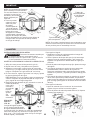
BEVEL STOP ADJUSTMENT (FIG. P, Q)
90° Bevel Adjustment (Fig. P)
1. Loosen bevel lock handle (1) and tilt the cutting arm
completely to the right. Tighten the bevel lock handle.
Lower blade.
2. Place a combination square (2) on the miter table with the
ruler against the table and the heel of the square against
the saw blade.
3. If the blade is not 90° square with the miter table, loosen
the bevel lock handle, tilt the cutting head completely to
the left, loosen the locknut (4) on the bevel angle
adjustment bolt (3) and use a 13 mm wrench to adjust the
bolt (3) in or out to increase or decrease the bevel angle.
4. Tilt the cutting arm back to the right at 90° bevel and
recheck for alignment.
5. Repeat steps 1 through 4 if further adjustment is needed.
6. Tighten bevel lock handle (1) and locknut (4) when
alignment is achieved.
90° Bevel Indicator (Fig. Q)
1. When the blade is exactly 90° to the table, loosen the bevel
indicator screw (5) using a #2 Phillips screwdriver.
2. Adjust bevel indicator (6) to the “0” mark (7) on the bevel
scale and retighten the screw.
45° Bevel Adjustment (Fig. Q)
1. Unlock the bevel lock handle (1) and tilt the cutting arm as
far to the left as possible.
2. Using a combination square, check to see if the blade angle
is 45° to the table.
3. If the blade is not at 45° to the miter table, tilt the cutting
arm to the right, loosen the locknut (8) on the bevel angle
adjustment bolt (9) and use a 13 mm wrench to adjust the
bolt (9) in or out to increase or decrease the bevel angle.
4. Tilt the cutting arm to the left to 45° bevel and recheck
for alignment.
5. Repeat steps 1 through 4 until the blade is at 45° to the
miter table.
6. Tighten bevel lock handle (1) and locknut (8) when
alignment is achieved.
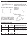
TURNING LASER GUIDE ON (FIG. R)
1. To turn laser on, press on/off rocker switch (1) to
“ON” position.
2. To turn laser off, press on/off rocker switch (1) to
“OFF” position.
Fig. O
Fig. P
Fig. Q
Fig. R
1
2
3
4
1
2
9
8
1
7
6
5
1

ADJUSTMENTS
ALIGNING THE LASER GUIDE
The laser line must always be correctly aligned with the blade
to ensure straight, even cutting. Your tool is equipped with
the Laser guide cutting guide using Class IIIa laser line. The
laser line will enable you to preview the saw blade path on the
stock to be cut before starting the miter saw. This laser guide
is powered by two AAA 1.5 volt batteries.
WARNING
To prevent injury, insert a padlock (not
provided) through the hole in the ON/OFF trigger
switch. Do not remove the lock from the ON/OFF
switch during any laser adjustments.
WARNING
• Laser is radiated when Laser guide is
turned on. Avoid direct eye contact.
AVOID DIRECT EYE CONTACT (FIG. S)
• Laser Warning Label: Max output <5mW Wavelength:
630-660nm, Complies with 21CFR 1040.10 and
1040. 11. CLASS IIIa Laser Product. (Fig. S)
• Laser Aperture Label: AVOID EXPOSURE: Laser
radiation is emitted from this aperture. (Fig. S)
• NOTE: All the adjustments for the operation of this
machine have been completed at the factory. Due to
normal wear and use, some occasional readjustments
may be necessary.
• CAUTION: Use of controls or adjustments or
performance of procedures other than those specied
herein may result in hazardous radiation exposure.
• CAUTION: The use of optical instruments with this
product will increase eye hazard.
• WARNING: Do not attempt to repair or disassemble the
laser. If unqualied persons attempt to repair this laser
product, serious injury may result. Any repair required
on this laser product should be performed by a qualied
service dealer.
LASER GUIDE ADJUSTMENT (FIG. T, U, V, W)
NOTE: All the adjustments for the operation of this machine
have been completed at the factory. Due to normal wear and
use, some occasional readjustments may be necessary.
WARNING
• To prevent injury, insert a padlock (not
provided) through the hole in the ON/OFF trigger
switch. Do not remove the lock from the ON/OFF
switch during any laser adjustments.
• Un-plug the miter saw before making any laser line
adjustments.
A. Checking Laser Line Alignment (Fig. T, U, V)
1. Set the saw to a 0° miter and 0° bevel setting.
2. Use a combination square to mark a 90° langled running
across the top and down the front of a board. This line will
serve as the pattern line (Fig. V) to adjust the laser. Place
the board on the saw table.
3. Carefully lower the saw head down to align the saw blade
with the pattern line. Position the saw blade to the left,
center or right side of the “pattern line” depending on your
preference for the laser line location. Lock board in place
with hold-down clamp.
4. Turn on the Laser guide. Your saw has been preset with
the laser line to the left side of the blade.
WARNING: When making laser line adjustments, keep
ngers away from the ON/OFF trigger switch to prevent
accidental starting and possible serious injury.
5. Looking at the front of the board, if the laser line is not
parallel to the “pattern line” please follow the instructions
listed below under Procedure A.
6. Looking at the top of the board, if the laser line is not
parallel to the “pattern line” please follow the instructions
listed below under Procedure B.
B. Adjusting the Position of the Laser Line
NOTE: There are two adjustment screws on the Laser guide.
Use a 3 mm hex wrench to make any needed adjustments.
Procedure A (Fig. U, V)
1. Slightly turn adjustment screw (1) to adjust the vertical
angle of laser line on the front of the board. If the laser line
is angled from left to right, turn the adjustment screw (1)
clockwise; If the laser line is angled right to left, turn the
adjustment screw (1) counterclockwise until the laser line
is parallel with the vertical pattern line.
Procedure B (Fig. U, W)
Fig. S
Laser
Aperture
Label
Laser
Warning
Label
13

ADJUSTMENTS
2. Slightly turn adjustment screw (2) to adjust the horizontal
angle of laser line on the top of the board. If the laser line
is out of parallel from left to right, turn the adjustment
screw (2) clockwise; If the laser line is out of parallel from
right to left, turn the adjustment screw (2)
counterclockwise until the laser line is parallel with the
horizontal pattern line.
3. Recheck the laser line alignment.
After performing the above adjustments, visually check
that both the front and top laser lines are parallel with
pattern line.
NOTE:
• Laser line is calibrated and set up to project to
the left of the blade.
• If you have any problem or questions concerning the
Laser guide, call the following number for assistance:
01-800-70-56682.
SAFETY INSTRUCTIONS FOR BASIC SAW OPERATION
BEFORE USING THE MITER SAW
WARNING
To avoid mistakes that could cause serious,
permanent injury, do not plug the tool in until the
following steps are completed:
• Completely assemble and adjust the saw, following the
instructions. (ASSEMBLY AND ADJUSTMENTS)
• Learn the use and function of the ON/OFF switch, lock-off
switch, upper and lower blade guards, hold-down latch,
bevel lock handle and cover plate screws.
• Review and understand all safety instructions and
operating procedures in this Operator’s Manual. (SAFETY
& OPERATIONS)
• Review the MAINTENANCE and TROUBLESHOOTING
GUIDE for your miter saw.
• To avoid injury or possible death from electrical shock:
Make sure your ngers do not touch the plug’s metal
prongs when plugging or unplugging your miter saw.
(ELECTRICAL EQUIREMENTS AND SAFETY)
OPERATION
BEFORE EACH USE INSPECT YOUR SAW.
• Disconnect the miter saw. To avoid injury from accidental
starting, unplug the saw before any adjustments, including
set-up and blade changes.
• Compare the direction of rotation arrow on the guard to the
direction arrow on the blade. The blade teeth should always
point downward at the front of the saw.
• Tighten the arbor bolt.
• Tighten the cover plate screw.
• Check for damaged parts. Check for:
• Alignment of moving parts
• Damaged electric cords
• Binding of moving parts
• Mounting holes
• Function of arm return spring and lower guard: Push the
cutting arm all the way down, then let it rise until it stops.
The lower guard should fully close. Follow instructions in
TROUBLESHOOTING GUIDE for adjustment if necessary.
• Other conditions that may affect the way the miter
saw works.
• Keep all guards in place, in working order and proper
adjustment. If any part of this miter saw is missing, bent,
damaged or broken in any way, or any electrical parts don’t
work, turn the saw off and unplug it.
• Replace bent, damaged, missing or defective parts before
using the saw again.
• Maintain tools with care. Keep the miter saw clean for best
and safest performance. Follow instructions for lubricating.
Do not put lubricants on the blade while it is spinning.
• Remove adjusting wrench from the tool before turning it on.
• To avoid injury from jams, slips, or thrown pieces, use only
recommended accessories.
Fig. U
Fig. T
TOP VIEW
Laser line
Blade
Cutting line
Workpiece
Cutting line
Laser line
Fig. V
Laser line
Counterclockwise
Pattem line
Clockwise
Fig. W
Laser line Pattem line
Counterclockwise Clockwise
14
2
1

OPERATION
15
• Check the dust bag before you work. Empty the bag if it is
more than half-full.
RECOMMENDED ACCESSORIES
• Consult the ACCESSORIES and ATTACHMENTS section of
this Operator’s Manual for recommended accessories. Follow
the instructions that come with the accessory. The use of
improper accessories may cause risk of injury to persons.
• Choose the correct 10 in. diameter blade for the material
and the type of cutting you plan to do. Do not use thin kerf
blades.
• Make sure the blade is sharp, undamaged and properly
aligned. With the saw unplugged, push the cutting arm all the
way down. Manually spin the blade and check for clearance.
Tilt the power-head to a 45° bevel and repeat the test.
• Make sure the blade and arbor collars are clean.
• Make sure all clamps and locks are tight and there is no
excessive play in any parts.
KEEP YOUR WORK AREA CLEAN
Cluttered areas and benches invite accidents.
WARNING
To avoid burns or other re damage, never
use the miter saw near ammable liquids, vapors, or
gases.
• Plan ahead to protect your eyes, hands, face and ears.
• Know your miter saw. Read and understand this Operator’s
Manual and labels afxed to this tool. Learn its application
and limitations as well as the specic potential hazards
peculiar to this tool. To avoid injury from accidental contact
with moving parts, do not do layout, assembly, or setup
work on the miter saw while any parts are moving.
• Avoid accidental starting, make sure the trigger switch is
disengaged before plugging the
miter
saw into a power outlet.
PLAN YOUR WORK
• Use the right tool. Don’t force a tool or attachment to do a
job it was not designed to do. Use a different tool for any
workpiece that can’t be held in a solidly braced, xed position.
CAUTION
This machine is not designed for cutting
masonry, masonry-like products, ferrous metals (steel,
iron, and iron-based metals.) Use this miter saw to cut
only wood, woodlike products, or non-ferrous metals.
Other material may shatter, bind the blade, or create
other dangers. Remove all nails that may be in the
workpiece to prevent sparking that could cause a re.
Remove dust bag when cutting non-ferrous metals.
DRESS FOR SAFETY
Any power tool can throw foreign objects into the
eyes. This can result in permanent eye damage.
Everyday eyeglasses have only impact resistant
lenses and are not safety glasses. Glasses or
goggles not in compliance with ANSI Z87.1 could
seriously injure you when they break.
• Do not wear loose clothing, gloves, neckties or jewelry
(rings, watches). They can get caught and draw you into
moving parts.
• Wear non-slip footwear.
• Tie back long hair.
• Roll long sleeves above the elbow.
USE EXTRA CAUTION WITH LARGE OR ODD SHAPED
WORKPIECES.
• Use extra supports (tables, sawhorses, blocks, etc.) for
workpieces large enough to tip.
• Never use another person as a substitute for a table
extension, or as an additional support for a workpiece that
is longer or wider than the basic miter saw table, or to help
feed, support, or pull the workpiece.
• Do not use this saw to cut small pieces. If the workpiece
being cut would cause your hand or ngers to be within
6-3/4 inches of the saw blade the workpiece is too small.
Keep hands and ngers out of the “no-hands zone” area
marked on the saw table.
• When cutting odd shaped workpieces, plan your work so it
will not bind in the blade and cause possible injury.
Molding, for example, must lie at or be held by a xture
or jig that will not let it move when cut.
• Properly support round material such as dowel rods, or
tubing, which have a tendency to roll when cut, causing
the blade to “bite”.
• Noise levels vary widely. To avoid possible hearing
damage, wear ear plugs when using any miter saw.
• For dusty operations, wear a dust mask along with safety
goggles.
INSPECT YOUR WORKPIECE
Make sure there are no nails or foreign objects in the part of
the workpiece being cut. Plan your work to avoid small pieces
that may bind, or that are too small to clamp and get a solid
grasp on.
Plan the way you will grasp the workpiece from start to nish.
Avoid awkward operations and hand positions. A sudden slip
could cause your ngers or hand to move into the blade.
DO NOT OVER-REACH
Keep good footing and balance. Keep your face and body to
one side, out of the line of a possible kickback. NEVER stand
in the line of the blade.
Never cut freehand:
• Brace your workpiece rmly against the fence and table
stop so it will not rock or twist during the cut.
• Make sure there is no debris between the workpiece and
the table or fence.
• Make sure there are no gaps between the workpiece, fence
and table that will let the workpiece shift after it is cut.
• Keep the cut off piece free to move sideways after it is cut
off. Otherwise, it could get wedged against the blade and
thrown violently.
• Only the workpiece should be on the saw table.
• Secure work. Use clamps or a vise to help hold the work
when it’s practical.
WARNING
To avoid injury, follow all applicable safety
instructions, when cutting non-ferrous metals:
• Use only saw blades specically recommended for
non-ferrous metal cutting.
• Do not cut metal workpieces that must be hand held. Clamp
workpieces securely.
• Cut non-ferrous metals only if you are under the
supervision of an experienced person and the dust bag has
been removed from the saw.

OPERATION
16
WHEN SAW IS RUNNING
WARNING
Do not allow familiarity from frequent use
of your miter saw to result in a careless mistake.
A careless fraction of a second is enough to cause a
severe injury.
Before cutting, if the saw makes an unfamiliar noise or vi-
brates, stop immediately. Turn the saw OFF. Unplug the saw.
Do not restart until nding and correcting the problem.
MAKING A BASIC CUT
WARNING
BODY AND HAND POSITION (Fig. X)
Never place hands near the cutting area. Proper positioning
of your body and hands when operating the miter saw will
make cutting easier and safer. Keep children away. Keep all
visitors at a safe distance from the miter saw. Make sure by-
standers are clear of the saw and workpiece. Don’t force the
saw. It will do the job better and safer at its designed rate.
Starting a cut:
• Place hands at least 6-3/4 in. away from the path of the
blade – out of the “no-hands zone” (1). (Fig. X)
• Hold workpiece rmly against the fence to prevent
movement toward the blade.
• Turn the Laser guide on for prealignment of your cut.
• With the power switch OFF, bring the saw blade down to
the workpiece to see the cutting path of the blade.
• Press in lock-off switch in trigger switch handle.
• Squeeze trigger switch to start saw.
• Lower blade into workpiece with a rm downward motion.
Finishing a cut:
• Hold the cutting arm in the down position.
• Release trigger switch and wait for all moving parts to stop
before moving your hands and raising the cutting arm.
• If the blade doesn’t stop within 7 seconds, unplug the saw
and follow the instructions in TROUBLESHOOTING
GUIDE section.
Before free the jammed material:
• Release trigger switch.
• Wait for all moving parts to stop.
• Unplug the miter saw.
Fig. X
6-3/4 in. 6-3/4 in.
TURNING SAW ON (FIG. Y)
To reduce the likelihood of accidental starting, a thumb acti-
vated lock-off switch is located on top of the switch handle.
The lock-off switch (1) must be pushed in before the trigger
switch (2) can be activated and the miter saw started.
BEFORE LEAVING THE SAW
• Never leave tool running unattended. Turn power OFF.
Wait for all moving parts to stop and unplug unit from
power source.
• Make workshop child- proof. Lock the shop. Disconnect
master switches. Store tool away from children and other
unqualied users.
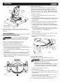
MITER CUT (FIG. Z)
1. When a miter cut is required, unlock the miter table by
turning the miter handle (1) counterclockwise.
2. While holding the miter handle, press down on the positive
stop locking lever (2) to disengage the positive stop
locking lever.
3. Rotate the miter table to the right or left with the miter
WARNING
For your convenience, your saw has
blade brake. The brake is not a safety device. Never
rely on it to replace the proper use of the guard on your
saw. If the blade doesn’t stop within approximately 7
seconds, wait for the blade to stop, unplug the saw and
contact Sears or another qualied service dealer.
BASIC SAW OPERATIONS
WARNING
To avoid injury from materials being thrown,
always unplug the saw to avoid accidental starting, and
remove small pieces of material from the table cavity.
The table insert may be removed for this purpose, but
always reattach the table insert prior to performing a
cutting operation.
NOTE: The miter saw is equipped with an electric blade brake.
When the trigger switch is released, the blade brake will stop
the blade within approximately 7 seconds.
NOTE: To make the ON/OFF trigger switch childproof. Insert
a padlock (not provided) through the hole (3) in the trigger
switch. Lock the tool’s switch to prevent children and other
unqualied users from turning the machine on.
Fig. Y
1
1
23

OPERATION
COMPOUND CUT (FIG. BB)
A compound cut is the combination of a miter and a bevel cut
simultaneously.
1. Loosen the bevel lock handle (1) and position the cutting
head at the desired bevel position. Lock the bevel lock
handle (1).
2. Loosen the miter handle (2). Press down the positive stop
locking lever (3) and position the table at the desired angle.
Release the positive stop locking lever (3) and lock the
miter handle (2).
WARNING
To avoid injury from materials being thrown,
always unplug the saw to avoid accidental starting and
remove small pieces of material from the table cavity
underlying the table insert.
CUTTING BOWED MATERIAL (FIG. CC)
The table insert may be removed for this purpose, but always
reattach table insert prior to performing a cutting operation.
A bowed workpiece (1) must be positioned against the fence
and secured with a hold-down clamp (2) as shown before
cutting. Do not position workpiece incorrectly or try to cut the
workpiece without the support of the fence. This will cause
the blade to bind and could result in personal injury.
21
Fig. AA
Fig. BB
Fig. CC
17
1
2
1
3
2
Fig. Z
BEVEL CUT (FIG. AA)
1.
When a bevel cut is required, loosen the bevel lock handle (1).
2. Tilt the cutting head to the desired angle as shown on the
bevel scale (2). The blade can be positioned at any angle,
from a 90° straight cut (0° on the scale) to a 45° left bevel.
3. Tighten the bevel lock handle (1) to lock the cutting head
in position.
4. Positive stops are provided at 0° and 45°.
5. Turn the Laser guide on and position the workpiece on the
table for prealignment of your cut.
4. When the table is in the desired position as shown on the
miter scale (3), release the positive stop locking lever
handle and tighten the miter handle. The table is now
locked at the desired angle. Positive stops are provided
at 0°, 15°, 22.5°, 31.6° and 45°.
IMPORTANT: ALWAYS TIGHTEN the miter table lock
handle before cutting.
5. Turn the Laser guide on and position the workpiece on the
table for prealignment of your cut.
1
2
3

18
OPERATION
CUTTING BASE MOLDING (FIG. DD)
Base moldings and many other moldings can be cut on a com-
pound miter saw. The setup of the saw depends on molding
characteristics and application, as shown.
Perform practice cuts on scrap material to achieve best results:
1. Always make sure moldings rest rmly against fence and
table. Use hold-down or C-clamps, whenever possible, and
place tape on the area being clamped to avoid marks.
2. Reduce splintering by taping the cut area prior to making
cut. Mark cut line directly on the tape.
3. Splintering typically happens due to wrong blade
application and thinness of the material.
Fig. DD
Miter Saw Table Miter Saw Table
Workpiece Workpiece
miter at 45°, bevel at 0° miter at 0°, bevel at 45°
F
e
n
c
e
F
e
n
c
e
NOTE: Always perform a dry run cut so you can determine
if the operation being attempted is possible before power is
applied to the saw.
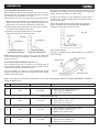
CUTTING CROWN MOLDING (FIG. EE, FF )
Your compound miter saw is suited for the difcult task of
cutting crown molding. To t properly, crown molding must be
compound-mitered with extreme accuracy.
The two surfaces on a piece of crown molding that t at
against the ceiling and wall are at angles that, when added
together equal exactly 90°.
In order to accurately cut crown molding for a 90° inside or
outside corner, lay the molding with its broad back surface
at on the saw table.
When setting the bevel and miter angles for compound
miters, remember that the settings are interdependent;
changing one changes the other, as well.
Fig. EE
Inside Corner
F
e
n
c
e
Bevel/Miter Settings
Settings for standard crown molding lying at on compound
miter saw table.
Outside Corner
OR
OL
IR
IL
Fig. FF
Miter Saw Table
Workpiece
Most crown molding has a top rear angle (the section that ts
at against the ceiling) of 52° and a bottom rear angle (the
section that ts at against the wall) of 38°.
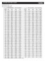
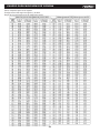
NOTE: The chart below references a compound cut for crown molding ONLY WHEN THE ANGLE BETWEEN THE WALLS
EQUALS EXACTLY 90°.
KEY
BEVEL SETTING MITER SETTING TYPE OF CUT
II 33.9º 31.6° Right
Inside corner-Left side
1. Position top of molding against fence.
2. Miter table set at RIGHT 31.6°.
3. LEFT side is nished piece.
ID 33.9º 31.6° Left
Inside corner-Right side
1. Position bottom of molding against fence.
2. Miter table set at LEFT 31.6°.
3. LEFT side is nished piece.
EI 33.9º 31.6° Left
Outside corner-Left side
1. Position bottom of molding against fence.
2. Miter table set at LEFT 31.6°.
3. RIGHT side is nished piece.
ED 33.9º 31.6° Right
Outside corner-Right side
1. Position top of molding against fence.
2. Miter table set at RIGHT 31.6°.
3. RIGHT side is nished piece.

CROWN MOLDING CHART
Compound miter saw
Miter and bevel angle settings
Wall to crewn molding angle
19
Page is loading ...
Page is loading ...
Page is loading ...
Page is loading ...
Page is loading ...
Page is loading ...
Page is loading ...
Page is loading ...
Page is loading ...
Page is loading ...
Page is loading ...
Page is loading ...
Page is loading ...
Page is loading ...
Page is loading ...
Page is loading ...
Page is loading ...
Page is loading ...
Page is loading ...
Page is loading ...
Page is loading ...
Page is loading ...
Page is loading ...
Page is loading ...
Page is loading ...
Page is loading ...
Page is loading ...
Page is loading ...
Page is loading ...
Page is loading ...
Page is loading ...
Page is loading ...
-
 1
1
-
 2
2
-
 3
3
-
 4
4
-
 5
5
-
 6
6
-
 7
7
-
 8
8
-
 9
9
-
 10
10
-
 11
11
-
 12
12
-
 13
13
-
 14
14
-
 15
15
-
 16
16
-
 17
17
-
 18
18
-
 19
19
-
 20
20
-
 21
21
-
 22
22
-
 23
23
-
 24
24
-
 25
25
-
 26
26
-
 27
27
-
 28
28
-
 29
29
-
 30
30
-
 31
31
-
 32
32
-
 33
33
-
 34
34
-
 35
35
-
 36
36
-
 37
37
-
 38
38
-
 39
39
-
 40
40
-
 41
41
-
 42
42
-
 43
43
-
 44
44
-
 45
45
-
 46
46
-
 47
47
-
 48
48
-
 49
49
-
 50
50
-
 51
51
-
 52
52


KNOVA KN M-2508RC Owner's manual
- Category
- Mitre saws
- Type
- Owner's manual
Ask a question and I''ll find the answer in the document
Finding information in a document is now easier with AI
in other languages
Related papers
Other documents
-
 Tradesman M3052LW Owner's manual
-
DeWalt DWS780 User manual
-
DeWalt DWS715-AR User manual
-
Craftsman Tech10 Electric User manual
-
-
-
-
-
-
