tropitone 401443FP Installation And Operating Instructions Manual
- Category
- Fireplaces
- Type
- Installation And Operating Instructions Manual

FIRE PIT
INSTALLATION
AND OPERATING INSTRUCTIONS
FOR MODELS 401100, 401154FP, 401158FP, 800154FP,
820649FP,
401442FP, 401443FP, 401467FP, 801486FP, 821486FP, BE42RFP,
BE42SFP, BE48RFP, BE48SFP, BE5442FP
INSTALLER: THIS MANUAL MUST BE LEFT WITH THE
APPLIANCE.
CONSUMER: KEEP THIS MANUAL FOR FUTURE
REFERENCE.
WARNING
Improper installation, adjustment, alteration, service, or maintenance can cause
severe injury or death and may result in property damage. Read these installation,
operating and maintenance instructions thoroughly before installing or servicing this
equipment.
WARN
I
NG
Do not store or use gasoline or other flammable vapors or liquids in or
near this or any other appliance.
An LP (Liquefied Petroleum) tank that is not connected for use shall not
be stored in or near this or any other appliance.
If you smell gas:
DANGER
Shut off gas to the appliance.
Extinguish any open flame.
If odor continues, keep away from appliance and immediately
call gas supplier and fire department.
WARN
I
NG
For Outdoor Use Only
!

R9T12FIRE
Page 2 of 16
Rev. F 10SEP14
INSTALLATION
Tropitone recommends that all gas
products be installed by professionals
that are licensed by the local authority
having jurisdiction in gas piping.
MAINTENANCE
Tropitone recommends that all gas products installed in the
USA and CANADA be serviced and maintained by
professionals that are certified by the National Fireplace
Institute (NFI) as NFI Gas Specialist or by the Wood
Energy Technical Training (WETT).
INSTALLER: THIS MANUAL MUST BE LEFT WITH THE
APPLIANCE.
CONSUMER: KEEP THIS MANUAL FOR FUTURE
REFERENCE.
Follow the instructions in this manual carefully to reduce the risk of personal injury, death
or property loss.
DANGER
CARBON MONOXIDE HAZARD
This appliance can produce carbon
monoxide which has no odor.
Using it in an enclosed space can cause
death.
Never use this appliance in an enclosed
space such as camper, tent, car, or
home.
Some information listed in this manual has headings which have been highlighted In order to assist
you in identify critical pieces of information. They can be identified as follows:
WARNING Contains information critical to the safe installation and operation of the unit.
DANGER Contains information critical to the safety of you, your personal property and others
around this product.
IMPORTANT Contains information that will help you to have the most enjoyable experience with
this unit and maintain serviceability.
WARNING It is the installer’s responsibility to ensure this product has been installed in
accordance with the local codes applicable and that the end user has been educated
on the safe and proper operation of the unit.
WARNING Tropitone recommends that all gas products installed in the USA and CANADA be
serviced and maintained by professionals that are certified by the National Fireplace
Institute (NFI) as NFI Gas Specialist or by the Wood Energy Technical Training
(WETT).

R9T12FIRE
Page 3 of 16
Rev. F 10SEP14
DANGER This product is not intended to be used as a starter for wood or any other
combustible material.
WARNING It is the installer’s responsibility to ensure this product has been installed in
accordance with all the local codes applicable. In the absence of local codes, please
follow:
For Fixed Piping Systems: The National Fuel Gas Code, ANSI
Z223.1/NFPA 54 or the International Fuel Gas Code.
For Electrical: The National Electrical Code, ANSI/NFPA 70.
WARNING Use only the gas or fuel type specified for this unit. See the label near the controls.
Verify the gas or fuel is correct and the proper pressure available. NEVER use an
alternative fuel, including bio-fuel, ethanol, or any other fuel type with this unit.
The proper pressure and gas type must be checked prior to installation. A 1/8” NPT
test port is provided at the burner assembly connection beneath the burner tray.
LP Gas:
Supply Pressure: Minimum 8.0” WC (water column), Maximum 15.0”” WC
Outlet Pressure : Minimum 10.0” WC, Maximum 12.0” WC
DANGER All Fire Pits are designed and intended for outdoor use only. Never install or operate
indoors. Burning gas (both Natural and LP) produces fumes which can be dangerous
if inhaled. Always insure there is proper ventilation when using any fire products.
DANGER All Fire Pits are designed and intended for outdoor use only. Never install or operate
indoors. Burning gas (both Natural and LP) produces very high temperatures.
Always insure all combustible materials are kept far enough away to prevent
accidental ignition.
IMPORTANT When selecting a location for this product, insure that there is at least 48” clearance
to access the controls and the gas tank on LP units. Any guard or other protective
device removed for servicing must be replaced prior to operating the appliance.
WARNING Never leave this product on when unattended. Educate all persons, including
children that may come in contact with this unit of the danger of high temperatures
produced when operating, including surface temperatures. Clothing and other
flammable materials should not be hung from the appliance, or placed on or near the
appliance. Young children should be carefully supervised when they are in the area
of the appliance.
IMPORTANT It is recommended that material such as granite, marble or other dense stone be
kept away from heat and flame due to the risk of cracking. Tropitone will not be held
responsible for materials damaged due to excessive heat.

R9T12FIRE
Page 4 of 16
Rev. F 10SEP14
DANGER Do not install this product under any type of covering, including overhangs, patio
covers, umbrellas, cabanas, tree limbs or branches. The risk of fire, inhalation of
fumes, and exposure to excessive heat increases greatly if this product is installed
under any type of covering, which could result in personal injury, damage to property
or death.
IMPORTANT
It is important that the gas line feeding the fire pit if piped is a minimum of
¾
”
or larger, based on the distance from the fuel source.
Choose a location which has proper drainage.
Choose a location with a minimum clearance of 48” from other structures.
WARNING It is the responsibility of the person installing this unit to test and verify that there are
no gas leaks after all connections are made. NEVER test for gas leaks with a flame.
Use only a gas leak detector or gas reactant.
WARNING Use only joint compound or tape that is approved for use with all types of gas. Apply
to all male pipe fittings only. DO NOT use on FLARED fittings. Be sure all joints are
tightened securely before lighting.
WARNING Installation and repair should be done by a qualified service person. The appliance
should be inspected before use and at least annually by a qualified service person.
More frequent cleaning may be required as necessary. It is imperative that control
compartment, burners, and circulating air passageways of the appliance be kept
clean.
DANGER When using glass media in a fire pit, use only approved fire glass and insure that
there is only enough to hide burner. Applying over ½” of any media over the burner
may create back pressure which can result in gas leakage from the air mixer. This
may result in a dangerous situation which can result in personal injury, damage to
property or death.
DANGER Do not use this appliance if any part has been under water. Immediately call a
qualified service technician to inspect the appliance and replace any part of the
control system and any gas control which has been under water.
Please read these instructions completely and make sure you understand them before proceeding.
Incorrect installation can result in a dangerous situation which can lead to property damage,
personal injury, or death

R9T12FIRE
Page 5 of 16
Rev. F 10SEP14
WARNING: The LP Gas
tank or cylinder used must comply
with the following requirements.
Use of other tanks or cylinders
which do not meet these
requirements may create an
unsafe condition which could
cause injury or death to you, or
damage to your personal property,
including the risk of fire or
explosion.
The cylinder or tank used must be:
1. Constructed and marked in accordance with the U. S. Department of Transportation
(D.O.T.) Specifications for LP-Gas Cylinders, or the Standard for Cylinders, Spheres and
Tubes for Transportation of Dangerous Goods and Commission, CAN/CSA-B339 as
applicable;
2. Provided with a Listed overfilling prevention device; and
3. Provided with a cylinder connection device compatible with the connection for the appliance.
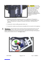
IMPORTANT: The LP Gas tank must be secured in the fire pit by placing the bottom ring in the
tank retaining ring (shown in blue), and securing with the tank retention bolt (shown in red) as
shown. It is important that the tank have a base with mounting holes which align with the gas tank
retaining bolts provided on this unit. See diagram above.

R9T12FIRE
Page 6 of 16
Rev. F 10SEP14
You can now connect your LP gas tank to the Fire Pit, using the standard propane gas hose with
built in regulator (shown in blue) shown. Hand tighten the propane tank gas connector (shown in
black), to the tank valve (shown in red). CAUTION: Do NOT use tools to tighten this connection
Open the gas valve on the tank by turning the gas valve knob (shown in green) counter-clockwise
(to the left) until fully open. See diagram located at bottom of page 5.
To remove the gas tank, first turn off the gas valve by turning the knob fully clockwise (right), then
unscrew the gas connector counter-clockwise (left) and move the gas hose to a secure location to
prevent accidental damage. Then loosen the front tank retention bolt to remove from tank retention
ring
WARNING: Inspect the hose and tank connector before each use to insure there is no damage
caused by rodents, weather or other conditions. NEVER use any Fire Pit which has any
components, including the gas hose or gas tank connector damaged in any way. If you find any
damage, turn off the valve on the gas tank and call a licensed repair technician to replace damaged
components. Replace any damaged items with components that have the exact same ratings.
WARNING: Before you turn on your Fire Pit for the first time, you must test your connections to
insure there are no leaks. Gas from leaking joints can pose a serious threat to your personal
property, yourself and others near this Fire Pit. NEVER use a lit match, lighter or other sources of
fire to check joints for leaks. Use a gas leak detection kit available from your local home
improvement store and follow all directions supplied by the manufacturer.
WARNING: Inspect the burner assembly at least every six (6) months to insure there is no
damage before use. Clean your burner, pilot and thermocouple at least every six months to insure
proper operation.
The spark used to ignite your Fire Pit
comes from a 9 volt battery located in the
Spark Igniter Power supply. The 9 volt
battery, which is installed in the Tropitone
Fire Pits, is shipped with a battery
terminal cover which must be removed
prior to the first use of the Fire Pit. To
remove the terminal cap (or replace the
battery), unscrew the round cap by
turning counter-clockwise (left) and
remove the battery. The battery terminal
cover is a small piece of plastic which is
easily removed. Once the terminal cover
has been removed, place the battery
back in the case and tighten the cap
completely by turning clockwise (right) to
insure a good connection.
RoundCapof9volt
batteryhousing

R9T12FIRE
Page 7 of 16
Rev. F 10SEP14
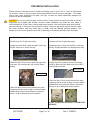
FIRE MEDIA INSTALLATION
Please follow the instructions below to add the finishing touch to your Fire Pit. Your Fire Pit needs a
fire media in order to get the proper flame characteristics from the burner assembly. The media
can be lava rocks, decorative fire glass, fire logs, or other fire media specifically designed for
outdoor fire pits and fireplaces.
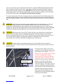
DANGER Do not block the pilot area or blow out box. Proper air flow is required in order to prevent
suffocation and possible gas buildup. Incorrect media installation will cause the pilot flame to
suffocate and turn off the fire pit or delay main burner ignition. If the main burner does ignite quickly,
gas can build up in the burner tray and ignite violently. Ignition of gas which has built up can create
an unsafe condition, and may cause injury or death, and may damage personal property. The
deeper your lava rock or glass the more risk of reducing or smothering the flame from the burner.
Lava Rock Only Application
1) Install your Fire Pit per instructions.
2) Apply lava rock ONLY deep enough to cover ring
and pan- less than 2” above fire ring.
3) Blow Out Box: Do not cover vents with lava rock-
leave open. Do not allow any rock to block flame
opening.
Decorative Glass Application
1) Install your Fire Pit per instructions.
2) Add base layer of lava rock as filler to hide pan
and ring. Height should be only slightly above ring.
3) Apply top coat of glass to lava rock just deep
enough to hide lava rock. Make sure you do NOT
cover the Blow Out Box.
Blow Out
Box
Blow Out
Box
4) Blow Out Box: Do not cover blowout box vents
or opening with lava rock or glass. Incorrect media
installation will cause the pilot flame to suffocate
and turn off pit or delay main burner ignition.
4) Blow Out Box: Do not cover blowout box vents
or opening with lava rock or glass. Incorrect media
installation will cause the pilot flame to suffocate
and turn off pit or delay main burner ignition.
DO NOT COVER VENTS! DO NOT COVER PILOT
OPENING!

R9T12FIRE
Page 8 of 16
Rev. F 10SEP14
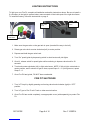
LIGHTING INSTRUCTIONS
To light your new Fire Pit, complete all installation and safety instructions above. Be sure to install a
9 volt battery in the ignition system battery case mounted on the inside post of the right door frame.
To install the battery, follow the instructions on page 6.
Gas
Valve
Knob
Spark Igniter
Switch
Gas Tank
Gas Valve
1. Make sure the gas valve on the gas tank is open (turned all the way to the left).
2. Rotate gas valve knob counter-clockwise (left) to center position.
3. Depress and hold the gas valve knob.
4. Turn “On” spark igniter by depressing switch in short bursts until pilot lights.
5. Once lit, release switch for spark igniter while continuing to depress valve knob for 20
seconds.
6. Turn knob counter-clockwise (left) to light main burner. NOTE: If fails to light, rotate knob to
center position, wait 5 minutes for gas to clear, repeat Steps 3 ~ 6. If pilot goes out, repeat
Steps 3 ~ 6.
7. Once Fire Pit has ignited, DO NOT leave unattended.
FIRE PIT SHUTDOWN
1. Turn “off” fire pit by slightly pressing and turning valve knob clockwise (right) to “OFF”
position.
2. Turn “off” gas to Fire Pit at LP tank or other remote location.
3. Once Fire Pit has cooled completely, use appropriate cover (sold separately) to protect Fire
Pit.

R9T12FIRE
Page 9 of 16
Rev. F 10SEP14
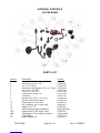
INTERNAL CONTROLS
(401100 BASE)
PARTS LIST
Item No.
1
Description
Gas Flex Line, 24” x 1/2"
Part No.
R15SP100
2
1/2” x 1/2” FIP 90
R15CO101
3
Gas Hose with Regulator, 3/8” x 12” Long
R18FH100
4
3/8” Flare x 3/8” MIPT
R18CO108
5
Elbow, 3/8” M x 3/8” F
R15CO100
6
Compression Fitting, 1/8”
R15CO104
7
Gas Valve
R18VL100
8
Ignition Wire, set of 3, 12” Long
R19WR100
9
Ignition Switch With Gasket
R19SW100
10
Knob, Black, for Gas Valve
R02MS102
11
Nut, Retaining, M1 for Gas Valve
R02NU501
12
Nipple, 3/8” x 1.5”
R15SP101
13
Gas Plumbing Support Weldment
W401100HGM
14A
Spark Igniter Power Supply (Cap)
R19NT101
14B
Spark Igniter Power Supply (Housing)
(Sold as Set)
15
9 Volt Battery
R15DC100
16
Brass Adapter, 3/8”
R15CO111

R9T12FIRE
Page 10 of 16
Rev. F 10SEP14
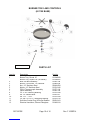
BURNER TRAY AND CONTROLS
(401100 BASE)
Pressure Test Port
PARTS LIST
Item No.
1
Description
Burner Tray, Round 18”
Part No.
R15MS300
Burner Tray, Square 18” (not shown)
R15MS301
2
Blow Out Box Assembly
R19NT108
3
Burner, 6 Point Arm, 12” Diameter
R18BA104
4
Nut, 1/2” Stainless Steel
R02NU500
5
Nipple, 1/2” Stainless Steel
R15CO106
6
Pilot & Thermocouple Assembly
R19TC100
7
Igniter Assembly
R19NT100
8
1/2" x 3/8” Reducing Bushing
R15CO108
9
3/8” LP Gas/Air Mixer
R18VL101
10
3/8” FPT – “TEE”
R15CO109
11
1/2" MPT x 1/8” FPT Reducing Bushing
R15CO110
12
13
Solid Hex Socket Plug W/Thread Sealant
Electrical Insulation, Silicone/Fiberglass
R02SC443
R19NS100

R9T12FIRE
Page 11 of 16
Rev. F 10SEP14
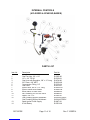
INTERNAL CONTROLS
(401400RD & 401400SQ BASES)
PARTS LIST
Item No.
1
Description
Gas Flex Line, 24” x 1/2"
Part No.
R15SP100
2
1/2” x 1/2” FIP 90
R15CO101
3
Gas Hose with Regulator, 3/8” x 12” Long
R18FH100
4
3/8” Flare x 3/8” MIPT
R18CO108
5
Compression Fitting, 1/8”
R15CO104
6
Gas Valve
R18VL100
7
Ignition Wire, set of 3, 12” Long
R19WR100
8
Ignition Switch With Gasket
R19SW100
9
Knob, Black, for Gas Valve
R02MS102
10
Nut, Retaining, M1 for Gas Valve
R02NU501
11
Nipple, 3/8” x 1.5”
R15SP101
12
Gas Plumbing Support Weldment
W401442FPSGV
Gas Plumbing Support Weldment
W401443FPSGV
13
Spark Igniter Power Supply
R19NT101
14
9 Volt Battery
R15DC100

R9T12FIRE
Page 12 of 16
Rev. F 10SEP14
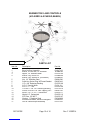
BURNER TRAY AND CONTROLS
(401400RD & 401400SQ BASES)
Pressure Test Port
PARTS LIST
Item No.
1
Description
Blow Out Box Assembly
Part No.
R19NT108
2
Burner, 6 Point Arm, 12” Diameter
R18BA104
3
Nipple, 1/2” Stainless Steel
R15CO106
4
Burner Tray, Round 18”
R15MS300
Burner Tray, Square 18” (not shown)
R15MS301
5
Nut, 1/2” Stainless Steel
R02NU500
6
Solid Hex Socket Plug W/Thread Sealant
R02SC443
7
1/2” x 3/8” Reducing Bushing
R15CO108
8
3/8” LP Gas/Air Mixer
R18VL101
9
3/8” FPT – “TEE”
R15CO109
10
1/2" MPT x 1/8” FPT Reducing Bushing
R15CO110
11
Screw, PHP #8 x 1/2” Self Tapping, SST
R02SC140
12
Elbow, 1/2” F x 1/2” F, Galvanized
R18CO117
13
Nipple,1/2”, Galvanized
R18CO116
14
3/8” Flare 1/2” MIPT
R18CO107
15
Washer, 1” Stainless Steel
R02WA880
16
Electrical Insulation, Silicone/Fiberglass
R19NS100
17
Pilot & Thermocouple Assembly
R19TC100

R9T12FIRE
Page 13 of 16
Rev. F 10SEP14
FIRE PIT NATURAL GAS CONVERSION AND OPERATING
INSTRUCTIONS
First turn the LP Gas tank (if installed) fully off by rotating the valve completely to the left until
closed. Then disconnect the LP Gas tank hose with built in regulator (shown in blue) by turning
the large connector (shown in black) fully counter-clockwise until the hose is completely
disconnected.
The proper pressure and gas type must be checked prior to installation. A 1/8” NPT test port is
provided at the burner assembly connection beneath the burner tray. When converting from LP
to Natural gas, installer must remove the supplied gas hose and LP regulator and install the
correct regulator for Natural gas. The regulator must limit the supply as specified below:
Natural Gas:
Supply Pressure:
Minimum 5.0” WC (water column), Maximum 10.0” WC
Operating Pressure:
Minimum 5.0” WC, Maximum 7.0” WC
Remove the LP Gas tank hose from the gas valve (shown in bronze) at the elbow (or straight
connector) coming out of the gas valve as shown above. Connect your inlet supply line,
including pressure regulator to this location. Follow all local codes. Do not install without a
regulator, which will limit your fuel supply to 5 inches of water column.

R9T12FIRE
Page 14 of 16
Rev. F 10SEP14
CAUTION: Use a joint compound or thread tape approved for the type of gas this appliance is
intended to use on all male threads EXCEPT compression threads. Never apply thread tape of
compound to compression threads.
Beneath the Burner tray, locate the Gas/Air Mixer in the plumbing. Remove the LP Gas/Air
Mixer and replace with the Natural Gas Orifice.
LP Gas/Air Natural
Mixer Gas Orifice


R9T12FIRE
Page 16 of 16
Rev. F 10SEP14
This Fire Pit has been tested and approved in accordance with ANSI Z21.97 by ICC-ES Listing
No. PMG-1114
Tropitone Furniture Co., Inc.
5 Marconi
Irvine, Ca 92618
949-951-2010
www.tropitone.com
1401 Commerce Blvd.
Sarasota, Fl 34243
© Tropitone Furniture Co., Inc, 2014
-
 1
1
-
 2
2
-
 3
3
-
 4
4
-
 5
5
-
 6
6
-
 7
7
-
 8
8
-
 9
9
-
 10
10
-
 11
11
-
 12
12
-
 13
13
-
 14
14
-
 15
15
-
 16
16


tropitone 401443FP Installation And Operating Instructions Manual
- Category
- Fireplaces
- Type
- Installation And Operating Instructions Manual
Ask a question and I''ll find the answer in the document
Finding information in a document is now easier with AI
Other documents
-
Endless Summer GAD15310ES Owner's manual
-
 THE OUTDOOR PLUS TOP-FSI Match Lit User manual
-
Endless Summer GAD17108ES User guide
-
Kingsman Fireplaces FP2085/2785 User manual
-
Elementi OFG121-NG User manual
-
Elementi OFG104-NG User manual
-
 Modeno OFG141LG-LP User manual
-
-
-

