16
Installation Instructions
4
ADJUST BURNER FLAMES
A
Turn all burners full on and check the flames.
They should be blue in color with some yellow
tipping at the ends of the flame. Foreign
particles in the gas line may cause an orange
flame at first, but this will soon disappear.
NOTE: For the 15,000 BTU/HR burner (on some
models) the cooktop burner knob should be
turned to the setting before the lowest setting.
This will ensure that the entire burner is
operating.
B
Turn the cooktop burner knob to the lowest
setting while observing the flame.
Adjust the low flame setting using the valve bypass
screw as follows:
Low-setting adjustments must be made with two
other burners in operation on a medium setting.
This prevents the low flame from being set too low,
resulting in the flame being extinguished when
other burners are turned on.
C
To adjust the flame, remove the knobs. Insert
a screwdriver through the access hole in valve
switch. Engage
adjustment screw in
valve. Refer to the
illustration below that
matches the adjustment
screw location for your
model.
• If the flames were too
small or fluttered, open
the valve more than
the original setting.
• If the flames blew
away from the burner,
close the valve more
than the original
setting.
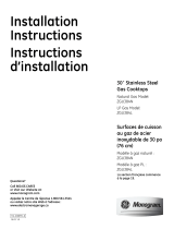
D
Make the adjustment by slowly turning the
screw until flame appearance is correct.
Note: Some models may contain a silicone shield which
covers the valve switch and access hole. A flashlight may
be required to locate the access hole. To access the valve
adjusting screw, push the screwdriver through this shield.
After adjustment, reseat the shield around the switch hub
with your fingers, after withdrawing the screwdriver.
E
Testing Flame Stability:
Test 1 – Turn the knob from “HI” to the lowest
setting quickly. If the flame goes out
at the lowest setting, increase the
flame size and test again.
Test 2 – With the burner on the lowest setting,
open and close the cabinet door
under the cooktop. If the flame is
extinguished by the air currents
created by the door movement,
increase the flame height and test
again.
F
Flame Recheck:
After the adjustment is made, turn all burners off.
Ignite each burner individually. Observe the flame
at the “HI” position. Rotate the valve to the lowest
setting and be sure that the flame size decreases
as the valve is rotated counterclockwise.
TO CONVERT THE COOKTOP BACK TO NATURAL
GAS, REVERSE THE STEPS UNDER MAKING THE
Propane (LP) CONVERSION.
Once the conversion is complete and checked ok,
fill out the Propane (LP) sticker and include your
name, organization and date conversion was
made. Apply the sticker near the cooktop gas
inlet opening to alert others in the future that this
appliance has been converted to Propane (LP) gas.
If converting back to natural gas from Propane
(LP), please remove the sticker so others know the
appliance is set to use natural gas.
MAKING THE Propane (LP) CONVERSION (CONT.)
15K burner
only
Reseat silicone shield
CORRECT INCORRECT