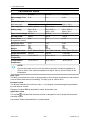
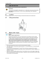
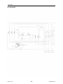
ESAB Origo™ Arc 250, 300, 400 is a welding power source for coated electrodes that gives direct current. It can weld various metals, including alloy and non-alloy steel, stainless steel, and cast iron. Arc 250 and Arc 300 can weld with coated electrodes from 1.6 to 5mm in diameter. Arc 400 can weld with electrodes up to 6mm in diameter.
ESAB Origo™ Arc 250, 300, 400 is a welding power source for coated electrodes that gives direct current. It can weld various metals, including alloy and non-alloy steel, stainless steel, and cast iron. Arc 250 and Arc 300 can weld with coated electrodes from 1.6 to 5mm in diameter. Arc 400 can weld with electrodes up to 6mm in diameter.


-
 1
1
-
 2
2
-
 3
3
-
 4
4
-
 5
5
-
 6
6
-
 7
7
-
 8
8
-
 9
9
-
 10
10
-
 11
11
-
 12
12
-
 13
13
-
 14
14
-
 15
15
-
 16
16
-
 17
17
-
 18
18
-
 19
19
-
 20
20
-
 21
21
-
 22
22
-
 23
23
-
 24
24


ESAB Origo™ Arc 250, 300, 400 is a welding power source for coated electrodes that gives direct current. It can weld various metals, including alloy and non-alloy steel, stainless steel, and cast iron. Arc 250 and Arc 300 can weld with coated electrodes from 1.6 to 5mm in diameter. Arc 400 can weld with electrodes up to 6mm in diameter.
Ask a question and I''ll find the answer in the document
Finding information in a document is now easier with AI
Related papers
-
ESAB Remote Outlet Kit Assembly Instruction
-
ESAB Warrior™ 400i cc/cv User manual
-
ESAB Arc 145 - Buddy™ Arc 145 User manual
-
ESAB ET 300i User manual
-
ESAB ES 300i User manual
-
-
-
-
-
ESAB Mig 6502c User manual