Page is loading ...

Table of Contents
Cover photo may show optional equipment
not supplied with standard unit.
Read the Operator’s Manual entirely. When you
see this symbol, the subsequent instructions and
warnings are serious - follow without exception.
Your life and the lives of others depend on it!
!
© Copyright 2017 Printed
30361A
RTA12 Series Rotary Tillers
311-785M
RTR12 & RTA12 Series (Serial No. 884764-)
RTR1242, RTR1250, RTR1258, RTR1266, & RTR1274
RTA1242, RTA1250, RTA1258, RTA1266, & RTA1274
Rotary Tillers
30345A
RTR12 Series Rotary Tillers
Operator’s Manual
9/06/17

Table of Contents
RTR12 & RTA12 Series (Serial No. 884764-) Rotary Tillers 311-785M
9/06/17
© Copyright 2017 All rights Reserved
Land Pride provides this publication “as is” without warranty of any kind, either expressed or implied. While every precaution has been taken in the
preparation of this manual, Land Pride assumes no responsibility for errors or omissions. Neither is any liability assumed for damages resulting from the use
of the information contained herein. Land Pride reserves the right to revise and improve its products as it sees fit. This publication describes the state of this
product at the time of its publication, and may not reflect the product in the future.
Land Pride is a registered trademark.
All other brands and product names are trademarks or registered trademarks of their respective holders.
Printed in the United States of America.
Important Safety Information . . . . . . . . . . . . . 1
Safety at All Times . . . . . . . . . . . . . . . . . . . . . . . . 1
Look For The Safety Alert Symbol . . . . . . . . . . . . . 1
Safety Labels . . . . . . . . . . . . . . . . . . . . . . . . . . . . . 4
Introduction . . . . . . . . . . . . . . . . . . . . . . . . . . . 8
Application . . . . . . . . . . . . . . . . . . . . . . . . . . . . . . . 8
Using This Manual . . . . . . . . . . . . . . . . . . . . . . . . . 8
Terminology . . . . . . . . . . . . . . . . . . . . . . . . . . . . . 8
Definitions . . . . . . . . . . . . . . . . . . . . . . . . . . . . . . 8
Owner Assistance . . . . . . . . . . . . . . . . . . . . . . . . . . 8
Serial Number . . . . . . . . . . . . . . . . . . . . . . . . . . . 8
Further Assistance . . . . . . . . . . . . . . . . . . . . . . . . 8
Section 1: Assembly and Set-Up . . . . . . . . . . 9
Dealer Preparations . . . . . . . . . . . . . . . . . . . . . . . . 9
Tractor Requirements . . . . . . . . . . . . . . . . . . . . . . . 9
Torque Requirements . . . . . . . . . . . . . . . . . . . . . . . 9
RTR & RTA Parking Stand Installation . . . . . . . . . . 9
RTR & RTA Rear Chain Installation . . . . . . . . . . . . 9
Reverse Rotation (RTR) Rotary Tillers . . . . . . . . . 10
RTR Front Deflector Assembly . . . . . . . . . . . . . 10
RTR 3-Point Hitch Assembly . . . . . . . . . . . . . . . 11
Standard Rotation (RTA) Rotary Tillers . . . . . . . . . 12
RTA 3-Point Hitch Assembly . . . . . . . . . . . . . . . 12
Tractor Hook-Up . . . . . . . . . . . . . . . . . . . . . . . . . . 13
Driveline Installation . . . . . . . . . . . . . . . . . . . . . . . 13
Check Driveline Collapsible Length . . . . . . . . . . 14
Shorten Driveline . . . . . . . . . . . . . . . . . . . . . . . . 15
Check Driveline Maximum Length . . . . . . . . . . . 15
Check Driveline Interference . . . . . . . . . . . . . . . 15
Section 2: Operating . . . . . . . . . . . . . . . . . . . .16
Operating Checklist . . . . . . . . . . . . . . . . . . . . . . . . 16
Inspections . . . . . . . . . . . . . . . . . . . . . . . . . . . . . . 16
Safety Information . . . . . . . . . . . . . . . . . . . . . . . . . 16
Transporting . . . . . . . . . . . . . . . . . . . . . . . . . . . . . 18
Parking . . . . . . . . . . . . . . . . . . . . . . . . . . . . . . . . . 18
General Operating Notes . . . . . . . . . . . . . . . . . . . 19
General Operating Instructions . . . . . . . . . . . . . . . 19
Section 3: Adjustments . . . . . . . . . . . . . . . . . 20
RTA & RTR12 Tiller Hitch Offset . . . . . . . . . . . . . . 20
Drive Chain Tension . . . . . . . . . . . . . . . . . . . . . . . 20
RTR12 Series Tillers . . . . . . . . . . . . . . . . . . . . . 20
RTA12 Series Tillers . . . . . . . . . . . . . . . . . . . . . 20
Rear Deflector . . . . . . . . . . . . . . . . . . . . . . . . . . . . 21
Skid Shoe Adjustment . . . . . . . . . . . . . . . . . . . . . . 21
Section 4: Maintenance and Lubrication . . . 22
Maintenance . . . . . . . . . . . . . . . . . . . . . . . . . . . . . 22
Tine Replacement . . . . . . . . . . . . . . . . . . . . . . . . . 22
Driveline Protection . . . . . . . . . . . . . . . . . . . . . . . . 22
Clutch Run-In . . . . . . . . . . . . . . . . . . . . . . . . . . . 22
Clutch Disassembly . . . . . . . . . . . . . . . . . . . . . . 23
Clutch Assembly . . . . . . . . . . . . . . . . . . . . . . . . 23
Storage . . . . . . . . . . . . . . . . . . . . . . . . . . . . . . . . . 24
Ordering Replacement Parts . . . . . . . . . . . . . . . . . 24
Lubrication Points . . . . . . . . . . . . . . . . . . . . . . . . . 25
Driveline U-Joint . . . . . . . . . . . . . . . . . . . . . . . . . 25
Driveline Shield Bearings . . . . . . . . . . . . . . . . . . 25
Driveline Shaft . . . . . . . . . . . . . . . . . . . . . . . . . . 25
Bearing On Right End Of Rotor Shaft . . . . . . . . . 26
Chaincase . . . . . . . . . . . . . . . . . . . . . . . . . . . . . 26
Gearbox . . . . . . . . . . . . . . . . . . . . . . . . . . . . . . . 26
Section 5: Troubleshooting . . . . . . . . . . . . . . 27
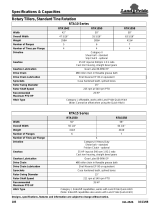
Section 6: Specifications & Capacities . . . . 28
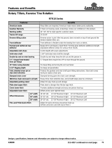
Section 7: Features & Benefits . . . . . . . . . . . 30
Section 8: Torque Values Chart . . . . . . . . . . 32
Section 9: Warranty . . . . . . . . . . . . . . . . . . . . 33
Table of Contents

1
9/06/17
RTR12 & RTA12 Series (Serial No. 884764-) Rotary Tillers 311-785M
Land Pride
Important Safety Information
Table of Contents
Important Safety Information
These are common practices that may or may not be applicable to the products described in
this manual.
!
Look For The Safety Alert Symbol
The SAFETY ALERT SYMBOL indicates there is a
potential hazard to personal safety involved and extra
safety precaution must be taken. When you see this
symbol, be alert and carefully read the message that
follows it. In addition to design and configuration of
equipment, hazard control, and accident prevention
are dependent upon the awareness, concern,
prudence, and proper training of personnel involved
in the operation, transport, maintenance, and storage
of equipment.
Be Aware of
Signal Words
A Signal word designates a degree or
level of hazard seriousness. The
signal words are:
Indicates an imminently hazardous
situation which, if not avoided, will
result in death or serious injury. This
signal word is limited to the most
extreme situations, typically for
machine components that, for
functional purposes, cannot be
guarded.
!
DANGER
Indicates a potentially hazardous
situation which, if not avoided, could
result in death or serious injury, and
includes hazards that are exposed
when guards are removed. It may also
be used to alert against unsafe
practices.
Indicates a potentially hazardous
situation which, if not avoided, may
result in minor or moderate injury. It
may also be used to alert against
unsafe practices.
!
WARNING
!
CAUTION
For Your Protection
Thoroughly read and understand
the “Safety Label” section, read all
instructions noted on them.
Shutdown and Storage
Lower machine to ground, put
tractor in park, turn off engine, and
remove the key.
Detach and store implements in an
area where children normally do
not play. Secure implement by
using blocks and supports.
OFF
R
E
M
O
V
E
Parts Manual QR Locator
The QR (Quick Reference) code on the front
cover and to the left will take you to the
Parts Manual for this equipment. Download
the appropriate App on your camera phone,
open the App, point your phone on the QR
code and take a picture.
Dealer QR Locator
The QR code on the left will
link you to available dealers
for Land Pride products.
Refer to Parts Manual
QR Locator on this page for
detailed instructions.
Safety at All Times
Thoroughly read and understand
the instructions given in this
manual before operation. Refer to
the “Safety Label” section, read all
instructions noted on them.
Do not allow anyone to operate
this equipment who has not fully
read and comprehended this
manual and who has not been
properly trained in the safe
operation of the equipment.
Operator should be familiar with all
functions of the unit.
Operate implement from the
driver’s seat only.
Make sure all guards and shields
are in place and secured before
operating implement.
Do not leave tractor or implement
unattended with engine running.
Dismounting from a moving tractor
could cause serious injury or
death.
Do not allow anyone to stand
between tractor and implement
while backing up to implement.
Keep hands, feet, and clothing
away from power-driven parts.
Wear snug fitting clothing to avoid
entanglement with moving parts.
Watch out for wires, trees, etc.,
when raising implement. Make
sure all persons are clear of
working area.
Turning tractor too tight may cause
implement to ride up on wheels.
This could result in injury or
equipment damage.
Do not carry passengers on
implement at any time.

2
RTR12 & RTA12 Series (Serial No. 884764-) Rotary Tillers 311-785M
9/06/17
Important Safety Information
Table of Contents
Transport
Machinery Safely
Comply with state and local laws.
Maximum transport speed for
implement is 20 mph. DO NOT
EXCEED. Never travel at a speed
which does not allow adequate
control of steering and stopping.
Some rough terrain require a
slower speed.
Sudden braking can cause a
towed load to swerve and upset.
Reduce speed if towed load is not
equipped with brakes.
Use the following maximum speed
- tow load weight ratios as a
guideline:
20 mph when weight is less
than or equal to the weight of
tractor.
10 mph when weight is more
than weight of tractor but less
than double the weight of
tractor.
IMPORTANT: Do not tow a load
that is more than double the
weight of tractor.
Use Safety
Lights and Devices
Slow moving tractors, self-
propelled equipment, and towed
implements can create a hazard
when driven on public roads. They
are difficult to see, especially at
night.
Flashing warning lights and turn
signals are recommended
whenever driving on public roads.
Practice Safe
Maintenance
Understand procedure before
doing work. Use proper tools and
equipment, refer to Operator’s
Manual for additional information.
Work in a clean dry area.
Lower the implement to the
ground, put tractor in park, turn off
engine, and remove key before
performing maintenance.
Allow implement to cool
completely.
Do not grease or oil implement
while it is in operation.
Inspect all parts. Make sure parts
are in good condition & installed
properly.
Remove buildup of grease, oil or
debris.
Remove all tools and unused
parts from implement before
operation.
These are common practices that may or may not be applicable to the products described in
this manual.
Operate Equipment Safely
The operator must not use drugs
or alcohol as they can change the
alertness or coordination of that
person while operating the
equipment. The operator should, if
he is taking over-the-counter
drugs, seek medical advice on
whether he can safely operate the
equipment.
Keep bystanders away.
Start tractor with gearshift in park
or neutral and park brakes set. Be
aware hydraulics are live upon
start-up and can move instantly.
Dig Safe, Call 811.
Always contact your local utility
companies (electrical, telephone,
gas, water, sewer, and others)
before digging so that they may
mark the location of any under
ground services in the area. Be
sure to ask how close you can
work to the marks they positioned.
Avoid contact with any over head
utility lines or electrically charged
conductors.

3
9/06/17
RTR12 & RTA12 Series (Serial No. 884764-) Rotary Tillers 311-785M
Land Pride
Important Safety Information
Table of Contents
Prepare for Emergencies
Be prepared if a fire starts.
Keep a first aid kit and fire
extinguisher handy.
Keep emergency numbers for
doctor, ambulance, hospital, and
fire department near phone.
911
Wear
Protective Equipment
Wear protective clothing and
equipment appropriate for the job.
Avoid loose fitting clothing.
Prolonged exposure to loud noise
can cause hearing impairment or
hearing loss. Wear suitable
hearing protection such as
earmuffs or earplugs.
Operating equipment safely
requires the full attention of the
operator. Avoid wearing radio
headphones while operating
machinery.
Avoid High
Pressure Fluids Hazard
Escaping fluid under pressure can
penetrate the skin causing serious
injury.
Avoid the hazard by relieving
pressure before disconnecting
hydraulic lines or performing work
on the system.
Make sure all hydraulic fluid
connections are tight and all
hydraulic hoses and lines are in
good condition before applying
pressure to the system.
Use a piece of paper or
cardboard, NOT BODY PARTS, to
check for suspected leaks.
Wear protective gloves and safety
glasses or goggles when working
with hydraulic systems.
DO NOT DELAY. If an accident
occurs, see a doctor familiar with
this type of injury immediately.
Any fluid injected into the skin or
eyes must be treated
within a few hours or
gangrene may
result.
These are common practices that may or may not be applicable to the products described in
this manual.
Handle
Chemicals Properly
Protective clothing should be
worn.
Handle all chemicals with care.
Follow instructions on container
label.
Agricultural chemicals can be
dangerous. Improper use can
seriously injure persons, animals,
plants, soil, and property.
Inhaling smoke from any type of
chemical fire is a serious health
hazard.
Store or dispose of unused
chemicals as specified by the
chemical manufacturer.
Tire Safety
Tire changing can be dangerous
and should be preformed by
trained personnel using the
correct tools and equipment.
When inflating tires, use a clip-on
chuck and extension hose long
enough to allow you to stand to
one side and NOT in front of or
over the tire assembly. Use a
safety cage if available.
When removing and installing
wheels, use wheel handling
equipment adequate for the
weight involved.
Keep Riders
Off Machinery
Riders obstruct the operator’s
view, they could be struck by
foreign objects or thrown from the
machine.
Never allow children to operate
equipment.

4
RTR12 & RTA12 Series (Serial No. 884764-) Rotary Tillers 311-785M
9/06/17
Important Safety Information
Table of Contents
Safety Labels
Your Rotary Tiller comes equipped with all safety labels in
place. They were designed to help you safely operate your
implement. Read and follow their directions.
1. Keep all safety labels clean and legible.
2. Refer to this section for proper label placement. Replace
all damaged or missing labels. Order new labels from your
nearest Land Pride dealer. To find your nearest dealer,
visit our dealer locator at www.landpride.com.
3. Some new equipment installed during repair requires
safety labels to be affixed to the replaced component as
818-130C
Operate only w/540 rpm PTO
RTR12 Series
30346A
30362A
RTA12 Series
specified by Land Pride. When ordering new components
make sure the correct safety labels are included in the
request.
4. Refer to this section for proper label placement.
To install new labels:
a. Clean the area the label is to be placed.
b. Spray soapy water on the surface where the label is to
be placed.
c. Peel backing from label. Press firmly onto the surface.
d. Squeeze out air bubbles with the edge of a credit card
or with a similar type straight edge.
KEEP FRONT DEFLECTOR IN PLACE
818-284C
RTR12 Series only
Thrown Object hazard
RTR12 Series
30346A

5
9/06/17
RTR12 & RTA12 Series (Serial No. 884764-) Rotary Tillers 311-785M
Land Pride
Important Safety Information
Table of Contents
818-171C
Rotating Tines Hazard!
RTR12 Series
30346A
30362A
RTA12 Series
RTA1258 Shown (Applicable for both RTA & RTR Series)
30362A
818-543C
RTR & RTA Series
Rotating Driveline Hazard - Keep Away!


8
RTR12 & RTA12 Series (Serial No. 884764-) Rotary Tillers 311-785M
9/06/17
Introduction
Table of Contents
Introduction
The parts on your Rotary Tiller have been specially
designed by Land Pride and should only be replaced with
genuine Land Pride parts. Contact a Land Pride dealer if
customer service or repair parts are required. Your Land
Pride dealer has trained personnel, repair parts, and
equipment needed to service the implement.
Serial Number
Model No. _____________Serial No. _____________
For quick reference and prompt service, record model
number and serial number in the spaces provided above
and again on warranty page 33. Always provide model
and serial number when ordering parts and in all
correspondences with your Land Pride dealer. Refer to
Figure 1 for location of your serial number plate.
Serial Number Plate Location
Figure 1
Further Assistance
Your dealer wants you to be satisfied with your Rotary
Tiller. If for any reason you do not understand any part of
this manual or are not satisfied with the service received,
the following actions are suggested:
1. Discuss the matter with your dealership service
manager making sure that person is aware of any
problems you may have and has had the opportunity
to assist you.
2. If you are still not satisfied, seek out the owner or
general manager of the dealership, explain the
problem, and request assistance.
3. For further assistance write to:
Land Pride
Service Department
P.O. Box 5060
Salina, Ks. 67402-5060
E-mail address
lpservicedept@landpride.com
RTA Series RTR Series
30364A
30357A
Land Pride welcomes you to the growing family of new
product owners.
This Rotary Tiller has been designed with care and built
by skilled workers using quality materials. Proper
assembly, maintenance, and safe operating practices will
help you get years of satisfactory use from this machine.
Application
The RTR12 and RTA12 Series Rotary Tillers are
designed and built by Land Pride to till soil for seedbed
and planting preparation with uses and applications in
landscaping, gardens, and residential areas. They are
adapted for 15-50 horsepower tractors with Category I
three-point hitch mounting, 540 rpm PTO speed and are
Quick-Hitch adaptable.
The reverse rotation tillers (RTR Series) tend to achieve
greater depth penetration resulting in moving and
pulverizing more soil. Also, they bury more of the residue
in the soil.
See “Specifications & Capacities” on page 28 and
“Features & Benefits” on page 30 for additional
information.
Using This Manual
•
This Operator’s Manual is designed to help familiarize
you with safety, assembly, operation, adjustments,
troubleshooting, and maintenance. Read this manual
and follow the recommendations to help ensure safe
and efficient operation.
• The information contained within this manual was
current at the time of printing. Some parts may change
slightly to assure you of the best performance.
• To order a new Operator’s or Parts Manual, contact
your authorized dealer. Manuals can also be
downloaded, free-of-charge, from our website at
www.landpride.com
Terminology
“Right” or “Left” as used in this manual is determined by
facing the direction the machine will operate while in use
unless otherwise stated.
Definitions
Owner Assistance
The Online Warranty Registration should be completed
by the dealer at the time of purchase. This information is
necessary to provide you with quality customer service.
IMPORTANT: A special point of information related
to the following topic. Land Pride’s intention is this
information must be read & noted before continuing.
NOTE: A special point of information that the
operator should be aware of before continuing.

9
9/06/17
RTR12 & RTA12 Series (Serial No. 884764-) Rotary Tillers 311-785M
Land Pride
Section 1: Assembly and Set-Up
Table of Contents
Support Leg & Rear Deflector Chain Assembly
Figure 1-1
RTR Series Shown
30728A
Section 1: Assembly and Set-Up
Torque Requirements
Check to make sure all nuts are tightened. Refer to
“Torque Values Chart” on page 32 to determine correct
torque values for common bolts. See “Additional Torque
Values” at bottom of chart for exceptions to standard
torque values.
RTR & RTA Parking Stand
Installation
Refer to Figure 1-1:
!
CAUTION
To avoid bodily injury caused by accidental falling of tiller,
stabilize unit with parking stand and support blocks.
1. Insert parking stand (#1) in support tube (#2).
2. Adjust parking stand to a height that will support the
tiller level while resting on skid shoes (#4).
3. Secure parking stand with wire retaining pin (#3).
Make sure wire retainer is hooked over the end of the
retaining pin.
RTR & RTA Rear Chain Installation
Refer to Figure 1-1:
1. Insert u-bolt (#5) into one end of rear chain (#6).
2. Install two nuts (#7) onto u-bolt an equal distance
from the threaded end.
3. Insert u-bolt through lock washers (#10), flat washers
(#8), and holes in deflector shield (#9) that are most
vertically located under slot (#13).
4. Secure u-bolt (#5) to deflector shield (#9) with flat
washers (#11) and 3/8
"-16 hex nuts (#12). Draw hex
nuts (#12) up snug and tighten hex nuts (#10) to the
correct torque.
5. Attach opposite end of rear chain (#6) to slot (#13).
Dealer Preparations
!
CAUTION
To avoid bodily injury caused by accidental falling of tiller,
securely support tiller on safe supporting stands or blocks.
This unit is shipped almost completely assembled.
Carefully follow instructions for final assembly.
Before attempting assembly check the following items.
Having all the needed parts and equipment readily at
hand will speed up your assembly task and will make the
job as safe as possible.
• Check for fasteners and pins that were shipped with
the tiller. Small hardware shipped loose from the
factory is contained in a bag. Larger parts are attached
to the shipping crate.
• Have ready for the assembly task a fork lift or loader
along with chains and safety stands sized for the job.
• Have a minimum of 2 people on hand during assembly.
Tractor Requirements
Tractor horsepower should be within the range noted
below. Tractors outside the horsepower range must not
be used.
Hitch Category . . . . . . . . . . . . . . . . . . . . 3-Point Cat. I
PTO Speed . . . . . . . . . . . . . . . . . . . . . . . . . 540 RPM
Horsepower Requirements:
42
" & 50" widths . . . . . . . . . . . . . . . . . . .15-35 HP
58
" & 66" widths . . . . . . . . . . . . . . . . . . . .20-40 HP
74
" Width. . . . . . . . . . . . . . . . . . . . . . . . . .25-50 HP
!
WARNING
Ballast weights may be required to maintain steering control.
Refer to your tractor Operator’s Manual to determine proper
ballast requirements.

10
RTR12 & RTA12 Series (Serial No. 884764-) Rotary Tillers 311-785M
9/06/17
Section 1: Assembly and Set-Up
Table of Contents
Reverse Rotation (RTR) Rotary
Tillers
The following are assembly instructions for reverse
rotation tillers (RTR12 Series). See page 12 for standard
rotation tillers (RTA12 Series).
IMPORTANT: Parking stand (#1) and wire retaining
pin (#7) must be installed at the correct height before
continuing. See “Parking Stand Installation” on page
9 for special instructions.
RTR Parking Stand and Front Deflector Assembly
Figure 1-2
30348A
RTR Front Deflector Assembly
Refer to Figure 1-2:
1. R e m o v e 3 / 8
"-16 x 1 1/2" bolts (#3), flat washers (#5),
lockwashers (#6), hex nuts (#4) and both front
deflector mounting bars (#2) from tiller frame.
2. Insert 3/8
"-16 x 1 1/2" GR5 hex head bolts (#3)
through flat washers (#5), upper mount bar (#2A),
front rubber deflector (#8) and mounting holes “A”.
3. Secure rubber deflector and upper mounting bar with
lower mount bar (#2B), lock washers (#6) and hex
nuts (#7).
4. Tighten hex nuts to the correct torque.

11
9/06/17
RTR12 & RTA12 Series (Serial No. 884764-) Rotary Tillers 311-785M
Land Pride
Section 1: Assembly and Set-Up
Table of Contents
RTR 3-Point Hitch Assembly
Refer to Figure 1-3:
1. Install upper right-hand hitch plate (#4) to gearbox
mounting frame with 5/8
"-11 x 1 3/4" GR5 cap
screw (#6), lockwashers (#14), and hex nuts (#9). Do
not tighten hardware at this time.
2. Repeat step 1 above to Install upper left-hand hitch
plate (#3) to gearbox mounting frame.
3. Install 1 1/4
" OD spacer (#1) between upper 3-Point
hitch plates (#4 & #5) with 3/4
"-10 x 4" GR5 cap
screw (#7), lockwasher (#15) and hex nut (#10).
4. Tighten all hex nuts (#9 & #10) to the correct torque.
5. Attach manual storage tube (#18) to hitch plate (#3)
with 1/4
"-20 x 1 1/4" GR5 cap screws (#8), flat
washers (#13) and nylock hex nuts (#12) as shown.
Tighten nuts to the correct torque.
6. Attach left-hand clevis (#5) to the square tube with
1/2
" u-bolt (#17) and 1/2" hex lock nuts (#11). Do Not
Tighten lock nuts.
7. Repeat step 6 above for the right-hand clevis.
Refer to Figure 1-4:
8. Position clevises 26 7/8
" apart from inside of clevis
plate to inside of clevis plate and centered off the
gearbox input shaft 13 7/16
" as shown.
Refer to Figure 1-3:
9. Tighten u-bolt locknuts (#11) to the correct torque.
10. Skip to “Tractor Hook-Up” instructions on page 13.
Clevis Location (RTR Series Shown)
Figure 1-4
30349A
26 7/8"
13 7/16"
RTR 3-Point Hitch & Driveline Assembly
Figure 1-3
30347A

12
RTR12 & RTA12 Series (Serial No. 884764-) Rotary Tillers 311-785M
9/06/17
Section 1: Assembly and Set-Up
Table of Contents
RTA Parking Stand, 3-Point Hitch & Driveline Assembly
Figure 1-5
30363A
Standard Rotation (RTA) Rotary
Tillers
The following are assembly instructions for standard
rotation tillers (RTA12 Series). See page 10 for reverse
rotation tillers (RTR12 Series).
RTA 3-Point Hitch Assembly
Refer to Figure 1-5:
1. Install upper right-hand hitch plate (#6) to gearbox
mounting frame with 5/8
"-11 x 1 3/4" GR5 cap
screws (#9), spring lockwashers (#17), and hex
nuts (#12). Do not tighten hardware at this time.
2. Repeat step 1 to Install upper left-hand hitch
plate (#5) to gearbox mounting frame.
IMPORTANT: Parking stand (#3) and wire retaining
pin (#20) must be installed at the correct height
before continuing. See “Parking Stand Installation”
on page 9 for special instructions.
3. Install 1 1/4" OD spacer (#1) between upper 3-Point
hitch plates (#5 & #6) with 3/4
"-10 x 4" GR5 cap
screw (#10), lockwasher (#18) and hex nut (#13).
4. Tighten all hex nuts (#12 & #13) to the correct torque.
5. Attach manual storage tube (#22) to hitch plate (#5)
with 1/4
"-20 x 1 1/4" GR5 cap screws (#11), flat
washers (#116) and nylock hex nuts (#15) as shown.
Tighten nuts to the correct torque.
6. Install driveline guard (#7) on backside of 3-Point
hitch plates with four 5/16
" wing screws (#8).
7. Attach left-hand clevis (#4) to the square tube with
1/2
" u-bolt (#21) and 1/2" hex lock nuts (#14). Make
certain clevis is oriented with hitch pin holes closest
to the top and the longer chamfer is on the bottom.
Do Not Tighten lock nuts.
8. Repeat step 7 above for the right-hand clevis.

13
9/06/17
RTR12 & RTA12 Series (Serial No. 884764-) Rotary Tillers 311-785M
Land Pride
Section 1: Assembly and Set-Up
Table of Contents
2. Secure tractor’s 3-Point lower hitch arms to the lower
hitch clevises using 7/8" diameter hitch pins. Secure
hitch pins with linch pins.
3. Secure tractor’s top center link to tiller hitch plates
using 3/4" diameter hitch pin (supplied by customer).
4. Place a level on the end plate and adjust tractor’s top
center link to level tiller from front to back.
5. Place level on the square tube and adjust one of the
two tractor’s lower 3-Point arms up or down to level
tiller from left to right.
6. Raise tiller up and remove parking stand from its
mounting tube. Turn parking stand upside down and
reinsert it several inches through the top of the
mounting tube. Secure parking stand using one of
the upper three holes with existing wire retaining pin.
7. Raise tiller fully up with 3-Point lift. Measure the
distance tines are off the ground. If distance exceeds
14
", adjust tractor’s 3-Point lift height limiter until
tines will not lift higher than 14 inches off the ground.
8. Continue with “Driveline Installation” on page 13.
Driveline Installation
The tiller driveline is coupled to the tractor shaft with
a push-pin coupler and to the implement shaft with a
bolted coupler. A slip clutch is provided on the implement
end for protection from shock loads.
Always engage PTO at low engine rpm to minimize
start-up torque. Drivelines with friction slip clutches
must go through a “run-in” operation prior to initial
use and after long periods of inactivity. See
“Driveline Protection” on page 22 for detailed
instructions on maintaining the slip clutch.
If the Rotary Tiller is used on more than one tractor, an
additional driveline may be required - especially if a quick
hitch is used.
IMPORTANT: To keep parking stand from becoming
damaged, always store stand in the transport
position before moving tractor with tiller attached.
Tractor Hook-Up
Figure 1-7
30360
Refer to Figure 1-6:
9. Position clevises 26 7/8
" apart from inside of clevis
plate to inside of clevis plate and centered off the
gearbox input shaft 13 7/16
" as shown.
Refer to Figure 1-5 on page 12:
10. Tighten u-bolt locknuts (#15) to the correct torque.
Clevis Location (RTA Series Shown)
Figure 1-6
Tractor Hook-Up
!
DANGER
A Crushing Hazard exists when hooking-up equipment to a
tractor. Do not allow anyone to stand between tractor and
implement while backing-up to implement. Do not operate
hydraulic 3-point lift controls while someone is directly
behind the tractor or near the implement.
!
WARNING
Lifting unit more than 14" above ground with PTO engaged or
engaging PTO with unit higher than 14" above ground can
break the driveline and could cause flying projectiles.
!
CAUTION
To avoid bodily injury caused by accidental falling of tiller,
stabilize unit with parking stand and support blocks.
Refer to Figure 1-7:
1. Back tractor up to tiller until lower 3-Point lift arms are
aligned with tiller hitch clevises.
30349A
26 7/8"
13 7/16"

14
RTR12 & RTA12 Series (Serial No. 884764-) Rotary Tillers 311-785M
9/06/17
Section 1: Assembly and Set-Up
Table of Contents
!
DANGER
Do not engage tractor PTO while hooking-up and unhooking
driveline or while someone is standing near the driveline. A
person’s body and/or clothing can become entangled in the
driveline resulting in serious injury or death.
!
WARNING
Do not use a PTO adaptor with a quick hitch. A PTO adapter
will increase strain on the tractor’s PTO shaft resulting in
possible damage to shaft and driveline.
!
DANGER
All guards and shields must be installed and in good working
condition at all times during tiller operation.
!
WARNING
Always disengage PTO, put gear selector in park or set park
brake, shut off tractor, remove ignition key, and wait for all
moving parts to come to a complete stop before dismounting
tractor.
!
WARNING
Do not over speed PTO or machine breakage may result. Some
tractors are equipped with multispeed PTO ranges. Be certain
your tractor’s PTO is set for 540 rpm.
1. Park tractor and tiller on a level surface. Raise tiller to
align gearbox input shaft level with tractor PTO shaft.
Securely block tiller at this height to keep unit from
lowering while attaching the driveline.
2. Place gear selector in park, shut tractor engine off,
set park brake and remove switch key.
Refer to Figure 1-3 on page 11 for RTA12 or
Figure 1-5 on page 12 for RTR12
3. Remove gearbox shaft protector (#24) from end of
gearbox shaft and attach slip clutch end of
driveline (#25) to gearbox input shaft.
IMPORTANT: The driveline must be lubricated
before putting it into service. Refer to “Lubrication
Points” on page 25 for detailed instructions.
IMPORTANT: Drivelines with friction clutches must
go through a “run-in” operation prior to initial use and
after long periods of inactivity.See “Driveline
Protection” on page 22 for detailed instructions.
IMPORTANT: If tiller is to be used on more than one
tractor, an additional driveline may be required,
especially if a quick hitch is used.
IMPORTANT: The tractor’s PTO shaft and tiller
gearbox shaft must be aligned and level with each
other during installation of driveline. This alignment
is the shortest distance between the two shafts.
4. Attach other end of driveline to tractor PTO shaft.
5. Move driveline yokes back and forth to ensure both
ends are secured to the shafts. Reattach any yoke
that is loose.
6. Attach safety chain on the outer driveline shield to the
tractor frame to restrict outer shield from rotating.
Re-latch safety chain to outer driveline shield.
7. Attach safety chain on the inner driveline shield to the
tiller frame to restrict inner shield from rotating. Re-
latch safety chain to inner driveline shield.
Check Driveline Collapsible Length
Refer to Figure 1-8:
1. Make sure driveline is installed properly before
checking driveline collapsed length (Refer to
“Driveline Installation” instructions on page 13).
2. With driveline level, measure 1" (“B” dimension)
back from universal joint shield to end of outer
driveline shield as shown in Figure 1-8.
a. If measurement is less than 1", shorten driveline.
a. If measurement is 1” or more, skip to “Check
Driveline Maximum Length” on page 15.
Driveline Shortening
Figure 1-8
NOTE: If driveline is too long to fit between tractor
and tiller, skip to “Shorten Driveline” on page 15.
IMPORTANT: Two safety chains are supplied with
the driveline. To keep driveline shields from rotating,
these chains must be attached to the outer and inner
driveline shields and to the tiller and tractor.
IMPORTANT: A driveline that is too long can bottom
out causing structural damage to tractor and tiller.
Always check driveline collapsed length during initial
setup, when connecting to a different tractor, and
when alternating between using a quick hitch and a
standard 3-point hitch. More than one driveline may
be required to fit all applications.
30563

15
9/06/17
RTR12 & RTA12 Series (Serial No. 884764-) Rotary Tillers 311-785M
Land Pride
Section 1: Assembly and Set-Up
Table of Contents
Shorten Driveline
Refer to Figure 1-8 on page 14:
Be sure to first check driveline collapsed length as
instructed above. If required, shorten driveline as follows:
1. Un-hook driveline from tractor PTO shaft and pull
outer and inner drivelines apart.
2. Reattach outer driveline to tractor PTO shaft. Pull on
inner and outer drivelines to be sure universal joints
are properly secured.
3. Hold inner and outer drivelines parallel to each other:
a. Measure 1" (“B” dimension) back from outer
driveline universal joint shield and make a mark at
this location on the inner driveline shield.
b. Measure 1" (“B” dimension) back from the inner
driveline universal joint shield and make a mark at
this location on the outer driveline shield.
4. Remove driveline and safety chains from tractor and
gearbox.
5. Measure from end of inner shield to scribed mark
(“X” dimension). Cut off inner shield at the mark. Cut
same amount off the inner shaft (“X1” dimension).
6. Measure from end of outer shield to scribed mark
(“Y” dimension). Cut off outer shield at the mark. Cut
same amount off the outer shaft (“Y1” dimension).
7. Remove all burrs and cuttings.
8. Continue with “Check Driveline Maximum Length”.
Check Driveline Maximum Length
Refer to Figure 1-9:
The driveline maximum allowable length must, when fully
extended, have a minimum overlap of the profile tubes by
not less than 1/3 the free length with both inner and outer
profile tubes being of equal length.
1. If not already completed, apply multi-purpose grease
to inside of outer profile and reassemble driveline.
2. Assemble the two driveline profiles together with just
1/3 overlapping of the profile tubes as shown below.
Once assembled, measure and record the maximum
allowable length for future reference.
Record Maximum Allowable Length here: ________
Figure 1-9
24513
Outer Shielding has been removed for clarity.
3. Reattach driveline to tractor and gearbox shaft
following “Driveline Installation” steps 1 to 7 on
page 14.
4. Continue with “Check Driveline Interference”.
Check Driveline Interference
1. Start tractor and raise Rotary Tiller just enough to
remove support blocks from under tiller.
2. Slowly engage tractor hydraulic 3-Point control lever
to lower tiller while checking for sufficient drawbar
clearance. Move drawbar ahead, aside or remove if
required.
Refer to Figure 1-10:
!
WARNING
Lifting unit more than 14" above ground with PTO engaged or
engaging PTO with unit higher than 14" above ground can
break the driveline and could cause flying projectiles.
!
WARNING
The driveline must not exceed an angle of 25 degrees up or
down while operating. Exceeding this angle with driveline
rotating can break the driveline and cause flying projectiles.
3. With PTO off, raise implement fully up and make the
following checks below. If driveline exceeds any of
the limits listed, set tractor 3-Point lift limiter at a
height that will keep the driveline within its lift limits to
avoid premature driveline breakdown.
• Tines do not exceed more than 14" off the ground.
• Driveline does not exceed 25
o
up.
• Driveline does not exceed maximum allowable
length recorded in step 2 under “Check Driveline
Maximum Length” on this page.
Maximum PTO Driveline Movement During Operation
Figure 1-10
24872

16
RTR12 & RTA12 Series (Serial No. 884764-) Rotary Tillers 311-785M
9/06/17
Section 2: Operating
Table of Contents
Operating Checklist
Hazard control and accident prevention are dependent
upon the awareness, concern, prudence, and proper
training involved in the operation, transport,
maintenance, and storage of the Rotary Tiller. Therefore,
it is absolutely essential that no one operates the Rotary
Tiller without first having read, fully understood, and
become totally familiar with the Operator’s Manual. Make
sure the operator has paid particular attention to:
• Important Safety Information, pages 1 to 7
• Section 1: Assembly and Set-Up, page 9
• Section 2: Operating, page 16
• Section 3: Adjustments, page 20
• Section 4: Maintenance and Lubrication, page 22
Inspections
Make the following inspections with tiller attached to a
tractor, PTO disengaged and completely stopped.
Operating Checklist
4Check
Page No.
Inspect tractor safety equipment to make sure it is in
good working condition.
See Tractor
Manual
Check all guards and shields to make certain they are in good working
condition, in place and secured.
Carefully raise and lower implement to ensure drawbar, tires, and
other tractor parts do not contact tiller frame or PTO driveline.
Check driveline to be sure it is securely connected to
tractor PTO shaft and tiller gearbox shaft.
Refer to “Driveline Installation”.
Page 13
Check drive chain tension.
Refer to “Drive Chain Tension”.
Page 20
Check tiller depth setting.
Refer to “Skid Shoe Adjustment”.
Page 21
Check driveline slip clutch to make sure disks will slip.
Refer to “Driveline Protection”
Page 22
Check for worn, bent, broken, loose and/or missing
tines. Replace tines as needed.
Refer to “Tine Replacement”
Page 22
Grease driveline shaft and all other grease fittings
Refer to “Lubrication Points”.
Page 25
Check oil level in gearbox. Make sure all plugs
have been replaced when completed.
Refer to “Gearbox Lubrication”.
Page 26
Check oil level in chaincase. Make sure all plugs have
been replaced when completed.
Refer to “Chaincase Lubrication”.
Page 26
Check tiller initially and periodically for loose bolts and
pins. Refer to “Torque Values Chart for Common Bolt
Sizes” for torque values.
Page 32
Safety Information
!
DANGER
Do not engage tractor PTO while hooking-up and unhooking
driveline or while someone is standing near the driveline. A
person’s body and/or clothing can become entangled in the
driveline resulting in serious injury or death.
!
DANGER
Keep yourself and all others away from rotating tines and
drive train. Always disengage PTO and lockout power source
before making adjustments or servicing the tiller. A person’s
body, hair, or clothing can become entangled in rotating
components causing serious bodily injury or death.
!
DANGER
Keep away from the rotating hex drive shaft between the
gearbox and chaincase. A person can become entangled in the
shaft causing serious bodily injury or death.
!
DANGER
Make all 3-point hydraulic adjustments from the tractor seat.
Never make hydraulic adjustments while standing alongside
the tractor or behind the tractor.
!
DANGER
PTO shaft shield, gearbox shields, driveline shields, and
driveline safety chains must be installed and in good working
condition while operating tiller to avoid injury or death from
entanglement in a rotating driveline.
!
DANGER
Do not operate a broken or bent driveline. Such drivelines can
break apart while rotating at high speeds causing serious
injury or death. Always remove Rotary Tiller from service
until damaged drivelines are repaired or replaced.
!
DANGER
Clear area of debris before tilling. Mark any potential hazards
that cannot be removed such as tree stumps, post, rocks, holes,
and drop-offs with a visible flag.
!
DANGER
Keep front rubber dirt deflector on the RTR tiller in place
while operating the unit. Objects can be thrown forward
toward the operator causing serious bodily injury or death.
!
DANGER
Do not point outlet toward people, animals, or buildings and
keep people and animals away from outlet during operation.
Tine impact on objects can cause projectiles resulting in
bodily injury or death.
Section 2: Operating

17
9/06/17
RTR12 & RTA12 Series (Serial No. 884764-) Rotary Tillers 311-785M
Land Pride
Section 2: Operating
Table of Contents
!
DANGER
Do not till across steep inclines exceeding 15 degrees. The
action of the tines being forced down into the ground can
cause the tractor to roll-over resulting in serious injury or
death. Consult your tractor’s manual for acceptable inclines
the tractor is capable of traveling across.
!
DANGER
Always disengage PTO before lifting tiller up and never
operate tiller in the raised position. The tiller can discharge
objects at high speeds resulting in injury or death.
!
DANGER
Do not use tiller as a working platform. The tiller is not
properly designed or guarded for this use. Using tiller as a
working platform can cause serious injury or death.
!
WARNING
Never allow children or other riders on the tractor or tiller.
They can fall and be ran over causing serious injury or death.
!
WARNING
Do not use a PTO adaptor with a quick hitch. A PTO adapter
will increase strain on the tractor’s PTO shaft resulting in
possible damage to shaft and driveline.
!
WARNING
Use Rotary Tiller for its intended purpose only. Do not use
tiller to lift or carry objects; to pull fence posts, stumps, or
other objects; or to tow other equipment. Doing so can
damage the tiller, cause serious bodily injury, or death.
!
WARNING
Always disengage PTO, put gear selector in park or set park
brake, shut off tractor, remove ignition key, and wait for all
moving parts to come to a complete stop before dismounting
tractor.
!
WARNING
Always make certain driveline yokes are secured to the tractor
PTO shaft and gearbox input shaft before engaging PTO. A
loose driveline can slip off the end of a connected shaft while
rotating and cause serious bodily injury or death.
!
WARNING
Do not allow anyone to operate this Rotary Tiller who has not
been properly trained in its safe operation or anyone who is
under the age of 16.
!
WARNING
Do not operate tiller with loose pins, bolts and nuts. Loose
hardware can result in a serious breakdown causing bodily
injury or death.
!
WARNING
Do not over speed PTO or machine breakage may result. Some
tractors are equipped with multispeed PTO ranges. Be certain
your tractor’s PTO is set for the tiller’s rated PTO speed. See
Specifications & Capacities for rated PTO speed.
!
CAUTION
Make certain you are not working over any underground
wiring, pipes, or other obstructions. If there is doubt, contact
your local utility services so that they may mark the location
of all underground utilities in the area. Be sure to ask how
close you can work to the marks or flags they positioned.
IMPORTANT: Make sure all safety labels are in their
proper location and in good condition before
operation. Follow all directions on the safety labels.
IMPORTANT: Do not alter tiller in a way which will
adversely affect its performance or reliability or use
the tiller for a purpose for which it was not designed.
NOTE: To protect the parking stand from becoming
bent while transporting and tilling the soil, always
store it upside down in its mount.

18
RTR12 & RTA12 Series (Serial No. 884764-) Rotary Tillers 311-785M
9/06/17
Section 2: Operating
Table of Contents
Transporting
Refer to Figure 2-1:
!
CAUTION
When traveling on public roads whether at night or during the
day, use accessory lights and devices for adequate warning to
operators of other vehicles. Comply with all federal, state, and
local laws.
1. When raising tiller to transport position, be sure the
driveline does not contact tractor or tiller. Adjust
tractor’s 3-Point hitch lift height so that the tiller tines
are not lifted more than 14 inches off the ground to
prevent driveline damage.
Refer to Figure 2-1:
2. Remove parking stand (#4) from support tube, turn
stand upsidedown and replace through top of
support tube as shown. Secure stand with wire
retaining pin (#5).
Parking Stand in Transport Position
Figure 2-1
3. Be sure to reduce tractor ground speed when turning,
and leave enough clearance so tiller does not
contact obstacles such as buildings, trees or fences.
4. Select a safe ground travel speed when transporting
from one area to another. When traveling on
roadways, transport in such a way that faster moving
vehicles may pass you safely.
5. When traveling over rough or hilly terrain, shift tractor
to a lower gear.
IMPORTANT: Always disengage PTO before raising
tiller to transport position.
30350A
Parking
The following steps should be taken when preparing to store
the tiller or unhitch it from the tractor.
Refer to Figure 2-2:
1. Adjust right-hand skid shoes (#1) down before
unhitching tiller from the tractor:
a. Loosening pivot bolt (#2A) at the shoe’s front.
b. Remove adjusting bolt (#2B) at the shoe’s rear.
c. Pivot skid shoe down and replace pivot bolt (#2B)
and lock washer (#3) in the second hole down
from the top as shown.
d. Tighten bolts (#2A & #2B) to the correct torque.
2. Repeat step 1 to adjust the left-hand skid shoe down.
3. Remove parking stand (#5) from support tube, turn
stand upright and replace it through bottom of
support tube.
4. Set parking stand (#5) to desired height for re-hook-
up and install wire retaining pin (#4) to lock in place.
5. Park tiller on a level, solid area. Shut tractor engine
off and engage parking brake.
6. Unhitch tiller from tractor.
!
WARNING
Place support blocks under tiller as needed to prevent unit
from tipping over onto a child and/or an adult. A tiller that tips
over can result in injury or death.
7. After unhooking tiller, check tiller for stability by
physically applying pressure at the hitch plates to see
if it will tip forward or backwards. If the tiller moves in
either direction, then block under the tiller as needed
to prevent that movement.
8. See “Storage” on page 24 for additional information
on long term storage of your tiller.
Parking Stand & Skid Shoe in Parking Position
Figure 2-2
IMPORTANT: It is important to adjust skid shoes
down to stabilize the tiller when parked.
30351A
/