Page is loading ...

EchoPro
®
Intrinsically Safe Radar Level Transmitter
Flowline, Inc. | 10500 Humbolt Street, Los Alamitos, CA 90720 p 562.598.3015 f 562.431.8507 w flowline.com MN301900 Rev B
LR11, LR16, LR21, LR26 & LR31 Series Manual

| 2 MN301900 Rev B
Introduction / Table of Contents Step One
TABLE OF CONTENTS Page
Section One | Introduction: .............................................................................................................................. 2
Table of Contents: ................................................................................................................................... 2
Sensor Models: ....................................................................................................................................... 5
Operating Principle: ................................................................................................................................. 6
Features: ................................................................................................................................................. 6
Benefits: .................................................................................................................................................. 6
Limitations: .............................................................................................................................................. 6
Specifications: ......................................................................................................................................... 7
Intrinsically Safe Control Drawings: ........................................................................................................ 12
Labels for Intrinsic Safety: ...................................................................................................................... 13
Dimensions: ........................................................................................................................................... 14
Safety Precautions: ............................................................................................................................... 17
Section Two | Getting Started: ....................................................................................................................... 18
Setup Overview: .................................................................................................................................... 18
Part Number: ......................................................................................................................................... 20
Section Three | Install Sensor: ....................................................................................................................... 22
Installation Requirements: ..................................................................................................................... 22
FCC Conformity: ..................................................................................................................................... 23
LR16 Antenna Preparation: ................................................................................................................... 24
Mounting Position: ................................................................................................................................. 25
Flange Riser Installation: ....................................................................................................................... 28
Beam Angle: .......................................................................................................................................... 29
Stand Pipe Installation: .......................................................................................................................... 30
Bypass Installation: ............................................................................................................................... 31
LR31 Sensor Installation: ...................................................................................................................... 32
LR98 Display Installation: ...................................................................................................................... 33
Section Four | Wire Sensor: ........................................................................................................................... 34
Terminal Wiring: .................................................................................................................................... 34
HART
®
Wiring: ........................................................................................................................................ 35
HART
®
Device descriptors (DD files): .................................................................................................... 35
Standard vs Multidrop: ........................................................................................................................... 35
LR31 configuration: ................................................................................................................................ 36
LR31 Wiring and Description: ................................................................................................................. 36
USING LR98 DISPLAY AS HMI FOR LR31 SERIES: ............................................................................ 37
Wiring to Displays, Controllers & PLCs: ................................................................................................ 38

MN301900 Rev B 3 |
Introduction / Table of Contents (continued) Step One
Section Five | Configuration Using Display: ................................................................................................. 40
Basic Configuration Overview: .............................................................................................................. 40
Basic HART communicator overview: .................................................................................................... 41
Units of Measurement: ................................................................................................................ 42
Sensor Height: ............................................................................................................................ 42
Fill-Height:................................................................................................................................... 43
Maximum Range:........................................................................................................................ 43
Dead Band: ................................................................................................................................. 44
Echo Curve: ................................................................................................................................ 44
Using the Display: ................................................................................................................................. 45
Changing Display Values: ..................................................................................................................... 46
Step 1 - Measure the Tank: ................................................................................................................... 47
Step 2 - Set the Units of Measurement: ................................................................................................ 48
Step 3 - Set the Sensor Height (4mA): .................................................................................................. 49
Step 4 - Set the Fill-Height (20mA): ....................................................................................................... 50
Step 5 - Set the Range (Maximum Range): .......................................................................................... 51
Step 6 - Set the Dead Band: ................................................................................................................. 52
Step 7 - Check the Echo Curve: ............................................................................................................ 53
Section Six | Process Adjustments: .............................................................................................................. 54
Process Adjustments Overview: ............................................................................................................ 54
Fast Filling or Emptying of Liquid: .............................................................................................. 55
Liquid Requiring First Echo Adjustment: ..................................................................................... 56
Liquid Surface is Turbulent or Agitated: ..................................................................................... 57
Foam on the Surface of the Liquid: ............................................................................................ 58
Liquids with Low Dielectric: ......................................................................................................... 59
Sensor Installed in a Stand Pipe or Sight Glass: ....................................................................... 60
Section Seven | Advanced Adjustments: ...................................................................................................... 61
Advanced Adjustments Overview: ......................................................................................................... 61
4-20mA Reverse Output: ....................................................................................................................... 62
Fail-Safe Output: ................................................................................................................................... 63
Minimum Current Output: ...................................................................................................................... 64
HART
®
Operation Mode: ....................................................................................................................... 65
Create a New False Echo Curve: .......................................................................................................... 66
Update an Existing False Echo Curve: .................................................................................................. 67
Section Eight | Troubleshooting: .................................................................................................................... 68
Troubleshooting Overview: .................................................................................................................... 68
Measurement Status: ............................................................................................................................ 69
Peak Values: ......................................................................................................................................... 70
Simulation: ............................................................................................................................................. 71
First Echo Adjustment: .......................................................................................................................... 72
Echo Curve Zoom: ................................................................................................................................ 73
False Echo Curve Delete: ..................................................................................................................... 74
Reset: .................................................................................................................................................... 75

| 4 MN301900 Rev B
Introduction / Table of Contents (continued) Step One
Section Nine | Appendix: ................................................................................................................................. 76
Configuration Menu: .............................................................................................................................. 76
Empty Configuration: ............................................................................................................................. 77
Full Configuration: ................................................................................................................................. 77
Medium: ................................................................................................................................................. 78
Liquid Medium: ........................................................................................................................... 78
Solids Medium: ........................................................................................................................... 79
Low Dielectric Medium: .............................................................................................................. 80
Dampen: ................................................................................................................................................ 80
Scaled Units: ......................................................................................................................................... 81
Range: ................................................................................................................................................... 81
Dead Band: ........................................................................................................................................... 81
Display Menu: ........................................................................................................................................ 82
Display Value: ....................................................................................................................................... 82
LCD Contrast: ........................................................................................................................................ 82
Diagnostics Menu: ................................................................................................................................. 83
Peak Values: ......................................................................................................................................... 83
Measurement Status: ............................................................................................................................ 83
Echo Curve: ........................................................................................................................................... 84
Simulation: ............................................................................................................................................. 84
Service Menu: ....................................................................................................................................... 85
False Echo: ........................................................................................................................................... 86
Output Settings: ..................................................................................................................................... 86
Reset: .................................................................................................................................................... 87
Units of Measurement: .......................................................................................................................... 87
Language: ............................................................................................................................................. 87
HART
®
Operational Mode: ..................................................................................................................... 87
Information: ........................................................................................................................................... 88
Factory Settings: ................................................................................................................................... 89
User Configuration: ............................................................................................................................... 89
Troubleshooting: ..................................................................................................................................... 90
Section Ten | Warranty, Returns and Limitations: ........................................................................................ 92
Warranty: ............................................................................................................................................... 92
Returns: .................................................................................................................................................. 92
Limitations: ............................................................................................................................................. 92

MN301900 Rev B 5 |
Introduction / Table of Contents (continued) Step One
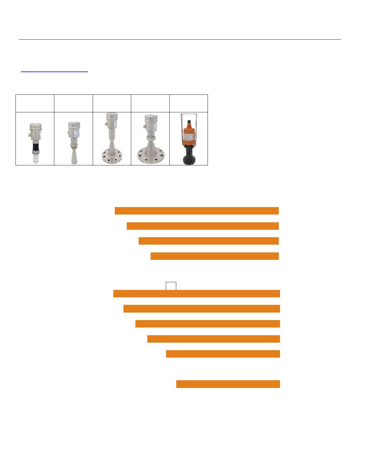
SENSOR MODELS
Offered in eight different models, EchoPro
®
is an intrinsically safe, two-wire, pulse radar level sensor that
provides a continuous 4-20 mA current output that’s proportional to the liquid level in a tank or sump. Make
sure that the model purchased is appropriate for your application.
Series
Max.
Range
Beam Angle Material Mounting
FCC
Compliance
Application
LR11
32.81’
(10m)
22° PFA 1-1/2” NPT
Part 15.209,
Class A
Corrosive liquids under
simple process
conditions
LR16
98.42’
(30m)
18° (2” horn)
316L SS 1-1/2” NPT
Part 15.209,
Class A
Storage tanks & process
tanks under difficult
process conditions
12° (3” horn)
Part 15.256,
Class B
8° (4” horn)
Part 15.256,
Class B
LR21
65.61’
(20m)
12°
(3” Flange)
316L SS
with PTFE
cover
3” ANSI
flange
Part 15.256,
Class B
Aggressive liquids under
extremely difficult
process conditions
8°
(4” flange)
4” ANSI
flange
LR26
114.83’
(35m)
20°
316L SS
with PTFE
cover
4” ANSI
flange
6” ANSI
flange
Part 15.209,
Class A
Storage tank & process
tanks under extremely
difficult process
conditions
LR31
98.42’
(30m)
12° PA66
Bracket or
top mounted
(1”) conduit
Part 15.256,
Class B
Water processing, lift
stations, storm water and
sump process conditions

| 6 MN301900 Rev B
Introduction / Table of Contents (continued) Step One
OPERATING PRINCIPLE
The sensor emits a microwave pulse from its antenna, which travels at the speed of light to the surface of the
medium below. A portion of that energy reflects off the medium and returns to the antenna. The time gap
between energy emission and receipt is called the “time of flight”, and is proportional to the distance between
the medium surface and the sensors measurement location, as at the bottom of the antenna. The sensor
measures the time of flight and translates this value into a continuous 4-20mA signal output that’s proportionate
to level within a defined measurement span.
FEATURES
Easy configuration with LCD push button display module
Adjustable loop fail-safe, no change, 20.5 mA, 22 mA
Small 12” (30.48cm) dead band enables full tank measurement
Recognition, storage and deletion of false echo signal returns
BENEFITS
Unaffected by physical process and environmental conditions
Ideal for applications with higher temp, pressure, foam, vapor and vacuum
Strong signal penetrability with minimal attenuation over distance
LIMITATIONS (FACTORS THAT COULD INFLUENCE PERFORMANCE)
Air particulates with a high dielectric constant value such as lead or ferroalloy
Highly dense air particulates that attenuate microwave emission and receipt
Material build-up on the antenna that degrades microwave emission and receipt
Mediums that have an extremely low dielectric constant value with little reflectivity

MN301900 Rev B 7 |
Introduction / Table of Contents (continued) Step One
SPECIFICATIONS
Measurement Range: LR11: .. 32.81 feet (10m) LR16: 98.42 feet (30m)
(maximum) LR21: 65.51 feet (20m) LR26: 114.83 feet (35m)
LR31: .. 98.42 feet (30m)
Dead Band: 12” (30.48cm) / Factory Set -
Note: Can be lowered to 2” from the bottom of the antenna
Measurement Accuracy: LR11: .. ±5 mm LR16: ±3mm
(see charts on pages 8 & 9) LR21: ±3mm LR26: ±10mm
LR31: ±3mm
Display Resolution: 1 mm
Frequency Range: 26 GHz: LR11, LR16, LR21 & LR31 series
6.3 GHz: LR26 series only
Measurement Interval: About 1 sec (dependent on configuration settings)
Adjustment Time: About 1 sec (dependent on configuration settings)
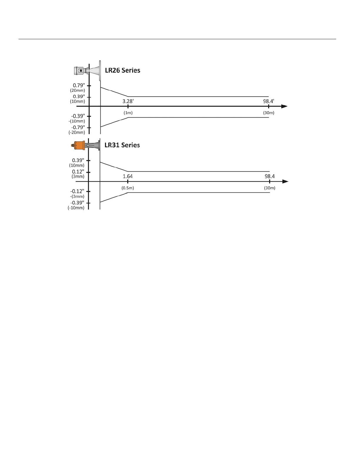
Beam Angle: LR11: 22° LR21: 12° - 3” ANSI Flange
LR16: 18° - 2” (48mm) Horn 8° - 4” ANSI Flange
12° - 3” (78mm) Horn LR26: 20°
8° - 4” (98mm) Horn LR31: 12°
Process Connection: LR11: 1-½” NPT LR26: 4” ANSI Flange
LR16: 1-½” NPT 6” ANSI Flange
LR21: 3” ANSI Flange LR31: Bracket or top
4” ANSI Flange mount (1”) NPT
Material:
Series LR11 LR16 LR21 LR26 LR31
Flange
N/A 316L SS N/A
Enclosure
316L SS
PA66
(Nylon)
Antenna
PFA 316L SS
316L SS with PTFE
Cover
PA66
(Nylon)
Extension
PBT-FR N/A
Seal
Viton
®
Seal Ring
Silicone (between housing and cap)
Window
Polycarbonate N/A
Ground
Terminal
Stainless Steel
Bracket
N/A 316 SS
| 8 MN301900 Rev B
Introduction / Table of Contents (continued) Step One
Weight: LR11: 2.20 lbs (1kg) LR16: 4.41 lbs (2kg)
Depends on process LR21: 6.61 lbs (3kg) LR26: 6.61 lbs (3kg)
connection size and LR31: 2.20 lbs (1kg)
housing configuration
Temperature (Process): LR11: F: -40° to 266° LR16: F: -76° to 302°
C: -40° to 130° C: -60° to 150°
LR21: F: -40° to 302° LR26: F: -40° to 266°
C: -40° to 150° C: -40° to 130°
LR31: F: -40° to 212°
C: -40° to 100°
Temperature compensation: Automatic
Temperature (Storage): F: -40° to 176°
C: -40° to 80°
Relative Humidity: <95%
Process Pressure: LR11: -14.5 to 43.5 psi LR16: -14.5 to 150 psi
(-1 to 3 bar) (-1 to 10.3 bar)
LR21: -14.5 to 72.5 psi LR26: -14.5 to 580 psi
(-1 to 5 bar) (-1 to 40 bar)
LR31: Atmospheric
Vibration Proof: Mechanical vibration 10m/s, 10m
2
/s, 10 -150 Hz
Output:
Signal Output: 4-20mA with HART
®
7.0
Signal Invert: 4-20mA, 20-4 mA
Resolution: 1.6µA
Fail-Safe Setting: 20.5mA, 22mA or no change
Integration Time: 0-40 sec, adjustable
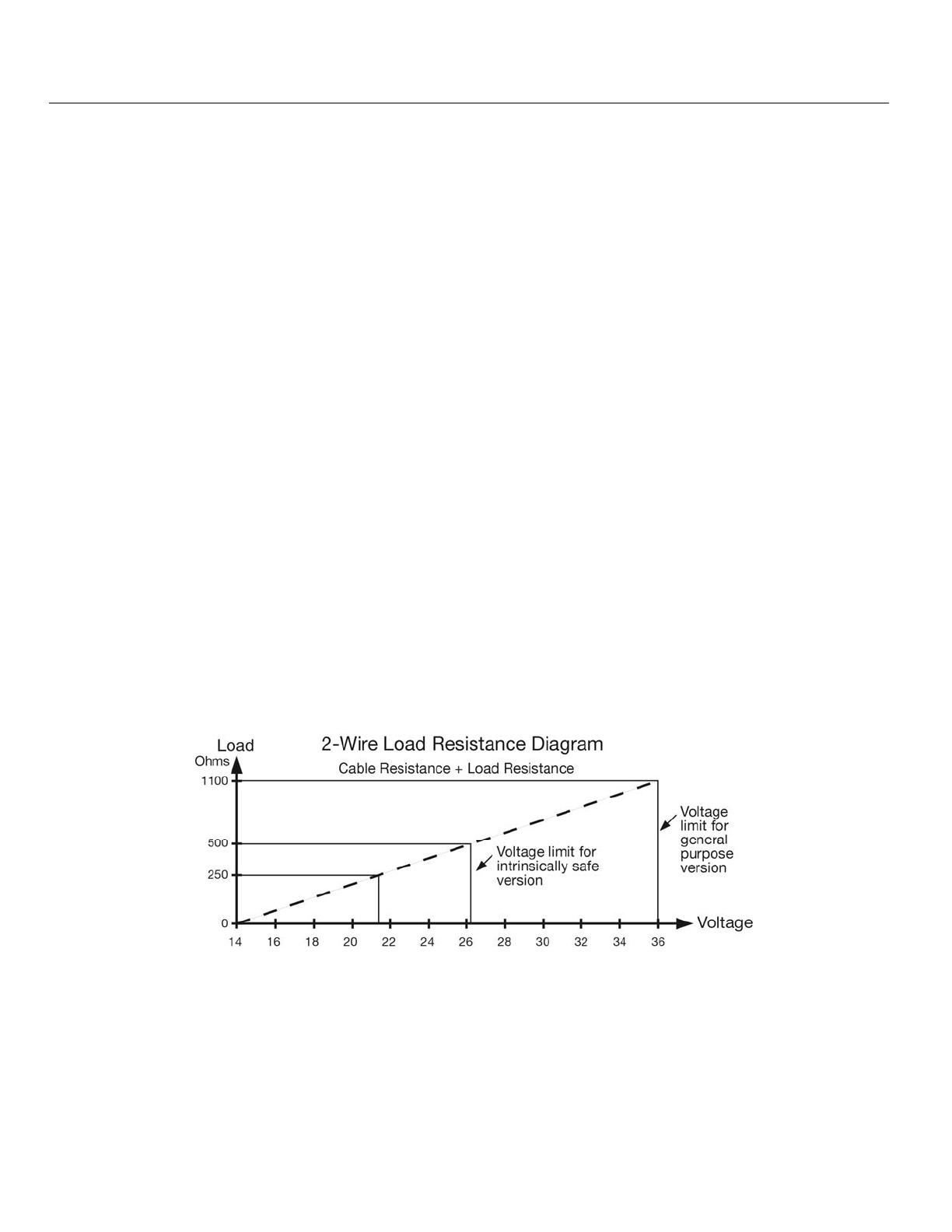
Load Resistance: See chart below

MN301900 Rev B 9 |
Introduction / Table of Contents (continued) Step One
Power:
Power Supply: 24 VDC (21.6 to 26.4 VDC) the same two-wire connection cable carries power
supply and current signal.
Power Consumption: 22.5mA maximum
Ripple Allowed:
<100Hz: <1V
100 to 100 KHz: <10mV
Enclosure Rating: LR11, LR16, LR21, LR26: ........................... IP67 (NEMA 6)
LR31: ........................................................... IP68 (NEMA 6P)
Cable Connection: Standard 2-wire shielded cable with earth ground wire and outside diameter of 5-
9mm is recommended.
Cable Length (LR31 only): 10m (32.8’) standard /
15m (49.2’) maximum length between LR31 and LR98
Cable Entry/Plug: LR11, LR16, LR21, LR26: ..... One cable entry (½” NPT with adapter, M20x1.5)
LR31: ..................................... One cable entry (1” NPT)
Accuracy Charts
| 10 MN301900 Rev B
Introduction / Table of Contents (continued) Step One
Accuracy Charts

MN301900 Rev B 11 |
Introduction / Table of Contents (continued) Step One
Communication: FCC (US)
Part 15.209, Class A: LR11, LR16 (2” horn) and LR26 series can only be installed
on metal or reinforced concrete tanks.
Part 15.256, Class B: LR16 (3” & 4” horn), LR21 & LR31 series can be installed
on any tank material.
Compliance: The equipment complies with the following standards:
IEC: 60079-0:2011 & 60079-11:2011
EN: 60079-0:2012 & 60079-11:2012
RoHS
This product is an intrinsically safe version (Ex ia IIC T6…T3 Ga) with stainless steel
housing. All electric circuits are fully encapsulated in the internal enclosure, where no
conductive parts will contact with flammable gas. Two-Wire system in service, the power
of the product is from safety barrier limited at:
U
i
= 26.4V I
i
= 114mA P
i
= 0.752W C
i
= 0 L
i
= 51µH
A safety barrier should be placed between power source and instrument for intrinsically
safe version. All connection cables must be screened with maximum length of 500m
(stray capacitor ≤ 0.1 µF/Km and stray inductance ≤ 1mH/Km). The level measurement
instrument must be connected to ground potential and unapproved supplemental devices
are not allowed to use.
Application conditions:
Maximum process temperature
Temp. class T6 T5 T4 T3
Ta (max.)
60 °C 60°C 95°C 130°C 180°C
65 °C ----- 70°C 130°C 180°C
70 °C ----- 70°C 130°C 180°C
85 °C ----- ----- 130°C 180°C
Pressure for electronic housing 11.5 psi (80kPa) to 16.0 (110kPa).
Ambient temperature: T6: -20°C ≤ Ta ≤ 60°C
T5: -20°C ≤ Ta ≤ 70°C
T4: -20°C ≤ Ta ≤ 85°C
T3: -20°C ≤ Ta ≤ 85°C
Cable Connection:
This product shall be used with certified IECEx and ATEX cable glands and block plugs. The cable
used for “ia” terminal shall be in compliance with the requirement of EN/IEC 60071-14 clause.
Additional requirements for types of protection “I” – intrinsic safety. It’s installing and operation
instructions should be observed if other cable glands are used.
Care should be taken with the cable glands which should be matched to the cable used outside
diameter property; see mark of cable gland for the outer diameter of being cable used.
In order to ensure the required minimum degree of protection, the bolts of cable glands, blanking plug
and relevant sealing bolts are to be tighten down.

| 12 MN301900 Rev B
Introduction / Table of Contents (continued) Step One
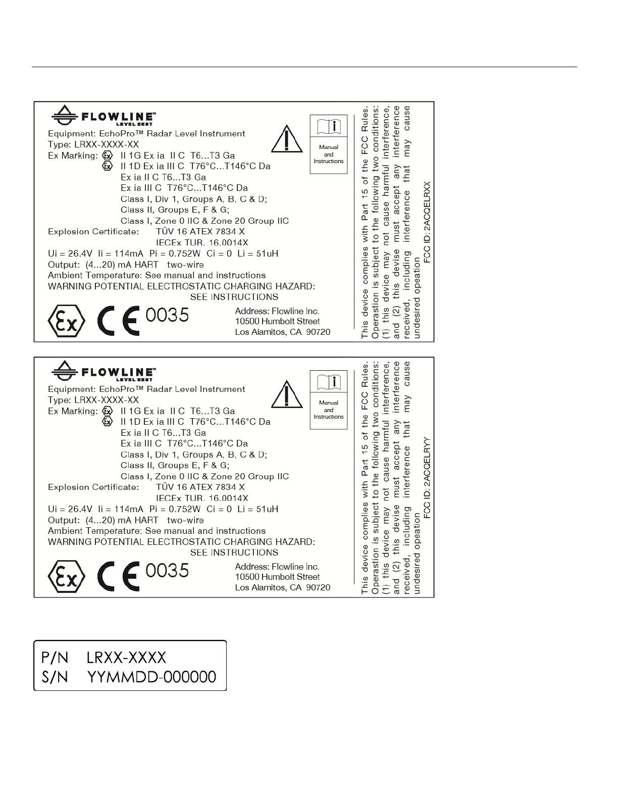
INTRINSICALLY SAFE CONTROL DRAWING 301901
Intrinsically Safe Approvals:
Intrinsic Safe:
North America: Class I, Div.1, Groups A, B, C, D; Class II, Div.1, Groups E, F, G; (T6…T3)
(
c
CSA
us
) Class I, Zone 0 AEx ia IIC (T6…T3) Ga
Zone 20 AEx ia IIIC (T76°C to T146°C) Da
Ex ia IIC (T6…T3) Ga
Ex ia IIIC (T76°C to T146°C) Da
ATEX: II 1G Ex ia II C T6…T3 Ga;
(TUV) II 1D Ex ia IIIC T76°C…T146°C
IECEx: Ex ia II C T6…T3 Ga;
(TUV) Ex ia III C T76°C…T146°C Da
General: CE, RoHS
Intrinsically Safe Entity Parameters:
U
i
= 26.4V; I
i
= 114 mA; P
i
= 0.752W; C
i
= 0; L
i
= 51 μH
MN301900 Rev B 13 |
Introduction / Table of Contents (continued) Step One
LABELS FOR INTRINSIC SAFETY
Part Number Label
| 14 MN301900 Rev B
Introduction / Table of Contents (continued) Step One
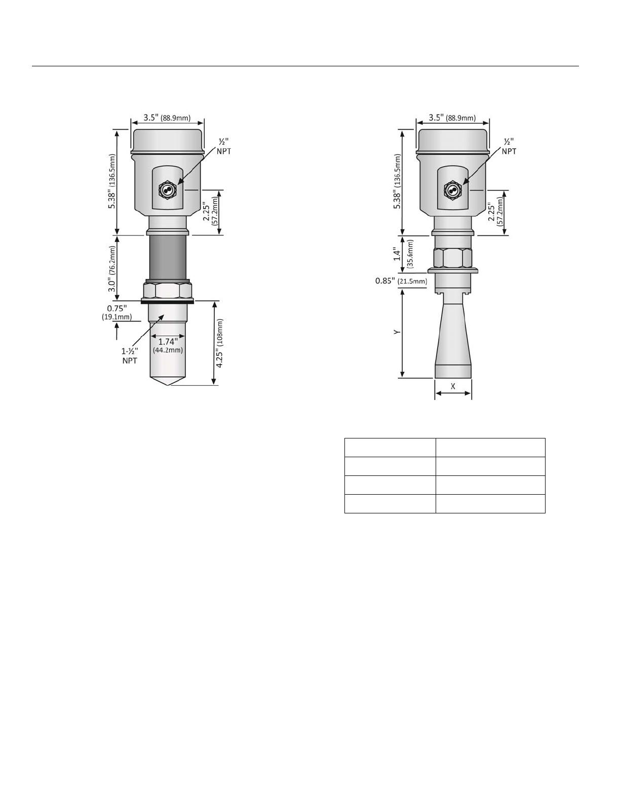
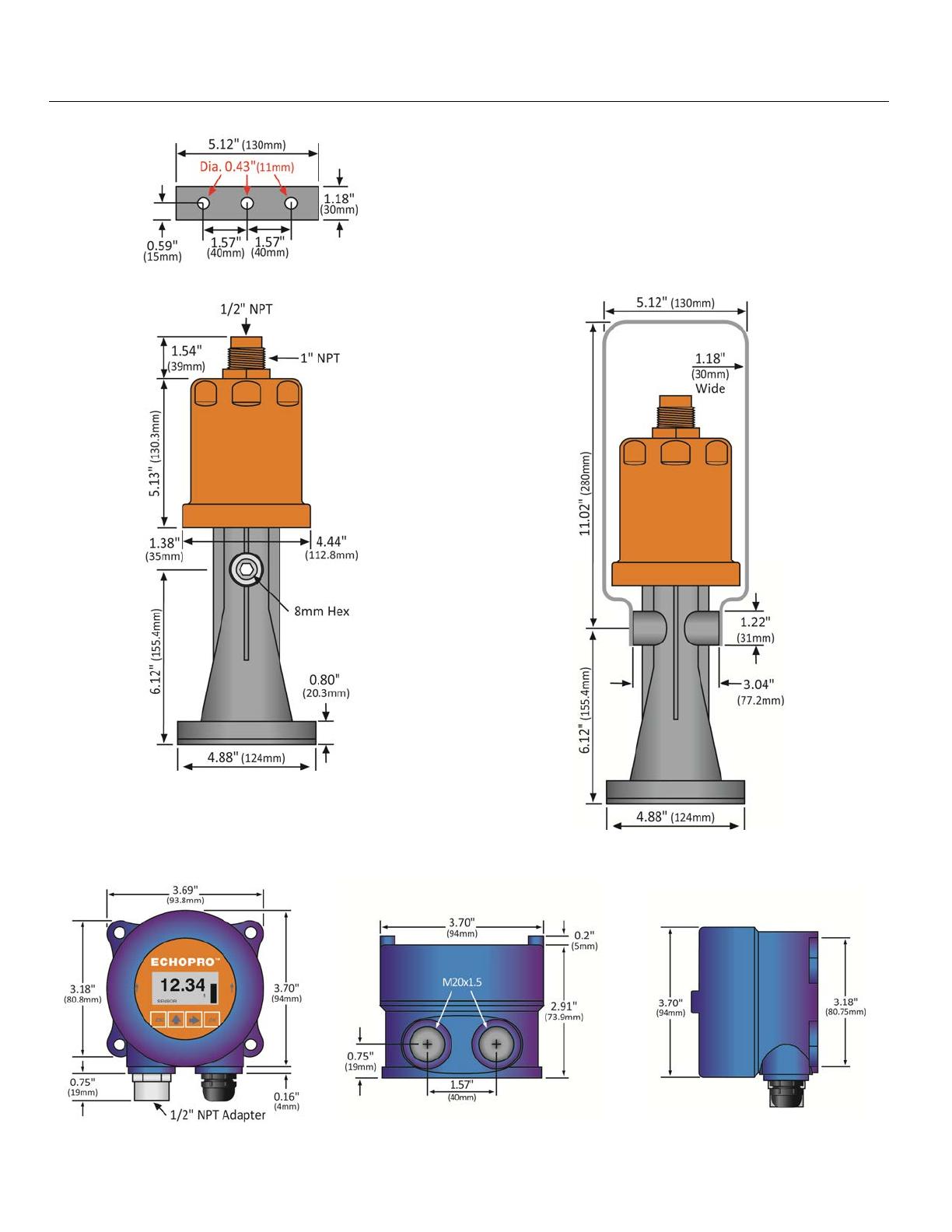
DIMENSIONS
LR11 Series
LR16 Series (Threaded)
LR16 Series (Threaded)
Antenna Dimensions
Diameter (X) Length (Y)
2” (48mm) 5.51” (140mm)
3” (78mm) 8.94” (227mm)
4” (98mm) 11.34” (288mm)

MN301900 Rev B 15 |
Introduction / Table of Contents (continued) Step One
LR21 Series
LR26 Series
LR21 Series Flange / Antenna
Dimensions
LR26 Series Flange / Antenna
Dimensions
Flange
(A)
Diameter
(B)
Thickness
(C)
Length
(D)
3”
ANSI
7.5”
(190.5mm)
0.88”
(22.3mm)
9”
(228.6mm)
4”
ANSI
9.0”
(228.6mm)
0.88”
(22.3mm)
10.5”
(266.7mm)
Flange
(A)
Diameter
(B)
Thickness
(C)
Length
(D)
4”
ANSI
9.0”
(228.6mm)
0.57”
(14.5mm)
5.71”
(145mm)
6”
ANSI
11.0”
(279.4mm)
0.63”
(16.1mm)
9.75”
(247.7mm)
| 16 MN301900 Rev B
Introduction / Table of Contents (continued) Step One
LR31 Series Bracket (Top View)
LR31 Series (Side View A)
LR31 Series (Side View B)
LR98 Series Display
(Front View)
LR98 Series Display
(Bottom View)
LR98 Series Display
(Side View)
Note: Both conduit ports feature M20x1.5 threads. LR98 ships with Liquid Tight Fitting (LM90-1051) and
LR97-S003 Adapter (½” FNPT to M20x1.5). Use the adapter to interface to any ½” MNPT connection.

MN301900 Rev B 17 |
Introduction / Table of Contents (continued) Step One
SAFETY PRECAUTIONS
About this Manual: PLEASE READ THE ENTIRE MANUAL PRIOR TO INSTALLING OR USING THIS
PRODUCT. This manual includes information on the EchoPro
®
Radar Level Transmitter from FLOWLINE.
Please refer to the part number located on the sensor label to verify the exact model, which you have
purchased.
User’s Responsibility for Safety: Flowline manufactures a broad range of level sensing technologies.
While each of these sensors is designed to operate in a wide variety of applications, it is the user’s
responsibility to select a sensor model that is appropriate for the application, install it properly, perform tests of
the installed system, and maintain all components. The failure to do so could result in property damage or
serious injury.
Proper Installation and Handling: Only professional staff should install and/or repair this product. Never
over tighten the sensor within the fitting. Always check for leaks prior to system start-up.
Wiring and Electrical: A supply voltage of 16 to 26 VDC is used to power the EchoPro
®
. Electrical wiring
of the sensor should be performed in accordance with all applicable national, state, and local codes.
Material Compatibility: The enclosure is made of either Aluminum or 316 Stainless Steel (refer to sensor
part number). The antenna is made of Stainless Steel (SS), Polytetrafluoroethylene (PTFE), Perfluoroalkoxy
Alkane (PFA) or Nylon (PA66) with a Viton seal (refer to sensor part number). Make sure that the model, which
you have selected, is chemically compatible with the application media.
Enclosure: The sensor housing is liquid-resistant, but is not designed to be operational when immersed
(LR31 series is designed for submersion but will not provide a true level reading while submersed). Mount the
sensor in such a way that the enclosure and antenna do not come into contact with the application media under
normal operational conditions. The enclosure has a cover that provides access to the push button display
module and terminal strip for wiring. To open the enclosure, you will need to twist the cover counter-clockwise.
Before closing the enclosure, make sure that the enclosure gasket is properly seated, and that any conduit
fittings, cable connectors or plugs are installed correctly and sealed. Note: If using the Flowline LM90-1001
(liquid tight fitting) on the ½” conduit, the cable minimum is 0.170” (4.3mm) and the maximum is 0.450”
(11.4mm).
Make a Fail-Safe System: Design a fail-safe system that accommodates the possibility of sensor and/or
power failure. FLOWLINE recommends the use of redundant back-up systems and alarms in addition to the
primary system.
Flammable, Explosive or Hazardous Applications: EchoPro
®
is approved for use within intrinsically
safe applications and is intended for use within classified hazardous environments.
Handling Static-Sensitive Circuits and Devices: When handling the instrument, the technician should
follow the below guidelines to reduce the possibility of an electrostatic charge build-up on the technician’s body
from being transferred to the electronic part. Always touch a known good ground source before handling a part.
This should be repeated while handling the part and more frequently after sitting down from a standing position,
sliding across the seat or walking a distance. Avoid touching electrical terminals of the part unless making
connections. DO NOT open the unit cover until it is time to work on the part.

| 18 MN301900 Rev B
Getting Started Step Two
SETUP OVERVIEW
The below highlights the initial steps in setting up your sensor for operation.
1. Part Number (Section Two)
1. Prior to purchasing the sensor, you may have submitted a Level Application Questionnaire
(www.flowline.com/LAQ), which based upon the information provided, may have resulted in a
suggested part number. Where so, confirm that the suggested part number matches the part
number of the purchased sensor. If any of the above does not match and/or meet your
application requirements, please contact your distributor.
2. Install Sensor (Section Three)
1. Information on the location and mechanical installation of the sensor.
3. Wire Sensor (Section Four)
1. Information on the electrical wiring and power requirements of the sensor.
4. Basic Configuration Using Display (Section Five)
1. Begin by measuring the tank for all key dimensions.
a. Accuracy in measurement will result in accuracy of sensor performance.
2. Set the Units of Measurement for the sensor.
a. Units can be configured in basic engineering units of length: Feet, Meters
3. Set the Sensor Height for the sensor in the tank.
a. This is the 4mA setting for the output.
4. Set the Fill-Height for the sensor in the tank.
a. This is the 20mA setting for the output.
5. Set the Max. Range (Maximum Range or MaxR) for the sensor in the tank.
a. The sensor will ignore any echo signal returns beyond this setting.
6. Set the Dead Band (Minimum Range or MinR) for the sensor in the tank.
a. The sensor will ignore any echo signal returns closer than this setting.
7. Check the Echo Curve
a. This is a quick check to determine if the sensor is reading the correct level.

MN301900 Rev B 19 |
Getting Started (continued) Step Two
5. Process Adjustments (Section Six)
1. Information on OPTIONAL adjustments for specific process conditions that may exist in your
application.
a. Fast filling or emptying of liquid.
b. Liquid surface is turbulent or agitated.
c. Foam on the surface of the liquid.
d. Sensor installed in a still well or sight glass.
e. Powder or Dust is present.
f. Low Dielectric material
g. Large Angle of Repose with the material
6. Advanced Adjustments (Section Seven)
1. Reverse 4-20 mA Output
a. Reverses the current output from 4mA @ bottom and 20mA @ top of tank to
20mA @
bottom and 4mA @ top of the tank.
2. Fail-Safe Setting
a. Allows for the presetting of the current output when a sensor failure occurs.
3. Minimum Current Setting
a. Sets the minimum current output for the sensor.
4. HART
®
Operation Mode
a. Sets the address for HART® output upon activating the multi-drop setting.
5. Create a New False Echo Curve
a. A method to map out false echo signal returns within the tank.
6. Update an Existing False Echo Curve
a. A method to update false echo signal returns for a section of the tank that was not
exposed during the creation of the original False Echo Curve.
7. Troubleshooting (Section Eight)
1. Measurement Status
a. Determines the measurement reliability and general status of the sensor.
2. Peak Values
a. Displays the lowest and highest level height that the sensor has measured in distance
(d).
3. Simulation
a. Simulates and helps to determine the accuracy and linearity of the sensor.
4. First Echo Adjustment
a. Increases or decreases the strength of the first echo signal return.
5. Echo Curve Zoom In
a. A method to zoom in and view the Echo Curve over a specific range.
6. False Echo Curve Delete
a. A method to delete a previously saved False Echo Curve from memory.
7. Reset
a. A method to reset the sensor’s configuration to the original factory setting.
| 20
Get
t
PAR
T
Prior
(ww
w
num
b
num
b
L
R
Se
r
The
p
belo
w
appli
c
t
ing Star
t
T
NUMBER
to purc
h
w
.flowline.co
m
b
er. Where
b
er can be f
o
R
11
r
ies
L
S
p
art number
w
part num
b
c
ation requi
r
t
ed (cont
h
asing the
m
/LAQ). B
a
so, confirm
o
und on the
L
R16
eries
will indicat
e
b
er descripti
o
r
ements, pl
e
LR11
LR16
inued)
sensor,
y
a
sed upon
t
that the su
g
outside lab
e
LR21
Series
e
the size an
o
n for speci
e
ase contact
- 5
4
Housi
5
-S
P
r
4
-
5
0
Housi
n
5
- S
t
Pr
o
0
y
ou may
t
he informa
g
gested par
t
e
l of the sen
s
LR26
Series
d type of m
o
fic informati
your distrib
2
1
-
ng Material
tainless Ste
r
ocess Con
n
- PFA - 1
½
Approval
2
-
A
TE
X
Outp
u
1
-
4
2
1
-
n
g Material
t
ainless Ste
e
o
cess Conn
- Thread 1
Approval
2
-
A
TE
X
Outpu
t
1
- 4-
A
2
3
4
have su
b
tion provid
e
t
number m
a
s
o
r
as sho
w
LR31
Series
o
unting fittin
on. If any
o
utor.
0 0
el Intrinsical
n
ection
½
" NPT
X
/ IECEx /
u
t
4
-20 mA
0
-
0
e
l Intrinsicall
ection
½" NPT
X
/ IECEx /
H
t
20 mA
A
ntenna S
h
2
- 2" (48
m
3
- 3" (78
m
4
- 4" (98
m
Flange
S
0
- Thr
e
b
mitted a
e
d, it may
h
a
tches the
p
w
n below:
g required f
o
o
f the abov
e
ly Safe
HazLoc
0
y Safe
H
azLoc
h
ape
m
m) Horn
m
m) Horn
m
m) Horn
S
ize
e
aded Conn
Level Ap
p
h
ave result
e
p
art number
o
r installing
e
does not
m
ection
M
p
lication
Q
e
d in a su
g
of the sens
the senso
r
.
m
atch and/
o
N301900 Rev B
Step Two
Q
uestionnair
e
g
gested pa
r
or. The pa
r
Refer to th
e
o
r meet you
e
r
t
r
t
e
r
/