Page is loading ...

2
1
43
16 mm
16 mm
Stichlänge
<5mm >5mm
AB
5
Teile-Nr./ Part-No.:
0791 867703
Printed in Federal Republic of Germany
Ausgabe/Edition:
01. 2006
Blatt: 1 von 4
Sheett from
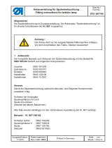
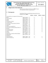
1. Allgemeine Information
1.1 Anbausatz
Der komplette Bausatz zum Anbauen und Einstellen der Reflexlichtschranke mit der Bestell-Nr.:
0867 590074 besteht aus folgenden Komponenten:
Lichtschranke 9815 920023 Kopfdeckel 0667 105164
Halter 0867 490030 Scheibe 1001 009243
Reflexfolie 9815 920024 Linsenschr. 9204 201657
Bef. Schelle 9840 120025 Kabelbinder 9840 121001
Scheibe 9330 000087
Vorsicht Verletzungsgefahr !
Hauptschalter ausschalten!
Bausatz nur bei ausgeschalteter Nähmaschine anbauen.
2. Montage
– Kopfdeckel demontieren.
– Neuen Kopfdeckel 0667 105164 montieren.
– Lichtschranke 1 an Halter 2 mit den Linsen-
schrauben 3 anschrauben.
– Anschlusskabel in die Zugentlastung des Halters
einfügen.
– Halter 2 mit Lichtschranke an den Kopfdeckel mit
zwei Linsenschrauben und Scheiben
anschrauben.
– Anschlusskabel durch die Schelle 4 führen und
mit Linsenschraube und Scheibe am Kopfdeckel
anschrauben.
– An der Rückseite des Nähkopfes zum
Kabelkanal führen und mit zwei Kabelbindern
fixieren.
– Stecker 6 an die Leiterplatte des Nähkopfes
anschliessen (siehe Abbildung).
–
Reflexfolien 5 (siehe Abbildung) aufkleben.
A = für Stichlänge £ 5mm
B = für Stichlänge ³ 5mm
Anbauanleitung Reflexlichtschranke
Instructions for fitting the reflecting light barrier
Bausatz / Kit 0867 590074
6

3. Reflexlichtschranke
3.1 Einstellung und Ausrichtung
- Die Einstellung ist abhängig vom Abstand der Lichtschranke zur Reflexionsfolie.
- Die Ausrichtung wird mittels eines sichtbaren Lichtpunktes auf der Reflexionsfläche
vorgenommen.
3.2 Parametereinstellungen für Lichtschrankenfunktion
Efka Steuerung 6F82FA , DA 82GA , DA 321G
Parameter Nr.
Funktion Einstellung auf
009 Lichtschranke ON
*1)
004 Ausgleichstich, langer Stich
010 Ausgleichstich, kurzer Stich
(normale Stichlänge)
* 1) Mit EFKA Bedienfeld V820 mit Taste “ 3 ”
- Lichtschranke OFF = kein Pfeil über Taste “ 3 ”
- Lichtschranke ON = rechter Pfeil über Taste “ 3 ”
Anbauanleitung Reflexlichtschranke
Instructions for fitting the reflecting light barrier
Bausatz / Kit 0867 590074
Teile-Nr./ Part-No.:
0791 867703
Printed in Federal Republic of Germany
Ausgabe/Edition:
01. 2006
Blatt: 2 von 4
Sheet: from

Teile-Nr./ Part-No.:
0791 867703
Printed in Federal Republic of Germany
Ausgabe/Edition:
01. 2006
Blatt: 3 von 4
Sheett from
1. General information
1.1 Mounting kit
The complete kit for mounting and adjusting the reflected light barrier with the order number
0867 590074 consists of the following components:
light barrier 9815 920023 head cover 0667 105164
holder 0867 490030 washer 1001 009243
reflecting foil 9815 920024 oval head screw 9204 201657
fastening clamp 9840 120025 cable tie 9840 121001
washer 9330 000087
Caution: Risk of injury !
Switchthemainswitchoff!
Mount the kit only with the sewing machine switched off.
2. Assembly
– Remove the head cover.
– Mount new head cover 0667 105164.
– Screw light barrier 1 on holder 2 with the oval
head screws 3.
– Place the connecting cable in the strain relief of
the holder.
– Screw holder 2 with light barrier on the head
cover with two oval head screws and washers.
– Guide the connecting cable through clamp 4
and screw it on the head cover with oval head
screw and washer.
– Guide the cable to the cable duct at the back
side of the sewing head and fix it with two cable
ties.
– Connect plug 6 to the printed circuit board of the
sewing head (see illustration).
–
Stick on reflecting foils 5 (see illustration).
A = for stitch length £ 5mm
B = for stitch length ³ 5mm
Anbauanleitung Reflexlichtschranke
Instructions for fitting the reflecting light barrier
Bausatz / Kit 0867 590074
2
1
43
16 mm
16 mm
Stichlänge
<5mm >5mm
AB
5
6

3. Reflecting light barrier
3.1 Adjustment and alignment
- The adjustment is dependent on the distance between light barrier and reflecting foil.
- The alignment is made by means of a visible light spot on the reflecting area.
3.2 Parameter settings for light barrier function
Efka control 6F82FA , DA 82GA , DA 321G
Parameter No.
Function Set to
009 light barrier ON
*1)
004 compensating stitch, long stitch
010 compensating stitch, short stitch
(normal stitch length)
* 1) With EFKA control panel V820 with push button ” 3 ”
- light barrier OFF = no arrow above push button ” 3 ”
- light barrier ON = right arrow above push button ” 3 ”
Anbauanleitung Reflexlichtschranke
Instructions for fitting the reflecting light barrier
Bausatz / Kit 0867 590074
Teile-Nr./ Part-No.:
0791 867703
Printed in Federal Republic of Germany
Ausgabe/Edition:
01. 2006
Blatt: 4 von 4
Sheet: from
/

