
e-mail: [email protected]
For latest product manuals:
www.omegamanual.info
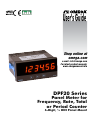
DPF20 Series
Panel Meter for
Frequency, Rate, Total
or Period Counter
6-Digit,
1
⁄8 DIN Panel Mount
TM
Shop online at
omega.com
User’s Guide

2
www.omega.com [email protected]
The information contained in this document is believed to be correct, but OMEGA accepts no liability for any errors it contains, and
reserves the right to alter specications without notice.
Servicing North America:
U.S.A. Omega Engineering, Inc.
Headquarters: Toll-Free: 1-800-826-6342 (USA & Canada only)
Customer Service: 1-800-622-2378 (USA & Canada only)
Engineering Service: 1-800-872-9436 (USA & Canada only)
Tel: (203) 359-1660 Fax: (203) 359-7700
e-mail: [email protected]
For Other Locations Visit omega.com/worldwide

3
OMEGA’s policy is to make running changes, not model changes, whenever an improvement is possible. This affords
our customers the latest in technology and engineering.
OMEGA is a registered trademark of OMEGA ENGINEERING, INC.
© Copyright 2018 OMEGA ENGINEERING, INC. All rights reserved. This document may not be copied, photocopied,
reproduced, translated, or reduced to any electronic medium or machine-readable form, in whole or in part, without the
prior written consent of OMEGA ENGINEERING, INC.
FOR WARRANTY RETURNS, please have the
following information available BEFORE
contacting OMEGA:
1. Purchase Order number under which the
product was PURCHASED,
2. Model and serial number of the product under
warranty, and
3. Repair instructions and/or specific problems
relative to the product.
FOR NON-WARRANTY REPAIRS,
consult OMEGA
for current repair charges. Have the following
information available BEFORE contacting OMEGA:
1. Purchase Order number to cover the COST
of the repair,
2. Model and serial number of the product, and
3. Repair instructions and/or specific problems
relative to the product.
RETURN REQUESTS/INQUIRIES
Direct all warranty and repair requests/inquiries to the OMEGA Customer Service Department.
BEFORE RETURNING ANY PRODUCT(S) TO OMEGA, PURCHASER MUST OBTAIN AN AUTHORIZED
RETURN (AR) NUMBER FROM OMEGA’S CUSTOMER SERVICE DEPARTMENT (IN ORDER TO AVOID
PROCESSING DELAYS). The assigned AR number should then be marked on the outside of the return
package and on any correspondence.
The purchaser is responsible for shipping charges, freight, insurance and proper packaging to prevent
breakage in transit.
WARRANTY/DISCLAIMER
OMEGA ENGINEERING, INC. warrants this unit to be free of defects in materials and workmanship
for a period of 61 months from date of purchase. OMEGA’s WARRANTY adds an additional one (1)
month grace period to the normal five (5) year product warranty to cover handling and shipping
time. This ensures that OMEGA’s customers receive maximum coverage on each product.
If the unit malfunctions, it must be returned to the factory for evaluation. OMEGA’s Customer Service
Department will issue an Authorized Return (AR) number immediately upon phone or written request.
Upon examination by OMEGA, if the unit is found to be defective, it will be repaired or replaced at no
charge. OMEGA’s WARRANTY does not apply to defects resulting from any action of the purchaser,
including but not limited to mishandling, improper interfacing, operation outside of design limits,
improper repair, or unauthorized modification. This WARRANTY is VOID if the unit shows evidence of
having been tampered with or shows evidence of having been damaged as a
result of excessive corrosion; or current, heat, moisture or vibration; improper
specification; misapplication; misuse or other operating conditions outside of
OMEGA’s control. Components in which wear is not warranted, include but are not
limited to contact points, fuses, and triacs.
OMEGA is pleased to offer suggestions on the use of its various products. However,
OMEGA neither assumes responsibility for any omissions or errors nor
assumes
liability for any damages that result from the
use of its products
in accordance with information provided by OMEGA, either verbal or
written. OMEGA warrants only that the parts manufactured by it will be as
specified and free of defects. OMEGA MAKES NO OTHER WARRANTIES OR
REPRESENTATIONS OF ANY KIND WHATSOEVER, EXPRESS OR IMPLIED, EXCEPT
THAT OF TITLE, AND ALL IMPLIED WARRANTIES INCLUDING ANY WARRANTY OF
MERCHANTABILITY AND FITNESS FOR A PARTICULAR PURPOSE ARE HEREBY
DISCLAIMED. LIMITATION OF LIABILITY: The remedies of purchaser set forth herein are
exclusive, and the total liability of OMEGA with respect to this order, whether
based on contract, warranty, negligence, indemnification, strict liability or otherwise,
shall not exceed the purchase price of the component upon which liability
is based. In no event shall OMEGA be liable for consequential, incidental or special damages.
CONDITIONS: Equipment sold by OMEGA is not intended to be used, nor shall it be used: (1) as a
“Basic Component” under 10 CFR 21 (NRC), used in or with any nuclear installation or activity; or (2)
in medical applications or used on humans. Should any Product(s) be used in or with any nuclear
installation or activity, medical application, used on humans, or misused in any way, OMEGA assumes
no responsibility as set forth in our basic WARRANTY / DISCLAIMER language, and, additionally,
purchaser will indemnify OMEGA and hold OMEGA harmless from any liability or damage whatsoever
arising out of the use of the Product(s) in such a manner.

4
DPF20
Frequency, rate, total or period counter
Instruction Manual
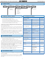
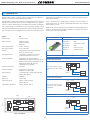
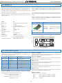
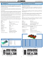
1. Panel meter DPF20
Counter, ratemeter and periodmeter, 96 x 48 mm (1/8 DIN)
Panel meter 96 x 48 mm (1/8 DIN) and 6 digits with 14 mm digit height,
congurable with 5 impulse counter modes (see secon 1.2), 2 rate-
meter modes (see secon 1.3) and a 1 periodmeter mode (see secon
1.4).
Highly congurable, accepts all types of sensors (NPN, PNP, push-
pull, Namur, inducve, pick-up, mechanical, TTL, CMOS, ...) including
quadrature signals (single and bidireconal encoder signals).
Reading from 999999 to -199999 with decimal point, scalable read-
ing with congurable mulplier factor (1 to 999999) and congurable
divider factor (1 to 999999). Includes internal pull-up and pull-down
resistors, congurable trigger levels, detecon by rising or falling edge,
excitaon voltage congurable from 5 Vdc to 18 Vdc.
Opons for output and control with 1, 2 and 3 relays, transistor out-
puts, SSR drive controls, isolated analog outputs, communicaons in
Modbus RTU, RS-485 ASCII and RS-232. Special opons with 4 and 6
relay outputs.
Independent alarms congurable as maximum or minimum, with 1 or
2 setpoints per alarm, hysteresis, independent acvaon and deac-
vaon delays and control for inverted relay.
Front protecon IP65. Connecons by plug-in screw terminals. For in-
dustrial applicaons.
• ‘Fast access’ menu to selected funcons, accessible with key UP (5)
(see secon 1.19.12)
• Funcon ‘On power up’ for system protecon on rst ‘cold’ start-up
or automac reset (see secon 1.19.15)
• Special ‘FAST’ mode for fast counng applicaons (see secon 1.16)
• Special ‘SLOW’ mode for slow ratemeter applicaons (low frequency
applicaons) (see secon 1.15)
• Direct conguraon for most usual sensor, at the ‘SnSr / Auto’ menu
(see secon 1.19.10)
• Funcon ‘Trigger Sense’ helps to detect the correct trigger level (see
secon 1.13)
Mulple display lters, memory for maximum and minimum reading,
password protecon, 5 brightness levels.
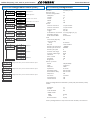
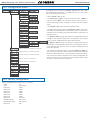
Index
1. Panel meter DPF20 . . . . . . . . . . . . . . . . . . . . . . . 4
1.1 How to order . . . . . . . . . . . . . . . . . . . . . . . . 5
1.2 Impulse counter modes . . . . . . . . . . . . . . . . . . 5
1.3 Ratemeter modes. . . . . . . . . . . . . . . . . . . . . . 5
1.4 Periodmeter mode . . . . . . . . . . . . . . . . . . . . . 5
1.5 Funcons included . . . . . . . . . . . . . . . . . . . . . 5
1.6 Front view . . . . . . . . . . . . . . . . . . . . . . . . . . 6
1.7 Power connecons . . . . . . . . . . . . . . . . . . . . . 6
1.8 Sensor conguraon and connecons . . . . . . . . . . 6
1.9 Rear view . . . . . . . . . . . . . . . . . . . . . . . . . . 6
1.10 Signal connecons . . . . . . . . . . . . . . . . . . . . 6
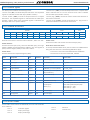
1.11 Technical specicaons . . . . . . . . . . . . . . . . . . 7
1.12 Mechanical dimensions (mm) (in) . . . . . . . . . . . . 7
1.13 Funcon ‘Trigger Sense’ . . . . . . . . . . . . . . . . . 8
1.14 Funcon ‘cycle counter’ . . . . . . . . . . . . . . . . . 8
1.15 ‘SLOW’ mode . . . . . . . . . . . . . . . . . . . . . . . 8
1.16 ‘FAST’ mode . . . . . . . . . . . . . . . . . . . . . . . . 8
1.17 How to operate the menus. . . . . . . . . . . . . . . . 9
1.18 Messages and errors . . . . . . . . . . . . . . . . . . . 9
1.19 Conguraon menu. . . . . . . . . . . . . . . . . . . . 10
1.19.1 Inial set-up . . . . . . . . . . . . . . . . . . . . . .10
1.19.2 Conguraon for ‘cn.1’ . . . . . . . . . . . . . . . .10
1.19.3 Conguraon for ‘cnq.2’ . . . . . . . . . . . . . . . 11
1.19.4 Conguraon for ‘cnI.3’. . . . . . . . . . . . . . . . 11
1.19.5 Conguraon for ‘cnc.4’ . . . . . . . . . . . . . . . 11
1.19.6 Conguraon for ‘cnd.5’ . . . . . . . . . . . . . . . 12
1.19.7 Conguraon for ‘rt.6’ . . . . . . . . . . . . . . . . 12
1.19.8 Conguraon for ‘rtq.7’. . . . . . . . . . . . . . . . 12
1.19.9 Conguraon for ‘Prd.8’ . . . . . . . . . . . . . . . 13
1.19.10 Sensor conguraon. . . . . . . . . . . . . . . . . 13
1.19.11 Alarms . . . . . . . . . . . . . . . . . . . . . . . . 15
1.19.12 Fast access . . . . . . . . . . . . . . . . . . . . . . 16
1.19.13 Super fast access . . . . . . . . . . . . . . . . . . . 16
1.19.15 Menu ‘On Power Up’ . . . . . . . . . . . . . . . . 16
1.19.14 Menu ‘Key LE’ . . . . . . . . . . . . . . . . . . . . 16
1.19.16 Menus ‘Overrange / underrange’. . . . . . . . . . 17
1.19.17 Le zeros . . . . . . . . . . . . . . . . . . . . . . .17
1.19.18 Vexc. control . . . . . . . . . . . . . . . . . . . . .17
1.19.19 Funcon ‘Password’ . . . . . . . . . . . . . . . . .17
1.19.20 Factory reset . . . . . . . . . . . . . . . . . . . . .17
1.19.21 Firmware version. . . . . . . . . . . . . . . . . . . 17
1.19.22 Brightness . . . . . . . . . . . . . . . . . . . . . . 17
1.19.23 Access to oponal modules . . . . . . . . . . . . . 17
1.20 Full conguraon menu . . . . . . . . . . . . . . . . . 18
1.21 Factory conguraon . . . . . . . . . . . . . . . . . . .21
1.22 To access the instrument . . . . . . . . . . . . . . . . .22
1.23 Modular system . . . . . . . . . . . . . . . . . . . . . .22
1.24 Precauons on installaon . . . . . . . . . . . . . . . .23
1.25 CE declaraon of conformity . . . . . . . . . . . . . . . 23
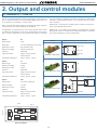
2. Output and control modules . . . . . . . . . . . . . . . . . 24
2.1 Módules R1, T1 and SSR . . . . . . . . . . . . . . . . . .24
2.2 Module AO . . . . . . . . . . . . . . . . . . . . . . . . . 25
2.2.1 Conguraon menu . . . . . . . . . . . . . . . . . . 26
2.2.2 Error codes . . . . . . . . . . . . . . . . . . . . . . . 26
2.2.3 Factory conguraon . . . . . . . . . . . . . . . . . . 26
2.3 Module RTU. . . . . . . . . . . . . . . . . . . . . . . . . 27
2.3.1 Accessible registers . . . . . . . . . . . . . . . . . . . 27
2.3.2 Conguraon menu . . . . . . . . . . . . . . . . . . 28
2.3.3 Excepon codes. . . . . . . . . . . . . . . . . . . . . 28
2.3.4 Descripon and example for Modbus RTU registers 29
2.4 Module S4. . . . . . . . . . . . . . . . . . . . . . . . . . 30
2.4.1 Accessible registers . . . . . . . . . . . . . . . . . . . 30
2.4.2 Conguraon menu . . . . . . . . . . . . . . . . . . 31
2.4.3 Factory conguraon . . . . . . . . . . . . . . . . . . 31
2.4.4 Frame types . . . . . . . . . . . . . . . . . . . . . . .32
2.4.5 Frame structure . . . . . . . . . . . . . . . . . . . . . 32
2.4.6 Error codes . . . . . . . . . . . . . . . . . . . . . . . 32
2.4.7 Frame examples. . . . . . . . . . . . . . . . . . . . . 33
2.4.8 CRC calculaon . . . . . . . . . . . . . . . . . . . . .33
2.5 Module S2. . . . . . . . . . . . . . . . . . . . . . . . . . 34
2.6 Modules R2, R4 and R6. . . . . . . . . . . . . . . . . . . 34
2.6.1 Conguraon menu . . . . . . . . . . . . . . . . . . 35
2.6.2 Factory conguraon . . . . . . . . . . . . . . . . . . 35
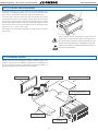
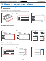
3. How to open and close. . . . . . . . . . . . . . . . . . . . . 36
3.1 How to open the housing . . . . . . . . . . . . . . . . . 36
3.2 How to close the housing . . . . . . . . . . . . . . . . . 37

5
DPF20
Frequency, rate, total or period counter
Instruction Manual
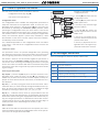
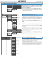
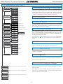
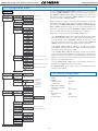
1.1 How to order
1.2 Impulse counter modes
The instrument allows for 5 selectable impulse counter modes :
• Counter (‘cn.1’) (see secon 1.19.2)
• Counter quadrature (‘cnq.2’) (see secon 1.19.3)
• Counter with inhibion (‘cnI.3’) (see secon 1.19.4)
• Counter with control add / substract (‘cnc.4’) (see secon 1.19.5)
• Counter dierenal (‘cnd.5’) (see secon 1.19.6)
Congurable up or down counng, ‘reset’ at rear terminals, front key
and/or at alarm acvaon. Congurable ‘Preset’ value. Relay acva-
on and deacvaon delays.
Alarm funcons with ‘return to preset’ or ‘reset to 0’ generate cycles
of counng (instrument counts from ‘preset’ value to alarm value
in never ending cycle). The instrument provides memory of cycles
counter.
Scalable reading with congurable mulplier factor (1 to 999999)
and congurable divider factor (1 to 999999). Memory retenon in
case or power loss. Retains conguraon and last reading.
Counng frequency up to 250 KHz, in ‘FAST’ mode (see secon 1.16).
1.3 Ratemeter modes
In ratemeter mode the reading is proporonal to the measured fre-
quency. The instrument allows for 2 selectable ratemeter modes :
• Ratemeter (‘rt.6’) (see secon 1.19.7)
• Ratemeter quadrature (‘rtq.7’) (see secon 1.19.8)
The ratemeter mode has a single input channel, with scalable read-
ing. The quadrature ratemeter mode has 2 inpur channels available
for detecon of sense of turn when working with quadrature signals.
Scalable reading with congurable mulplier factor (1 to 999999)
and congurable divider factor (1 to 999999).
For low frequency applicaons, the ‘SLOW’ mode provides the best
response me for each applicaon (see secon 1.15).
Maximum frequency up to 500 KHz and minimum frequency down
to de 0.001 Hz (1 mHz) with ‘SLOW’ mode acve.
Reading is proporonal to the signal period. Scalable reading with
congurable mulplier factor (1 to 999999) and congurable divider
factor (1 to 999999).
For applicaons with long periods (slow frequencies), the ‘SLOW’
mode provides the best response me for each applicaon (see sec-
on 1.15).
1.4 Periodmeter mode
Funcons included Secon
‘Fast access’ yes 1.19.12
‘SLOW’ mode yes, for slow frequencies 1.15
‘FAST’ mode yes, for fast counng 1.16
Mulplier and divider from 1 to 999999 1.19.2
Reset congurable
yes (front, rear and linked
to alarm acvaon)
1.19.14 and
1.10 and
1.19.11
Preset yes 1.19.2
Trigger level congurable 1.19.10
‘Trigger Sense’ funcon helps to set the trigger 1.13
Sensor selecon by menu 1.19.10
Cycle counter 1.14
Retenon memory yes, recovers with power 1.11
‘On Power Up’ yes
1.19.15
Excitaon voltage congurable 1.19.10
Display lters recursive
1.19.7 and
1.19.8 and
1.19.9
Memory max., min., cycles 1.19.12
Password
blocks access to congu-
raon menu
1.19.19
Alarms
double setpoints
acvaon delays
deacvaon delays
hysteresis
inverted relays
locked alarms
1.19.11
Display brightness 5 levels
1.19.22
Table 1 - Funcons included
1.5 Funcons included
DPF20
Model Power Opon 1 Others
HV- -
-
Opon 2
-
Opon 3
-
-R1
(1 relay)
-AO (analog output)
-RTU (Modbus RTU)
-S4 (RS-485)
-S2 (RS-232)
-T1 (1 transistor)
-SSR (1 SSR drive)
- (empty)
-HV (85-265 Vac/dc)
-LV (11/60 Vdc,
24 Vac, 48 Vac)
-NBT (no buons)
-GN (green led)

6
DPF20
Frequency, rate, total or period counter
Instruction Manual
Buon ‘LE’
Earth connecon - Although a
terminal is provided for earth
connecon, this connecon is
oponal. The instrument does
not need earth connecon for
correct operaon nor for com-
pliance with the security regu-
laons.
~
~
+
-
8 9 0
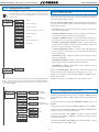
Fuse - To comply with security regulaon 61010-1, add to the power
line a protecon fuse acng as disconnecon element, easily acces-
sible to the operator and idened as a protecon device.
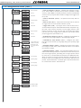
Power ‘H’ fuse 250 mA me lag
Power ‘L’ fuse 400 mA me lag
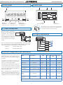
1.7 Power connecons
1.6 Front view
Buon ‘UP’
Logo
Alarms
Units
Buon ‘SQ’
‘Conguraon menu’
(see secon 1.19)
‘Fast access‘
(see secon 1.19.12)
1.8 Sensor conguraon and connecons
Signal
(see secon 1.10)
Opon 1 Opon 2Opon 3
Power
(see secon 1.7)
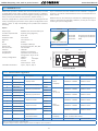
Detail of the plug-in screw terminals provided with
the instrument. The instrument is provided with all
terminals needed, both male and female.
1.9 Rear view
1.10 Signal connecons
Selecng one of the sensors listed at the
‘SnSr’ menu entry, will congure the sen-
sor parameters to the values indicated in
the table.
The table also indicates the typical con-
necons for each type of sensor. Param-
eters can be manually modied.
Connecons are indicated for a single sen-
sor connected to the channel A. For two
sensors (for inhibion control, quadrature
signal, etc) apply the same connecon cri-
teria also to channel B.
Note : indicated values are typical values.
Check the correct specicaons with your
sensor datasheet and adapt the required
conguraon and connecons as needed.
Sensor Connecons Pulls Vexc. Anrrebound
lter
Trigger
Mechanical contact 0 V channel A pull-up no 100 mSec. 2,5 Vdc
Namur channel A Vexc pull-down 9 Vdc no 3,0 Vdc
NPN 2 wires 0 V channel A pull-up 18 Vdc no 2,5 Vdc
NPN 3 wires 0 V channel A Vexc pull-up 18 Vdc no 2,5 Vdc
PNP 2 wires 0 V channel A pull-down 18 Vdc no 2,5 Vdc
PNP 3 wires 0 V channel A Vexc pull-down 18 Vdc no 2,5 Vdc
Push-pull 0 V channel A Vexc no 18 Vdc no 2,5 Vdc
TTL
CMOS
Pick-up
0 V channel A no 5 Vdc no 2,5 Vdc
AC<30 Vp
Inducve
0 V channel A no no no 0 Vdc
Table 2 - Conguraon and connecons for dierent types of sensors.
Front reset
(see secon 1.19.14)
Vexc.
12345
Canal B
Reset
0 V
Canal A

7
DPF20
Frequency, rate, total or period counter
Instruction Manual
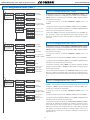
Digits
number of digits 6
led 7 segments led
color red or green
digit height 14 mm
Reading
maximum reading 999999
minimum reading -199999
decimal point congurable X.X.X.X.X.X.
overrange / underrange congurable to ash, reset or preset (see
secon 1.19.16)
display refresh 15 readings / second
memory retenon yes, retains reading value in case of pow-
er loss
Signals accepted NPN, PNP, Namur, pick-up, TTL, induc-
ve, mechanical, quadrature, ...
Max. Vdc at input ±30 Vdc
Input impedance 2K4 with pull-up or pull-down resistor
470K without pull resistor
Accuracy of the quartz ±0.01 %
Thermal dri 20 ppm / ºC
Excitaon voltage congurable
output voltage +18 Vdc, +15 Vdc, +9 Vdc, +5 Vdc
maximum current 70 mA
protecon yes, current limited to 70 mA
Frequencies counter modes (see Table 3)
ratemeter modes (see Table 4)
periodmeter modes (see Table 5)
Power
power ‘H’ 85 to 265 Vac/dc
power ‘L’ 11 to 60 Vdc and 24/48 Vac
isolaon* 2500 Ve with power ‘H’
1500 Ve with power ‘L’
*tested for 60 sec.
consumpon <1.5 W only meter
<4.0 W meter with opons
Conguraon 3 buons front keypad
Front protecon IP65
Output and control opons relays, analog outputs, serial communi-
caons (see secon 2)
Mechanical
mounng panel
connecons plug-in screw terminal
housing material ABS, polycarbonate (V0)
weight <150 grams
front size 96 x 48 mm (1/8 DIN)
panel cut-out 92 x 44 mm
depth from panel 91 mm (including terminals)
Temperature
operaon from 0 to +50 ºC
storage from -20 to +70 ºC
warm-up me 15 minutes
Counter Mode Frequency Secon
Counter
‘FAST’ mode acve max. 250 KHz 1.19.2
normal mode max. 9 KHz 1.19.2
Counter + inhibion max. 9 KHz 1.19.4
Counter + control A/S max. 9 KHz 1.19.5
Counter dierenal max. 9 KHz 1.19.6
Counter
quadrature
mode x1 max. 17 KHz 1.19.3
mode x2 max. 16 KHz 1.19.3
mode x4 max. 11 KHz 1.19.3
Table 3 - Maximum input frequency for counter modes
Ratemeter Mode Frequency Secon
Ratemeter
normal mode
max. 500 KHz
1.19.7
‘SLOW’ mode ac-
ve
max. 200 Hz
min. 1 mHz
1.19.7
Ratemeter
quadrature
mode x1 max. 17 KHz 1.19.8
mode x2 max. 16 KHz 1.19.8
mode x4 max. 11 KHz 1.19.8
Table 4 - Maximum and minimum input frequency for ratemeter modes
Periodmeter Mode Frequency Secon
Periodmeter
normal mode
max. 500 KHz
1.19.9
‘SLOW’ mode ac-
ve
max. 200 Hz
min. 1 mHz
(1000 sec.)
1.19.9
Table 5 - Maximum and minimum input frequency for periodmeter modes
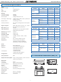
1.12 Mechanical dimensions (mm) (in)
1.11 Technical specicaons
44
92
Panel
cut-out
16
8
75
96
48
(1.89)
(3.78)
(0.63)
(0.31)(2.95)
(1.74)
(3.63)

8
DPF20
Frequency, rate, total or period counter
Instruction Manual
Special working mode for applicaons with low frequency signals.
Applies to ratemeter (‘rt.6’), ratemeter quadrature (‘rtq.7’) and peri-
odmeter (‘Prd.8’). The ‘SLOW’ mode allows to measure slow fre-
quencies down to 1 mHz (0,001 Hz) and is funconal up to 200 Hz.
The ‘SLOW’ mode provides the fastest response me possible for a
given applicaon, calculang the frequency and the period based on
the me between consecuve impulses.
The ‘SLOW’ mode needs to dene the parameter ‘maximum waing
me’ to a value between 1 and 1000 seconds. If this me expires
without a single impulse being received, the reading jumps to ‘0’
(both for ratemeter and periodmeter modes). The ‘GATE’ parameter
is not used if ‘SLOW’ mode is acve.
In ‘ratemeter quadrature’ (‘rtq.7’) mode, the acvaon of the
‘SLOW’ mode calculates the frequency based on the me between
consecuve impulses received on channel A, and calculates the
sense of turn (clockwise or counter-clockwise) by comparing each
impulse with the state of channel B. The ‘edge’ parameter is xed to
a ‘1--1’. Typical applicaon for quadrature frequency measure with
two inducve sensors at low frequency.
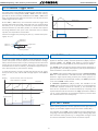
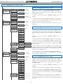
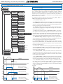
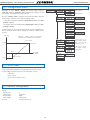
1.13 Funcon ‘Trigger Sense’
Special working mode for counter applicaons with high frequency
signals, up to 250 KHz. Applies only to the counter mode (‘cn.1’).
The acvaon of the ‘FAST’ mode congures the signal detecon by
rising edge. The rst edge detected, either rising or falling edge, aer
the instrument restart (power-up, or conguraon change) is used
for internal inializaon and will not be counted as impulse.
1.14 Funcon ‘cycle counter’ 1.15 ‘SLOW’ mode
The trigger level is automacally congured when selecng a sensor
from the ‘Sensor / Conguraon’ (‘SnSr’ / ‘Auto’) menu list. The trig-
ger level can be also manually modied from the ‘SnSr’ / ‘TrIG’ menu
entry. The selected value applies to channels ‘A’ and ‘B’ (the reset has
a xed trigger level at 2.5 Vdc).
At the ‘SnSr’ / ‘TrIG’ menu, the instrument shows the trigger level
and two vercal leds to the le. These leds inform in real me about
the status (‘0’ or ‘1’) of the input channels ‘A’ and ‘B’. When the led
switches between up and down posion, it indicates that impulses
are being detected at the input. If the instrument does not detect
impulses, the led posions remain xed.
Increase the trigger level pressing key ‘UP’ (5) and decrease press-
ing key ‘LE’ (3).
Vdc
Time
Trigger level
‘1’
‘0’
Signal detected
channel ‘A’
Status ‘1’
Trigger level
Status ‘0’
Leds of the ‘Trigger
Sense’ funcon
channel ‘B’
1.16 ‘FAST’ mode
Reading
Time
Setpoint 1
Impulse counter, with ‘reset to preset’
when setpoint 1 is reached
Preset
Time
Cycle counter
0
1
2
3
The counter modes allow to acvate a reset funcon (to ‘0’ or to
‘preset’ value) when an alarm setpoint is reached. With this congu-
raon, the instrument counts in cycles, counng from the instrument
preset value up to the alarm setpoint. Each cycle is counted and ac-
cumulated into an internal memory, accessible through the ‘fast ac-
cess’ menu (key UP (5) (see secon 1.19.12)).
To reset the memory of cycles, visualize the value at the ‘uP’ menu,
then press the (5) key and the ‘rSt’ message appears. Press (<) to
reset.

9
DPF20
Frequency, rate, total or period counter
Instruction Manual
The instrument has two menus accessible to the user :
‘Conguraon menu’ (key SQ) (<)
‘Fast access’ menu (key UP) (5)
Conguraon menu
The ‘conguraon menu’ modies the conguraon parameters to
adapt the instrument to the applicaon needs. To access the ‘con-
guraon menu’ press for 1 second the SQ (<) key. This access can
be blocked by acvang the ‘Password’ (‘PASS’) funcon. While
operang the ‘conguraon menu’, the alarm status is ‘hold’ to the
status they had before accessing the menu, and the output and con-
trol modules remain in ‘error’ state. When leaving the ‘conguraon
menu’, the instrument applies a system reset, followed by a brief
disconnecon of the alarms and the output and control modules.
Funconality is then recovered.
For a detailed explanaon on the ‘conguraon menu’ see secon
1.19, and for a full view of the ‘conguraon menu’ structure see
secon 1.20.
‘Fast access’ menu
The ‘fast access’ menu is an operator congurable menu, providing
fast and direct access to the most usual funcons of the instrument
with a single key pad stroke. Press key UP (5) to access this menu.
See secon 1.19.12 for a list of funcons eligible for ‘fast access’ in
this instrument. The ‘Password’ (‘PASS’) funcon does not block ac-
cess to this menu. Accessing and modifying parameters in the ‘fast
access’ menu does not interfere with the normal funconality of the
instrument, and it does not generate any system reset when validat-
ing the changes.
Front key pad descripon
Key SQ (<) - press the SQ (<) key for 1 second to access the ‘con-
guraon menu’. Inside the menu, the SQ (<) key funcons as a
‘ENTER’ key. It selects and accesses the menu opon currently dis-
played. At menus with numerical value entries, it validates the num-
ber displayed.
Key UP (5) - the UP (5) key gives access to the ‘fast access’ menu.
Inside the menus, it moves vercally through the dierent menu op-
ons. At menus with numerical value entries, it modies the digit
selected by increasing its value to 0, 1, 2, 3, 4, 5, 6, 7, 8, 9.
Key LE (3) - inside the menus, the LE (3) key funcons as the ‘ES-
CAPE’ key. It leaves the selected menu, and eventually, will leave the
whole menu. When leaving the ‘conguraon menu’ with the LE (3)
key, the changed parameters are acvated. At menus with numeri-
cal value entries, the LE (3) key allows to select the acve digit. To
modify the value of the selected digit use the UP (5) key.
Menu ‘rollback’
Aer 30 seconds without interacon from the operator, the instru-
ment will rollback and leave the ‘conguraon menu’ or the ‘fast ac-
cess’ menu. All changes will be discarded.
1.17 How to operate the menus
Messages and errors
‘Err.1’ incorrect password.
‘Err.2’ at ‘oPt.X’ menu entry. Installed module is not recognized.
‘Err.8’ excitaon voltage overload.
‘999999’ + ashing mode. Reading is in overrange.
‘-199999’ + ashing mode. Reading is in underrange.
Table 6 - Messages and error codes
The error messages are shown on display in ash mode.
Example of operaon inside the
‘conguraon menu’.
1. The SQ (<) key enters into the
‘conguraon menu’.
2. The SQ (<) key enters into the
‘Func’ opon menu.
3. The UP (5) key moves through
the menu opons.
4. The SQ (<) key selects the
desired range and returns to the
‘Func’ menu.
5. The LE (3) key leaves the ac-
tual menu level and moves to the
previous menu level.
6. The LE (3) key leaves the ‘con-
guraon menu’. Changes are ap-
plied and saved at this moment.
1.18 Messages and errors
Funcon mode
(2)
(3)
(3)
(3)
(3)
(3)
(4)
(4)
(4)
(4)
(5)
(5)
(5)
(5)
(3)
(3)
(6)
(6)
(1)

10
DPF20
Frequency, rate, total or period counter
Instruction Manual
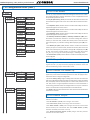
Decimal point
Press ‘SQ’ (<) for 1 second to access the ‘conguraon menu’.
For a descripon on how to operate inside the menus see secon
1.17. For a full vision of the ‘conguraon menu’ structure see
secon
1.20.
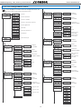
To congure the inial set up of the instrument, select the funcon
mode, the decimal point posion, scale the reading and congure
the mode selected and the sensor.
Enter the ‘Funcon mode’ (‘Func’) menu and select the desired func-
on, from the 5 counng modes, 2 ratemeter modes and the period-
meter mode available.
• ‘Counter’ (‘cn. 1’) - normal counter mode. Impulses input at chan-
nel A. Channel B disabled.
• ‘Counter quadrature’ (‘cnq.2’) - counter mode for quadrature sig-
nals. Impulses input at channel A and B, in quadrature.
• ‘Counter + inhibion’ (‘cnI.3’) - counter mode with inhibion con-
trol. Impulses input at channel A. Inhibion control on channel B.
• ‘Counter + control add / substract’ (‘cnc.4’) - counter mode with
control for add / substract. Impulses input at channel A. Control for
the add or substract funcon on channel B.
• ‘Counter dierenal’ (‘cnd.5’) - counter mode with dierenal
funcon. Impulses received at channel A add. Impulses received at
channel B substract.
• ‘Ratemeter’ (‘rt.6’) - ratemeter mode. Impulses input at channel
A. Channel B disabled.
• ‘Ratemeter quadrature’ (‘rtq.7’) - ratemeter mode for quadrature
signals. Impulses input at channel A and B, in quadrature.
• ‘Periodmeter’ (‘Prd.8’) - periodmeter mode. Impulses input at
channel A. Channel B disabled.
Access the ‘Decimal point’ (‘dP’) menu to select the decimal point
posion. Move the decimal point by pressing the ‘LE’ (3) key.
Congure the funcon mode selected (‘cnF.2’ to ‘cnF.8’). See sec-
ons 1.19.2 to 1.19.9.
Congure the sensor at the ‘SnSr’ menu. See secon 1.19.10.
Funcon
mode
Counter
Counter quadrature
Counter + inhibion
Counter + control add / substract
Counter dierenal
Ratemeter
Ratemeter quadrature
Periodmeter
Conguraon menu for mode ‘counter’ (‘cn.1’). Total impulses re-
ceived are mulplied by the value of the ‘mulplier’ (‘MuLt’) register
and divided by the ‘divider’ (‘dIV’) register. Result is refreshed on the
display.
• assign the value for parameter ‘Mulplier’ (‘MuLt’) from 1 to
999999.
• assign the value for parameter ‘Divider’ (‘dIV’) from 1 to 999999.
• assign the value for ‘Preset’ (‘PrSt’) from -199999 to 999999. Reset
acvaon loads on display the preset value.
• select the counng mode (‘ModE’) to ‘uP’ for upwards counng
(impulses received add) or ‘doWn’ for downwards counng (impuls-
es received substract).
• to acvate the ‘FAST’ mode (‘FASt’) select ‘on’. See secon 1.16 for
more informaon on the ‘FAST’ mode.
1.19.2 Conguraon for ‘cn.1’
The next menu accesses the conguraon parameters for the ‘funcon mode’ (‘Func’)
selected. Conguraon parameters are slightly dierent for each ‘funcon mode’. In
the next entries, all 7 possible conguraon menus are explained, ‘cnF.1’ to ‘cnF.7’, one
for each ‘funcon mode’.
Mulplier
1 to 999999
Divider
1 to 999999
Conguraon
counter
Mulplier
Divider
Preset
Preset value
-199999 to 999999
Mode
Up
Down
‘FAST’ mode
1.19 Conguraon menu
1.19.1 Inial set-up

11
DPF20
Frequency, rate, total or period counter
Instruction Manual
1.19 Conguraon menu (cont.)
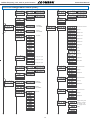
Conguraon menu for mode ‘counter quadrature’ (‘cnq.2’). To-
tal impulses received are mulplied by the value of the ‘mulplier’
(‘MuLt’) register and divided by the ‘divider’ (‘dIV’) register. Result is
refreshed on the display.
• assign the value for parameter ‘Mulplier’ (‘MuLt’) from 1 to
999999.
• assign the value for parameter ‘Divider’ (‘dIV’) from 1 to 999999.
• assign the value for ‘Preset’ (‘PrSt’) from -199999 to 999999. Reset
acvaon loads on display the preset value.
• select the ‘edges’ to count for each quadrature cycle (‘q.124’). Se-
lect ‘1--1’ for 1 impulse per quadrature cycle. Select ‘1--2’ for 2 im-
pulses per quadrature cycle. Select ‘1--4’ for 4 impulses per quadra-
ture cycle.
1.19.3 Conguraon for ‘cnq.2’
Conguraon menu for mode ‘counter + inhibion control’ (‘cnI.3’).
Total impulses received are mulplied by the value of the ‘mulplier’
(‘MuLt’) register and divided by the ‘divider’ (‘dIV’) register. Result is
refreshed on the display.
• assign the value for parameter ‘Mulplier’ (‘MuLt’) from 1 to
999999.
• assign the value for parameter ‘Divider’ (‘dIV’) from 1 to 999999.
• assign the value for ‘Preset’ (‘PrSt’) from -199999 to 999999. Reset
acvaon loads on display the preset value.
• select the counng mode (‘ModE’) to ‘uP’ for upwards counng
(impulses received add) or ‘doWn’ for downwards counng (impuls-
es received substract).
• select the acvaon mode for the ‘inhibion’ (‘Inh’) control. Select
‘on_h’ to inhibit the counng when channel B is at logical state ‘1’.
Select ‘on_0’ to inhibit the counng when channel B is at logical state
‘0’.
1.19.4 Conguraon for ‘cnI.3’
Conguraon menu for mode ‘counter + control add / substract’
(‘cnc.4’). Total impulses received are mulplied by the value of the
‘mulplier’ (‘MuLt’) register and divided by the ‘divider’ (‘dIV’) regis-
ter. Result is refreshed on the display.
• assign the value for parameter ‘Mulplier’ (‘MuLt’) from 1 to
999999.
• assign the value for parameter ‘Divider’ (‘dIV’) from 1 to 999999.
• assign the value for ‘Preset’ (‘PrSt’) from -199999 to 999999. Reset
acvaon loads on display the preset value.
• select the acvaon mode for the ‘control add / substract’ (‘Add’).
Select ‘on_h’ acvates the addion of impulses received on chan-
nel A when channel B is at logical state ‘1’ (impulses on channel A
substract if channel B is at logical state ‘0’). Select ‘on_0’ acvates
the addion of impulses received on channel A when channel B is
at logical state ‘0’ (impulses on channel A substract if channel B is at
logical state ‘1’).
1.19.5 Conguraon for ‘cnc.4’
Mulplier
1 to 999999
Divider
1 to 999999
Conf. counter
+ inhibion
Mulplier
Divider
Preset
Valor del preset
-199999 to 999999
Mode
Up
Down
Inhibion
Inhibits if chan-
nel B is high
Inhibits if chan-
nel B is 0 Vdc
Conf. counter
quadrature
Mulplier
1 to 999999
Divider
1 to 999999
Mulplier
Divider
Preset
Valor del preset
-199999 to 999999
Edges
1 imp. per cycle
2 imp. per cycle
4 imp. per cycle
Mulplier
1 to 999999
Divider
1 to 999999
Conguraon
counter +
control
add / substract
Mulplier
Divider
Preset
Valor del preset
-199999 to 999999
Control A/S
Adds if channel
B is high
Adds if channel
B is 0 Vdc

12
DPF20
Frequency, rate, total or period counter
Instruction Manual
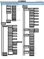
Conguraon menu for mode ‘counter dierenal’ (‘cnd.5’). To-
tal impulses received are mulplied by the value of the ‘mulplier’
(‘MuLt’) register and divided by the ‘divider’ (‘dIV’) register. Result is
refreshed on the display.
• assign the value for parameter ‘Mulplier’ (‘MuLt’) from 1 to
999999.
• assign the value for parameter ‘Divider’ (‘dIV’) from 1 to 999999.
• assign the value for ‘Preset’ (‘PrSt’) from -199999 to 999999. Reset
acvaon loads on display the preset value.
Impulses received on channel A add. Impulses received on channel
B substract.
1.19.6 Conguraon for ‘cnd.5’
Conguraon menu for mode ‘ratemeter’ (‘rt.6’). Frequency mea-
sured is mulplied by the value of the ‘mulplier’ (‘MuLt’) register
and divided by the ‘divider’ (‘dIV’) register. Result is refreshed on the
display. Measure is updated at the rate dened on the ‘GATE’ regis-
t e r.
• assign the value for parameter ‘Mulplier’ (‘MuLt’) from 1 to
999999.
• assign the value for parameter ‘Divider’ (‘dIV’) from 1 to 999999.
• select the value for the ‘Time window’ (‘GAtE’). Available values
are : 0.5, 1.0, 2.0, 4.0, 8.0 or 16.0 seconds. The me window denes
the display refresh me. This parameter has no eect if the ‘SLOW’
mode is acve.
• for slow frequencies acvate the ‘SLoW’ parameter conguring the
‘tIME’ parameter between 1 and 1000 seconds. Congure the ‘nuMb’
parameter between 1 and 32 impulses. See secon 1.15 for more in-
formaon on the ‘SLoW’ mode.
• in case of unstable signals, acvate the ‘average lter’ (‘AVr’) func-
on. It acvates a recursive lter on the reading. the lter is stronger
for higher values, from 0.0 to 99.9.
1.19.7 Conguraon for ‘rt.6’
1.19 Conguraon menu (cont.)
Conguraon menu for mode ‘ratemeter quadrature’ (‘rtq.7’).
Frequency measured is mulplied by the value of the ‘mulplier’
(‘MuLt’) register and divided by the ‘divider’ (‘dIV’) register. Result is
refreshed on the display. Measure is updated at the rate dened on
the ‘GATE’ register.
• assign the value for parameter ‘Mulplier’ (‘MuLt’) from 1 to
999999.
• assign the value for parameter ‘Divider’ (‘dIV’) from 1 to 999999.
• select the value for the ‘Time window’ (‘GAtE’). Available values
are : 0.5, 1.0, 2.0, 4.0, 8.0 or 16.0 seconds. The me window denes
the display refresh me. This parameter has no eect if the ‘SLOW’
mode is acve.
• select the ‘edges’ to count for each quadrature cycle (‘q.124’). Se-
lect ‘1--1’ for 1 impulse per quadrature cycle. Select ‘1--2’ for 2 im-
pulses per quadrature cycle. Select ‘1--4’ for 4 impulses per quadra-
ture cycle.
1.19.8 Conguraon for ‘rtq.7’
Mulplier
1 to 999999
Divider
1 to 999999
Conguraon
counter
dierenal
Mulplier
Divider
Preset
Preset value
-199999 to 999999
Edges
1 imp. per cycle
2 imp. per cycle
4 imp. per cycle
Mulplier
1 to 999999
Divider
1 to 999999
Seconds
Conf. ratemeter
quadrature
Mulplier
Divider
Time window
Mulplier
1 to 999999
Divider
1 to 999999
Seconds
Conf. ratemeter
Mulplier
Divider
Time window
‘SLOW’ mode
Average lter
Filter strength
(0 = disabled)
Max. waing me
Number of pulses

13
DPF20
Frequency, rate, total or period counter
Instruction Manual
1.19 Conguraon menu (cont.)
Conguraon menu for mode ‘periodmeter’ (‘Prd.8’). Period mea-
sured is mulplied by the value of the ‘mulplier’ (‘MuLt’) register
and divided by the ‘divider’ (‘dIV’) register. Result is refreshed on the
display. Measure is updated at the rate dened on the ‘GATE’ regis-
t e r.
• assign the value for parameter ‘Mulplier’ (‘MuLt’) from 1 to
999999.
• assign the value for parameter ‘Divider’ (‘dIV’) from 1 to 999999.
• select the value for the ‘Time window’ (‘GAtE’). Available values
are : 0.5, 1.0, 2.0, 4.0, 8.0 or 16.0 seconds. The me window denes
the display refresh me. This parameter has no eect if the ‘SLOW’
mode is acve.
• for long periods acvate the ‘SLoW’ parameter conguring the
‘tIME’ parameter between 1 and 1000 seconds. Congure the ‘nuMb’
parameter between 1 and 32 impulses. See secon 1.15 for more in-
formaon on the ‘SLoW’ mode.
• in case of unstable signals, acvate the ‘average lter’ (‘AVr’) func-
on. It acvates a recursive lter on the reading. the lter is stronger
for higher values, from 0.0 to 99.9.
1.19.9 Conguraon for ‘Prd.8’
• for slow frequencies acvate the ‘SLoW’ parameter conguring the
‘tIME’ parameter between 1 and 1000 seconds. Congure the ‘nuMb’
parameter between 1 and 32 impulses. See secon 1.15 for more in-
formaon on the ‘SLoW’ mode.
• in case of unstable signals, acvate the ‘average lter’ (‘AVr’) func-
on. It acvates a recursive lter on the reading. the lter is stronger
for higher values, from 0.0 to 99.9.
1.19.10 Sensor conguraon
The sensor conguraon menu (‘SnSr’) provides conguraon for
the input secon of the instrument, the excitaon voltage and the
trigger level, for accurate detecon of the impulses.
• ‘Automac conguraon’ (‘Auto’) - if a standard sensor is used,
select one of the sensors provided at the ‘Auto’ menu list. The instru-
ment will automacally congure the parameters according to Table
2 (see secon 1.8). If this conguraon does not detect impulses,
manually modify the values for the parameters indicated below.
Mulplier
1 to 999999
Divider
1 to 999999
Conf.
Periodmeter
Mulplier
Divider
Time window
Seconds
Sensor
NPN 2 wire
Mechanical contact
Namur
Automac conf.
NPN 3 wire
PNP 2 wire
PNP 3 wire
Push pull
TTL
CMOS
Pick-up
Inducve
Vac <30 V
‘SLOW’ mode
Average lter
Filter strength
(0 = disabled)
Max. waing me
Number of pulses
‘SLOW’ mode
Average lter
Filter strength
(0 = disabled)
Max. waing me
Number of pulses

14
DPF20
Frequency, rate, total or period counter
Instruction Manual
• ‘Pulls on channel A’ (‘PuL.A’) - acvates pull resistors at chan-
nel A. Select ‘P.uP’ to acvate pull-up resistors (needed for NPN
sensors). Select ‘P.dn’ to acvate pull-down resistors (needed PNP
sensors). Pull-up and pull-down selecon congure the trigger level
to 2,5 Vdc.
• ‘Pulls on channel B’ (‘PuL.b’) - see previous menu entry ‘Pulls on
channel A’.
• ‘Pulls on reset’ (‘PuL.r’) - see previous menu entry ‘Pulls on channel
A’. Trigger level for reset channel is xed to 2,5 Vdc.
• ‘trigger level’ (‘trIG’) - input signal value in Vdc at which the in-
strument detects impulse. Selectable between 0,0 and 3,9 Vdc. Trig-
ger level is the same for channels A and B. Trigger level for reset
channel is xed at 2,5 Vdc. The two leds at the le of the trigger
level are part of the ‘Trigger Sense’ ulity for easy locaon of the
proper trigger level (see secon 1.13).
• ‘Acvaon for channel A’ (‘Act.A’) - congures the acvaon of
channel A by rising edge (‘on_h’) or by falling edge (‘on_0’)
• ‘Acvaon for reset channel’ (‘Act.r’) - congures the acva-
on of the reset channel by rising edge (‘on_h’) or by falling edge
(‘on_0’)
• ‘Excitaon voltage’ (‘V.EXc’) - congures the value of the excita-
on voltage at 5 Vdc, 9 Vdc, 15 Vdc and 18 Vdc. Select ‘no’ to disable
the excitaon voltage.
• ‘Anrrebound lter’ (‘rbnd’) - the anrrebound lter blocks ad-
dional rebounds (typically from a mechanical contact sensor) from
the same single impulse, prevenng that a single impulse counts
for more than 1. Value between 0 mSeconds and 1000 mSeconds.
When an impulse is received, impulse detecon is disabled for the
duraon of the me congured in this parameter. Aer me has
passed, impulse detecon is enabled again. Recommended value
for a mechanical contact : 100 mSeconds.
1.19 Conguraon menu (cont.)
Anrrebound
by rising edge
by falling edge
Acvaon for
channel A
by rising edge
by falling edge
Acvaon for
reset
Excitaon voltage
Trigger level
Trigger level (from
0.0 Vdc a 3.9 Vdc).
See secon 1.15
for ‘Trigger Sense’
ulity
Anrrebound lter
(0 to 1000 mSec.)
Pull-down
No pull resistor
Pull-up
Pulls on reset
Pulls on channel B
Pull-down
No pull resistor
Pull-up
Pull-down
No pull resistor
Pull-up
Pulls on channel A

15
DPF20
Frequency, rate, total or period counter
Instruction Manual
1.19 Conguraon menu (cont.)
The ‘Alarms’ (‘ALr’) menu congures the independent acvaon of
up to 3 relay outputs (or transistor or SSR drive control), installed
with the R1 oponal modules (or T1 or SSR) (see secon 2.1). For
outputs up to 4 and 6 relays, see special modules R2, R4 and R6 at
secon 2.6. The alarm states are indicated in the front display with
leds marked as ‘1’, ‘2’ and ‘3’.
To congure an alarm, enter into the alarm menu (‘ALr1’, ‘ALr2’ or
‘ALr3’) and congure the following parameters :
• select ‘Acve’ (‘Act’) to ‘on’
• at ‘Alarm type’ (‘TypE’) select the alarm to act as a maximum type
alarm (‘MAX’) or a minimum type alarm (‘MIn’). The maximum type
alarm (or minimum type alarm) acvates when the display value is
higher (or lower) than the setpoint value.
• at ‘Setpoint’ (‘SEt’) enter the value for the alarm acvaon point.
This parameter is eligible for conguraon through the ‘Fast access’
menu (see secon 1.19.12).
• congure the hysteresis value at ‘Hysteresis’ (‘hySt’). The hyster-
esis applies to the deacvaon process of the alarm. The alarm de-
acvates when the reading has passed the setpoint value plus the
hysteresis value. Hysteresis helps to avoid repeve switching of the
alarm relays, due to uctuang input signals around the setpoint.
• at ‘Acvaon delay’ (‘dEL.0’) congure the delay to apply before
alarm acvaon. The acvaon delay starts counng when the set-
point value is passed. Value from 0.0 to 99.9 seconds.
• at ‘Deacvaon delay’ (‘dEL.1’) congure the delay to apply
before alarm deacvaon. The deacvaon delay starts counng
when the setpoint value plus the hysteresis value, is passed. Value
from 0.0 to 99.9 seconds.
• to work with ‘windowed alarms’ (see graphical example below)
acvate ‘Setpoint 2’ (‘SEt2’) to ‘on’ and then congure the desired
second setpoint value. Second setpoint must always be higher in
value than the rst setpoint.
• the ‘Relay inverted’ (‘r.Inv’) parameter inverts the normal relay
connecons. When set to ‘on’ the relay will be acve when alarm is
inacve. For security applicaons where an inacve relay controls
the shutdown of the system.
• the ‘Locked alarm’ (‘A.Lck’) parameter disables the automac
deacvaon of the alarm. Alarm deacvaon must be performed
manually, by pressing the ‘LE’ front buon (see secon 1.19.14)
• the ‘On alarm’ (‘on.AL’) parameter assigns a predened behav-
iour when alarm is acvated. Select ‘cont’ to connue counng.
Select ‘to_0’ to load ‘0’ on displays. Select ‘to_p’ to load preset
value on display. Parameter ‘dEL.1’ is set to 1 second when ‘to_0’
or ‘to_p’ are selected.
1.19.11 Alarms
On alarm
Connue
To zero
To preset
Alarm 1
Setpoint
Hysteresis
Setpoint 2
Acve
Alarm type
Alarms
Acvaon delay
Deacvaon delay
Relay inverted
Locked alarm
Reading
Time
setpoint
hysteresis
Alarm as maximum,
no hysteresis, no delays
on
o
Time
acvaon
delay
on
o
deacvaon
delay
Time
Alarm as maximum,
with hysteresis and delays
on
o
Time
Alarm as minimum,
no hysteresis, no delays
Reading
Time
Setpoint 2
Setpoint 1
Alarm as minimum,
with double setpoint,
no hysteresis, no delays
on
o
Time

16
DPF20
Frequency, rate, total or period counter
Instruction Manual
1.19 Conguraon menu (cont.)
The ‘On Power Up’ (‘on.Pu’) menu congures funcons to apply at start-up. It
applies only to instrument restart aer power loss. It does not apply to instru-
ment restart due to change in conguraon.
• parameter ‘Delay’ (‘dLAy’) assigns a waing me in seconds. The instrument
waits the congured me before starng normal funcon. During this waing
me, the display shows all decimal points on in ash mode, all alarms are in
‘oFF’ state, there is no signal acquision and there is no communicaons or
control being performed. Aer the congured me is over, the instrument
starts in normal funcon. Delay value between 0 and 200 seconds.
• the ‘Reset’ (‘rSt’) parameter will execute a reset of the counter each me the
instrument is restarted.
1.19.15 Menu ‘On Power Up’
Tools
Key UP
(‘fast access’)
Memory of
maximum
Memory of
minimum
Setpoint 1
Setpoint 2
Setpoint 3
Memory of
cycles
Preset value
On power-up
Delay Seconds
Reset
The ‘UP’ (5) key at the front of the instrument gives access to a list of func-
ons congurable by the operator. See secon 1.17 for an explanaon on how
to operate the ‘fast access’ menu.
The ‘Key UP (Fast access)’ (‘K.uP’) menu allows to select which funcons will
be accessible through the ‘fast access’ menu. Select ‘on’ to acvate each func-
on.
• the ‘Setpoint
1’ (‘ALr1’) funcon allows to visualize and modify the alarm 1
setpoint through the ‘fast access’ menu.
• the ‘Setpoint
2’ (‘ALr2’) funcon allows to visualize and modify the alarm 2
setpoint through the ‘fast access’ menu.
• the ‘Setpoint
3’ (‘ALr3’) funcon allows to visualize and modify the alarm 3
setpoint through the ‘fast access’ menu.
• the ‘Memory of maximum’ (‘MAX’) or ‘Memory of minimum’ (‘MIn’) func-
ons allow to visualize the maximum or minimum reading value stored in
memory. To reset this value, visualize the memory value at the ‘fast access’
menu with key UP (5) and when message ‘rSt’ is displayed, press (<) to re-
set.
• the ‘Memory of cycles’ (‘cYcL’) funcon allow to visualize and reset the
memory of cycles. To reset this value, visualize the memory value at the ‘fast
access’ menu with key UP (5) and when message ‘rSt’ is displayed, press (<)
to reset. The memory of cycles countes ‘+1’ each me a reset alarm occurs
(‘on_AL’ / ‘to_0’ or ‘to_P’) or a reset by ‘overrange’ / ‘underrange’ occurs.
• the ‘Preset value’ (‘PrSt’) funcon allows to visualize and modify the preset
value congured.
1.19.12 Fast access
If only a single funcon is selected for the ‘fast access’ menu, press-
ing the the ‘UP’ (5) key will shortly display the funcon name and
then automacally jump to the funcon value.
1.19.13 Super fast access
The ‘LE’ (3) key at the front of the instrument can be congured to
acvate a funcon.
• the ‘No funcon’ (‘nonE’) value assigns no funcon.
• the ‘Front reset’ (‘F.rSt’) value asigns the reset funon.
• the ‘Alarm unlock’ (‘A.Lck’) value assigns the manual unlock of the
alarms funcon, for instruments with the ‘Locked alarms’ (‘A.Lck’)
funcon acvated (see secon 1.19.11)
• the ‘Reset and alarm unlock’ (‘Fr.AL’) assigns the two previous
funcons to the same buon.
1.19.14 Menu ‘Key LE’
Key LE
Front reset
Alarm unlock
No funcon
Reset and alarm unlock

17
DPF20
Frequency, rate, total or period counter
Instruction Manual
At the ‘Password’ (‘PASS’) menu select a 6 digit code to block access
to the ‘conguraon menu’. Instrument conguraon will not be ac-
cessible to non authorized personnel. To acvate the ‘Password’ se-
lect ‘on’ and introduce the code.
The code will be requested when trying to access the ‘conguraon
menu’ (key ‘SQ’ (<)). The ‘fast access’ menu is not password pro-
tected.
The ‘Version’ (‘VEr’) menu informs of the current rmware version
installed in the module.
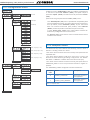
1.19.16 Menus ‘Overrange / underrange’
At the ‘Brightness’ (‘LIGh’) menu select the light intensity for the
front leds. With this funcon it is possible to adapt the instrument to
the environment light intensity.
1.19.18 Vexc. control
Menus ‘OPt.1’, ‘OPt.2’ and ‘OPt.3’ give access to the ‘conguraon
menus’ of the output and control modules installed at slots Opt.1,
Opt.2 and Opt.3.
See secon 2 for a list of output and control modules available for
each slot. The ‘conguraon menu’ of each module is described at
the User’s Manual of each module.
1.19.19 Funcon ‘Password’
At the ‘Factory reset’ (‘FAct’) menu, select ‘yes’ to load the default
factory conguraon for the instrument (see secon 1.21).
1.19.20 Factory reset
1.19.21 Firmware version
The ‘Counter overrange’ (‘c.orG’) and ‘Counter underrange’ (‘c.urG’)
parameters congure the behavior of the instrument when reading
is higher than ‘9999’ (overrange) or lower than ‘-1999’ (underrange).
Select ‘FLSH’ to enter reading into ash mode. Select ‘to_0’ to apply
a reset to ‘0’. Select ‘to_P’ to apply a reset to preset value.
1.19.22 Brightness
1.19.17 Le zeros
The ‘Le zeros’ (‘L.ZEr’) parameter controls the le zeros on or o.
1.19 Conguraon menu (cont.)
Password
Version
Factory reset
Minimum
Brightness
Maximum
Standard
Opon
1
Conguraon menu for the module installed at Opt.1
Opon
2
Conguraon menu for the module installed at Opt.2
Opon 3
Conguraon menu for the module installed at Opt.3
Counter
overrange
Flash
To zero
To preset
Counter
underrange
Flash
To zero
To preset
Le zeros
With le zeros
Without le zeros
Vexc. control
with Vexc. error control
without Vexc. error control
1.19.23 Access to oponal modules
The ‘Vexc control’ (‘V.ctr’) parameters enables the ‘Err.8’ message,
when consumpon requested to the excitaon voltage is higher than
the current the instrument can provide.

18
DPF20
Frequency, rate, total or period counter
Instruction Manual
Select with key LE
Decimal point
Press ‘SQ’ (<) for 1 second to access the ‘Conguraon menu’. See
secon
1.19 for a descripon of each menu entry.
Funcon
mode
Mulplier
1 to 999999
Divider
1 to 999999
Conguraon
counter
Mulplier
Divider
Preset
Preset value
-199999 to 999999
Mode
Up
Down
‘FAST’ mode
Conf. counter
quadrature
Mulplier
1 to 999999
Divider
1 to 999999
Mulplier
Divider
Preset
Preset value
-199999 to 999999
Edges
1 imp. per cycle
2 imp. per cycle
4 imp. per cycle
Mulplier
1 to 999999
Divider
1 to 999999
Conf. counter
+ inhibion
Mulplier
Divider
Preset
Preset value
-199999 to 999999
Mode
Up
Down
Inhibion
Inhibits if chan-
nel B is high
Inhibits if chan-
nel B is 0 Vdc
Mulplier
1 to 999999
Divider
1 to 999999
Conguraon
counter +
control
add / substract
Mulplier
Divider
Preset
Preset value
-199999 to 999999
Control A/S
Adds if channel
B is high
Adds if channel
B is 0 Vdc
Mulplier
1 to 999999
Divider
1 to 999999
Conguraon
counter
dierenal
Mulplier
Divider
Preset
Preset value
-1999 to 999999
Mulplier
1 to 999999
Divider
1 to 999999
Seconds
Conf. ratemeter
Mulplier
Divider
Time window
1.20 Full conguraon menu
Counter
Counter quadrature
Counter + inhibion
Counter + control add / substract
Counter dierenal
Ratemeter
Ratemeter quadrature
Periodmeter

19
DPF20
Frequency, rate, total or period counter
Instruction Manual
Mulplier
1 to 999999
Divider
1 to 999999
Seconds
Conf. ratemeter
quadrature
Mulplier
Divider
Time window
Mulplier
1 to 999999
Divider
1 to 999999
Conf. ratemeter
Mulplier
Divider
Time window
Seconds
Edges
1 imp. per cycle
2 imp. per cycle
4 imp. per cycle
1.20 Full conguraon menu (cont.)
Sensor
Automac conf.
Trigger level
Trigger level (from
0.0 Vdc a 3.9 Vdc).
See secon 1.15
for ‘Trigger Sense’
ulity
Pull-down
No pull resistor
Pull-up
Pulls on reset
Pulls on channel B
Pull-down
No pull resistor
Pull-up
Pull-down
No pull resistor
Pull-up
Pulls on channel A
NPN 2 wire
Mechanical contact
Namur
NPN 3 wire
PNP 2 wire
PNP 3 wire
Push pull
TTL
CMOS
Pick-up
Inducve
Vac <30 V
‘SLOW’ mode
Average lter
Filter strength
(0 = disabled)
Max. waing me
Number of pulses
‘SLOW’ mode
Average lter
Filter strength
(0 = disabled)
Max. waing me
Number of pulses
‘SLOW’ mode
Average lter
Filter strength
(0 = disabled)
Max. waing me
Number of pulses

20
DPF20
Frequency, rate, total or period counter
Instruction Manual
On alarm
Connue
To zero
To preset
Alarm 1
Setpoint
Hysteresis
Setpoint 2
Acve
Alarm type
Alarms
Acvaon delay
Deacvaon delay
Relay inverted
Locked alarm
Tools
Key UP
(‘fast access’)
Memory of
maximum
Memory of
minimum
Setpoint 1
Setpoint 2
Setpoint 3
Memory of
cycles
Preset value
On power-up
Delay Seconds
Reset
Key LE
Front reset
Alarm unlock
No funcon
Counter
overrange
Flash
To zero
To preset
Counter
underrange
Flash
To zero
To preset
1.20 Full conguraon menu (cont.)
Reset and alarm unlock
by rising edge
by falling edge
Acvaon for
reset
Excitaon voltage
Anrrebound
Anrrebound lter
(0 to 1000 mSec.)
rising edge
falling edge
Channel A ac-
vaon
Page is loading ...
Page is loading ...
Page is loading ...
Page is loading ...
Page is loading ...
Page is loading ...
Page is loading ...
Page is loading ...
Page is loading ...
Page is loading ...
Page is loading ...
Page is loading ...
Page is loading ...
Page is loading ...
Page is loading ...
Page is loading ...
Page is loading ...
Page is loading ...
Page is loading ...
Page is loading ...
-
 1
1
-
 2
2
-
 3
3
-
 4
4
-
 5
5
-
 6
6
-
 7
7
-
 8
8
-
 9
9
-
 10
10
-
 11
11
-
 12
12
-
 13
13
-
 14
14
-
 15
15
-
 16
16
-
 17
17
-
 18
18
-
 19
19
-
 20
20
-
 21
21
-
 22
22
-
 23
23
-
 24
24
-
 25
25
-
 26
26
-
 27
27
-
 28
28
-
 29
29
-
 30
30
-
 31
31
-
 32
32
-
 33
33
-
 34
34
-
 35
35
-
 36
36
-
 37
37
-
 38
38
-
 39
39
-
 40
40


Ask a question and I''ll find the answer in the document
Finding information in a document is now easier with AI
Related papers
-
Omega TXDIN1600S Owner's manual
-
-
-
-
-
-
-
-
-
Other documents
-
 AND AD-4531B User manual
-
 Camfil 4304004 FastFrame Owner's manual
-
 Magnetek IMPULSE G+/VG+ Series 4 Modbus RTU Drive Communication Owner's manual
-
 Simex STI-73 User manual
-
 Axel MC726 Series Quick start guide
-
Acrel 259 User manual
-
red lion GEMINI 2000 User manual
-
 Yokota YZ-T600A Owner's manual
-
 Ditel KOS1600F Technical Manual
-
Pulsar Imp 10 User manual


