Miller JC629243 Owner's manual
- Category
- Welding System
- Type
- Owner's manual
This manual is also suitable for

March
1982
FORM:
OM-1038E
Effective
With
Serial
No.
JC629243
MODEL
MILLERMATIC
70A
OWN
E
RS
MANUAL
HilliER
MILLER
ELECTRIC
MFG.
CO.
7185.
BOUNDS
ST.
P.O.
Box
1079
APPLETON.WI
54912
USA
ADDITIONAL
COPY
PRICE
70
CENTS
NWSA
CODE
NO.
4579
PRINTED
IN
U.S.A.

LIMITED
WARRANTY
EFFECTIVE:
JUNE
1,
1979
This
warranty
supersedes
all
previous
MILLER
warranties
and
is
ex
clusive
with
no
other
guarantees
or
warranties
expressed
or
implied.
LIMITED
WARRANTY-Subject
to
the
terms
and
conditions
As
a
matter
of
general
policy
only,
Miller
may
honor
claims
hereof,
Miller
Electric
Mfg.
Co.,
Appleton,
Wisconsin
warrants
submitted
by
the
original
user
within
the
foregoing
periods.
to
its
Distributor/Dealer
that
all
new
and
unused
Equipment
(I
furnished
by
Miller
is
free
from
defect
in
workmanship
and
In
the
case
of
Millers
breach
of
warranty
or
any
other
duty
material
as
of
the
time
and
place
of
delivery
by
Miller.
No
war-
with
respect
to
the
quality
of
any
goods,
the
exclusive
remedies
ranty
is
made
by
Miller
with
respect
to
engines,
trade
ac-
therefore
shall
be,
at
Millers
option
(II
repair
or
(2)
replacement
cessories
or
other
items
manufactured
by
others.
Such
or,
where
authorized
in
writing
by
Miller
in
appropriate
cases,
(3)
engines,
trade
accessories
and
other
items
are
sold
subject
to
the
reasonable
cost
of
repair
or
replacement
at
an
authorized
the
warranties
of
their
respective
manufacturers,
if
any
.
All
Miller
service
station
or
(4)
payment
of
or
credit for
the
purchase
engines
are
warranted
by
their
manufacturer
for
one
year
from
price
(less
reasonable
depreciation
based
upon
actual
use)
upon
date
of
original
purchase.
return
of
the
goods
at
Customers
risk
and
expense.
Upon
receipt
of
notice
of
apparent
defect
or
failure,
Miller
shall
instruct
the
clai-
Except
as
specified
below,
Millers
warranty
does
not
apply
mant
on
the
warranty
claim
procedures
to
be
followed.
to
components
having
normal
useful
life
of
less
than
one
Ill
year,
such
as
spot
welder
tips,
relay
and
contactor
points,
ANY
EXPRESS
WARRANTY
NOT
PROVIDED
HEREIN
AND
MILLERMATIC
parts
that
come
in
contact
with
the
welding
ANY
IMPLIED
WARRANTY,
GUARANTY
OR
REPRESENTA-
?
wire
including
nozzles
and
nozzle
insulators
where
failure
does
lION
AS
TO
PERFORMANCE,
AND
ANY
REMEDY
FOR
not
result
from
defect
in
workmanship
or
material.
BREACH
OF
CONTRACT
WHICH,
BUT
FOR
THIS
PROVISION,
k~
MIGHT
ARISE
BY
IMPLICATION,
OPERATION
OF
LAW,
Miller
shall
be
required
to
honor
warranty
claims
on
war-
CUSTOM
OF
TRADE
OR
COURSE
OF
DEALING,
INCLUDING
ranted
Equipment
in
the
event
of
failure
resulting
from
a
defect
ANY
IMPLIED
WARRANTY
OF
MERCHANTABILITY
OR
OF
within
the
following
periods
from
the
date
of
delivery
of
Equip-
FITNESS
FOR
PARTICULAR
PURPOSE,
WITH
RESPECT
TO
ment
to
the
original
user:
ANY
AND
ALL
EQUIPMENT
FURNISHED
BY
MILLER
IS
EX
CLUDED
AND
DISCLAIMED
BY
MILLER.
1.
Arc
welders,
power
sources
and
components
. .
1
year
2.
Original
main
power
rectifiers
3
years
EXCEPT
AS
EXPRESSLY
PROVIDED
BY
MILLER
IN
(labor
-
1
year
only)
WRITING,
MILLER
PRODUCTS
ARE
INTENDED
FOR
3.
All
welding
guns
and
feeder/guns
90
days
ULTIMATE
PURCHASE
BY
COMMERCIAL/INDUSTRIAL
4.
All
other
Millermatic
Feeders
1
year
USERS
AND
FOR
OPERATION
BY
PERSONS
TRAINED
AND
5.
Replacement
or
repair
parts,
exclusive
of
labor
.
60
days
EXPERIENCED
IN
THE
USE
AND
MAINTENANCE
OF
6.
Batteries
6
months
WELDING
EQUIPMENT
AND
NOT
FOR
CONSUMERS
OR
CONSUMER
USE.
MILLER
WARRANTIES
DO
NOT
EXTEND
provided
that
Miller
is
notified
in
writing
within
thirty
1301
days
TO,
AND
NO
RESELLER
IS
AUTHORIZED
TO
EXTEND
?
of
the
date
of
such
failure
MILLERS
WARRANTIES
TO,
ANY
CONSUMER.
.~
~
~,.
.
.
.
.~
j~

ERRATA
SHEET
Replaced
With
Quantity
Deleted
(Eff
w/JD703429)
+087
260
VALVE,
2.way
1/4
IPS
port
1/8
orifice
.
**First
digit
represents
page
no.-
digits
following
dash
represents
item
no
+
Optional
Parts
BE
SURE.TO
PROVIDE
MODEL
AND
SERIAL
NUMBER
WHEN
ORDERING
REPLACEMENT
PARTS.
Sept.
6,1983
FORM:
OM-1038E
After
this
manual
was
printed,
refinements
in
equipment
design
occurred.
This
sheet
lists
exceptions
to
data
appearing
later
in
this
manual.
AMENDMENT
TO
SECTION
7
-
TROUBLESHOOTING
Amend
Figure
7
-
1.
Circuit
Diagram
For
70A
Model
SiLVER
~~Q2
SCR
LJNIJIJNCTION
LEAD
END
VIEW
Circuit
Diagram
No.
B~O91
931
Figure
7
-
1.
Circuit
Diagram
For
70A
Model
Effective
With
Serial
No.
J0703429
And
Following
Dia.
**
Mkgs.
5-15
VR1
Part
No.
082
722
Description


TABLE
OF
CONTENTS
Section
No.
Page
No.
SECTION
1
-
SAFETY
RULES
FOR
OPERATION
OF
ARC
WELDING
POWER
SOURCE
1
-
1.
Introduction
1
1
-
2.
General
Precautions
1
1
-
3.
Arc
Welding
5
1
-
4.
Standards
Booklet
Index
6
SECTION
2
-
INTRODUCTION
2
-
1.
General
Information
And
Safety
7
2
-
2.
Receiving-Handling
7
2
3.
Description
7
SECTION
3
-
INSTALLATION
3-1.
Location
7
3
-
2.
Drive
Motor
7
3
-
3.
Contactor
Control
Connections
8
3
-
4.
Shielding
Gas
&
Weld
Cable
Installation
8
3
-
5.
Wire
Guide
&
Drive
Roll
Installation
8
3
-
6.
Eight
Inch
Spool
Type
Welding
Wire
Installation
9
3
-
7.
Four
Inch
Spool
Type
Welding
Wire
Installation
9
3
-
8.
Hub
Tension
Adjustment
9
3
-
9.
115
Volts
AC
Connection
9
SECTION
4
-
FUNCTION
OF
CONTROLS
4
-
1.
Power
Switch
10
4
-
2.
Wire
Speed
Control
10
4-3.
PurgeButton
10
4
-
4.
Inch
Switch
10
4
-
5.
Circuit
Breaker
10
SECTION
5
-
SEQUENCE
OF
OPERATION
5
-
1.
Welding
Wire
Threading
10
5
-
2.
Gas
Metal-Arc
Welding
11
5
-
3.
Shutting
Down
1
1
SECTION
6
-
MAINTENANCE
6-
1.
InspectionAnd
Upkeep
11
6
-
2.
Cleaning
Of
Drive
Rolls
12
SECTION
7
-
TROUBLESHOOTING
7-1.
General
12
7
-
2.
Troubleshooting
Chart
12


SECTION
1
-
SAFETY
RULES
FOR
OPERATION
OF
ARC
WELDING
POWER
SOURCE.
1-1.
INTRODUCTION
.
We
learn
by
experience.
Learning
safety
through
personal
experience,
like
a
child
touching
a
hot
stove
is
harmful,
wasteful,
and
un
wise.
Let
the
experience
of
others
teach
you.
Safe
practices
developed
from
experience
in
the
use
of
welding
and
cutting
are
described
in
this
manual.
Research,
development,
and
field
experience
have
evolved
reliable
equipment
and
safe
installation,
opera
tion,
and
servicing
practices.
Accidents
occur
when
equipment
is
improperly
used
or
maintained.
The
reason
for
the
safe
practices
may
not
always
be
given.
Some
are
based
on
common
sense,
others
may
require
technical
volumes
to
explain.
It
is
wiser
to
follow
the
rules.
Read
and
understand
these
safe
practices
before
at
tempting
to
install,
operate,
or
service
the
equipment.
Comply
with
these
procedures
as
applicable
to
the
par
ticular
equipment
used
and
their
instruction
manuals,
for
personal
safety
and
for
the
safety
of
others.
Failure
to
observe
these
safe
practices
may
cause
serious
injury
or
death.
When
safety
becomes
a
habit,
the
equipment
can
be
used
with confidence.
These
safe
practices
are
divided
into
two
Sections:
1
-
General
Precautions,
common
to
arc
welding
and
cutting;
and
2
-
Arc
Welding
(and
Cutting)
(only).
Reference
standards:
Published
Standards
on
safety
are
also
available
for
additional
and
more
complete
pro
cedures
than
those
given
in
this
manual.
They
are
listed
in
the
Standards
Index
in
this
manual.
ANSI
Z49.1
is
the
most
complete.
The
National
Electrical
Code,
Occupational
Safety
and
Health
Administration,
local
industrial
codes,
and
local
inspection
requirements
also
provide
a
basis
for
equip
ment
installation,
use,
and
service.
1-2.
GENERAL
PRECAUTIONS
A.
Burn
PreventIon
Wear
protective
clothing
-
leather
(or
asbestos)
gauntlet
gloves,
hat,
and
high
safety-toe
shoes.
Button
shirt
collar
and
pocket
flaps,
and
wear
cuff
less
trousers
to
avoid
entry
of
sparks
and
slag.
Wear
helmet
with
safety
goggles
or
glasses
with
side
shields
underneath,
appropriate
filter
lenses
or
plates
(protected
by
clear
cover
glass).
This
is
a
MUST
for
welding
or
cutting,
(and
chipping)
to
protect
the
eyes
from
radiant
energy
and
flying
metal.
Replace
cover
glass
when
broken,
pitted,
or
spattered.
See
1
-3A.2.
Avoid
oily
or
greasy
clothing.
A
spark
may
ignite
them.
Hot
metal
such
as
electrode
stubs
and
workpieces
should
never
be
handled
without
gloves.
Medical
first
aid
and
eye
treatment.
First
aid
facilities
and
a
qualified
first
aid
person
should
be
available
for
each
shift
unless
medical
facilities
are
close
by
for
im
mediate
treatment
of
flash
burns
of
the
eyes
and
skin
burns.
Ear
plugs
should
be
worn
when
working
on
overhead
or
in
a
confined
space.
A
hard
hat
should
be
worn
when
others
work
overhead.
Flammable
hair
preparations
should
not
be
used
by
per
Sons
intending
to
weld
or
cut.
B.
Toxic
Fume
Prevention
Adequate
ventilation.
Severe
discomfort,
illness
or
death
can
result
from
fumes,
vapors,
heat,
or
oxygen
enrichment
or
depletion
that
welding
(or
cutting)
may
produce.
Prevent
them
with
adequate
ventilation
as
described
in
ANSI
Standard
Z49.1
listed
1
in
Standards
index.
NEVER
ventilate
with
oxygen.
Lead
-,
cadmium
-,
zinc
-,
mercury
-,
and
beryllium
-
bearing
and
similar
materials,
when
welded
(or
cut)
may
produce
harmful
concentrations
of
toxic
fumes.
Ade
quate
local
exhaust
ventilation
must
be
used,
or
each
person
in
the
area
as
well
as
the
operator
must
wear
an
air-supplied
respirator.
For
beryllium,
both
must
be
us-
Metals
coated
with
or
containing
materials
that
emit
toxic
fumes
should
not
be
heated
unless
coating
is
removed
from
the
work
surface,
the
area
is
well
ven
tilated,
or
the
operator
wears
an
air-supplied
respirator.
Work
in
a
confined
space
only
while
it
is
being
ven
tilated
and,
if
necessary,
while
wearing
an
air-supplied
respirator.
Gas
leaks
in
a
confined
space
should
be
avoided.
Leaked
gas
in
large
quantities
can
change
oxygen
con
centration
dangerously.
Do
not
bring
gas
cyllinders
into
a
confined
space.
Leaving
confined
space,
shut
OFF
gas
supply
at
source
to
prevent
possible
accumulation
of
gases
in
the
space
if
downstream
valves
have
been
accidently
opened
or
left
open.
Check
to
be
sure
that
the
space
is
safe
before
re-entering
it.
Vapors
from
chlorinated
solvents
can
be
decomposed
by
the
heat
of
the
arc
(or
flame)
to
form
PHOSGENE,
a
highly
toxic
gas,
and
other
lung
and
eye
irritating
pro
ducts.
The
ultraviolet
(radiant)
energy
of
the
arc
can
also
decompose
trichloroethylene
and
per
chloroethylene
vapors
to
form
phosgene.
DO
NOT
WELD
or
cut
where
solvent
vapors
can
be
drawn
into
the
welding
or
cutting
atmosphere
or
where
the
radiant
energy
can
penetrate
to
atmospheres
containing
even
minute
amounts
of
trichioroethylene
or
per
chioroethylene.
ed.
OM-lO38Pagel

C.
Fire
end
Explosion
Prevention
Causes
of
fire
and
explosion
are:
combustibles
reached
by
the
arc,
flame,
flying
sparks,
hot
slag
or
heated
material;
misuse
of
compressed
gases
and
cylinders;
and
short
circuits.
BE
AWARE
THAT
flying
sparks
or
falling
slag
can
pass
through
cracks,
along
pipes,
through
windows
or
doors,
and
through
wall
or
floor
openings,
out
of
sight
of
the
goggled
operator.
Sparks
and
slag
can
fly
35
feet.
To
prevent
fires
and
explosion:
Keep
equipment
clean
and
operable,
free
of
oil,
grease,
and
(in
electrical
parts)
of
metallic
particles
that
can
cause
short
circuits.
if
combustibles
are
in
area,
do
NOT
weld
or
cut.
Move
the
work
if
practicable,
to
an
area
free
of
combustibles.
Avoid
paint
spray
rooms,
dip
tanks,
storage
areas,
yen
tilators.
If
the
work
cannot
be
moved,
move
com
bustibles
at
least
35
feet
away
out
of
reach
of
sparks
and
heat;
or
protect
against
ignition
with
suitable
and
snug-fitting,
fire-resistant
covers
or
shields.
Walls
touching
combustibles
on
opposite
sides
should
not
be
welded
on
(or
cut).Walls,
ceilings,
and
floor
near
work
should
be
protected
by
heat-resistant
covers
or
shields.
Fire
watcher
must
be
standing
by
with
suitable
fire
ex
tinguishing
equipment
during
and
for
some
time
after
welding
or
cutting
if:
a.
appreciable
combustibles
(including
building
construction)
are
within
35
feet
b.
appreciable
combustibles
are
further
than
35
feet
but
can
be
ignited
by
sparks
c.
openings
(concealed
or
visible)
in
floors
or
walls
within
35
feet
may
expose
com
bustibles
to
sparks
d.
combustibles
adjacent
to
walls,
ceilings,
roofs,
or
metal
partitions
can
be
ignited
by
radiant
or
conducted
heat.
Hot
work
permit
should
be
obtained
before
operation
to
ensure
supervisors
approval
that
adequate
precautions
have
been
taken.
After
work
is
done,
check
that
area
is
free
of
sparks,
glowing
embers,
and
flames.
An
empty
container
that
held
combustibles,
or
that
can
produce
flammable
or
toxic
vapors
when
heated,
must
never
be
welded
on
or
cut,
unless
container
has
first
been
cleaned
as
described
in
AWS
Standard
A6.Q,
listed
3
in
Standards
index.
This
includes:
a
thorough
steam
or
caustic
cleaning
(or
a
solvent
or
water
washing,
depending
on
the
com
bustibles
solubility)
followed
by
purging
and
inerting
with
nitrogen
or
carbon
dioxide,
and
using
protective
equipment
as
recommended
in
A6O.
Waterfilling
just
below
working
level
may
substitute
for
inerting.
Pago2
j
A
container
with
unknown
contents
should
be
cleaned
(see
paragraph
above).
Do
NOT
depend
on
sense
of
smell
or
sight
to
determine
if it
is
safe
to
weld
or
cut.
Hollow
castings
or
containers
must
be
vented
before
welding
or
cutting.
They
can
explode.
Explosive
atmospheres.
Never
weld
or
cut
where
the
air
may
contain
flammable
dust,
gas,
or
liquid
vapors
(such
as
gasoline).
0.
Compressed
Gas
Equipment
Standard
precautions.
Comply
with
precautions
in
this
manual,
and
those
detailed
in
CGA
Standard
P-i,
PRECAUTIONS
FOR
SAFE
HANDLING
OF
COMPRESSED
GASES
IN
CYLINDERS,
listed
6
in
Standards
index.
1.
Pressure
Regulators
Regulator
relief
valve
is
designed
to
protect
only
the
regulator
from
overpressure;
it
is
not
intended
to
protect
any
downstream
equipment.
Provide
such
protection
with
one
or
more
relief
devices.
Never
connect
a
regulator
to
a
cylinder
containing
gas
other
than
that
for
which
the
regulator
was
designed.
Remove
faulty
regulator
from
service
immediately
for
repair
(first
close
cylinder
valve).
The
following
symptoms
indicate
a
faulty
regulator:
Leaks
-
if
gas
leaks
externally.
Excessive
Creep
-
if
delivery
pressure
continues
to
rise
with
downstream
valve
closed.
Faulty
Gauge
-
if
gauge
pointer
does
not
move
of-I
stop
pin
when
pressurized,
nor
returns
to
stop
pin
after
pressure
release.
Repair.
Do
NOT
attempt
repair.
Send
faulty
regulators
for
repair
to
manufacturers
designated
repair
center,
where
special
techniques
and
tools
are
used
by
trained
personnel.
2.
Cylinders
Cylinders
must
be
handled
carefully
to
prevent
leaks
and
damage
to
their
walls,
valves,
or
safety
devices:
Avoid
electrical
circuit
contact
with
cylinders
in
cluding
third
rails,
electrical
wires,
or
welding
cir
cuits.
They
can
produce
short
circuit
arcs
that
may
lead
to
a
serious
accident.
(See
1-3C.)
ICC
or
DOT
marking
must
be
on
each
cylinder.
It
is
an
assurance
of
safety
when
the
cylinder
is
properly
handled.
Identifying
gas
content.
Use
only
cylinders
with
name
of
gas
marked
on
them;
do
not
rely
on
coin
to
identify
gas
content-
Notify
supplier
if
unmarked.
NEVER
DEFACE
or
alter
name,
number,
or
other
markings
on
a
cylinder.
It
is
illegal
and
hazardous.

Empties:
Keep
valves
closed,
replace
caps
securely;
mark
MT;
keep
them
separate
from
FULLS
and
return
promptly.
Prohibited
use.
Never
use
a
cylinder
or
its
contents
for
other
than
its
intended
use,
NEVER
as
a
support
or
roller.
Locate
or
secure
cylinders
so
they
cannot
be
knocked
over.
Passageways
and
work
areas.
Keep
cylinders
clear of
areas
where
they
may
be
struck.
Transporting
cylinders.
With
a
crane,
use
a
secure
sup
port
such
as
a
platform
or
cradle.
Do
NOT
lift
cylinders
off
the
ground
by
their
valves
or
caps,
or
by
chains,
slings,
or
magnets.
Do
NOT
expose
cylinders
to
excessive
heat,
sparks,
slag,
and
flame,
etc.
that
may
cause
rupture.
Do
not
allow
contents
to
exceed
130F.
Cool
with
water
spray
where
such
exposure
exists.
Protect
cylinders
particularly
valves
from
bumps,
falls,
falling
objects,
and
weather.
Replace
caps
securely
when
moving
cylinders.
Stuck
valve.
Do
NOT
use
a
hammer
or
wrench
to
open
a
cylinder
valve
that
can
not
be
opened
by
hand.
Notify
your
supplier.
Mixing
gases.
Never
try
to
mix
any
gases
in
a
cylinder.
Never
refill
any
cylinder.
Cylinder
fittings
should
never
be
modified
or
exchang
ed.
3.
Hose
Prohibited
use.
Never
use
hose
other
than
that
designed
for
the
specified
gas.
A
general
hose
identification
rule
is:
red
for
fuel
gas,
green
for
oxygen,
and
black
for
inert
gases.
Use
ferrules
or
clamps
designed
for
the
hose
(not
or
dinary
wire
or
other
substitute)
as
a
binding
to
connect
hoses
to
fittings.
No
copper
tubing
splices.
Use
only
standard
brass
fit
tings
to
splice
hose.
Avoid
long
runs
to
prevent
kinks
and
abuse.
Suspend
hose
off
ground
to
keep
it
from
being
run
over,
stepped
on,
or
otherwise
damaged.
Coil
excess
hose
to
prevent
kinks
and
tangles.
Protect
hose
from
damage
by
sharp
edges,
and
by
sparks,
slag,
and
open
flame.
Examine
hose
regularly
for
leaks,
wear,
and
loose
con
nections.
Immerse
pressured
hose
in
water;
bubbles
in
dicate
leaks.
Repair
leaky
or
worn
hose
by
cutting
area
out
and
splic
ing
(1-2D3).
Do
NOT
use
tape.
4.
Proper
Connections
Clean
cylinder
valve
outlet
of
impurities
that
may
clog
orifices
and
damage
seats
before
connecting
regulator.
Except
for
hydrogen,
crack
valve
momentarily,
pointing
outlet
away
from
people
and
sources
of
ignition.
Wipe
with
a
clean
lintless
cloth.
Match
regulator
to
cylinder.
Before
connecting,
check
that
the
regulator
label
and
cylinder
marking
agree,
and
that
the
regulator
inlet
and
cylinder
outlet
match.
NEVER
CONNECT
a
regulator
designed
for
a
particular
gas
or
gases
to
a
cylinder
containing
any
other
gas.
Tighten
connections.
When
assembling
threaded
con
nections,
clean
and
smooth
seats
where
necessary.
Tighten.
If
connection
leaks,
disassemble,
clean,
and
retighten
using
properly
fitting
wrench.
Adapters.
Use
a
CGA
adapter
(available
from
your
sup
plier)
between
cylinder
and
regulator,
if
one
is
required.
Use
two
wrenches
to
tighten
adapter
marked
RIGHT
and
LEFT
HAND
threads.
Regulator
outlet
(or
hose)
connections
may
be
iden
tified
by
right
hand
threads
for
oxygen
and
left
hand
threads
(with
grooved
hex
on
nut
or
shank)
for
fuel
gas.
5.
Pressurizing
Steps:
Drain
regulator
of
residual
gas
through
suitable
vent
before
opening
cylinder
(or
manifold
valve)
by
turning
adjusting
screw
in
(clockwise).
Draining
prevents
ex
cessive
compression
heat
at
high
pressure
seat
by
allowing
seat
to
open
on
pressurization.
Leave
adjusting
screw
engaged
slightly
on
single-stage
regulators.
Stand
to
side
of
regulator
while
opening
cylinder
valve.
Open
cylinder
valve
slowly
so
that
regulator
pressure
in
creases
slowly.
When
gauge
is
pressurized
(gauge
reaches
regulator
maximum)
leave
cylinder
valve
in
following
position:
For
oxygen,
and
inert
gases,
open
fully
to
seal
stem
against
possible
leak.
For
fuel
gas,
open
to
less
than
one
turn
to
permit
quick
emergency
shutoff.
Use
pressure
charts
(available
from
your
supplier)
for
safe
and
efficient,
recommended
pressure
settings
on
regulators.
Check
for
leaks
on
first
pressurization
and
regularly
there-after.
Brush
with
soap
solution
(capful
of
Ivory
Liquid*
or
equivalent
per
gallon
of
water).
Bubbles
in
dicate
leak.
Clean
off
soapy
water
after
test;
dried
soap
is
combustible.
E.
User
Responsibilities
Remove
leaky
or
defective
equipment
from
service
im
mediately
for
repair.
See
User
Responsibility
statement
in
equipment
manual.
*Trademark
of
Proctor
8
Gamble.
OM-1038
Page
3

F.
Leaving
Equipment
Unattended
Close
gas
supply
at
source
and
drain
gas.
G.
Rope
Staging-Support
Rope
staging-support
should
not
be
used
for
welding
or
cutting
operation;
rope
may
burn.
1-3.
ARC
WELDING
-
Comply
with
precautions
in
1-1,
1-2,
and
this
section.
Arc
Welding,
properly
done,
is
a
safe
process,
but
a
careless
operator
invites
trouble.
The
equipment
carries
high
currents
at
significant
voltages.
The
arc
is
very
bright
and
hot.
Sparks
fly,
fumes
rise,
ultraviolet
and
infrared
energy
radiates,
weidments
are
hot,
and
compressed
gases
may
be
us
ed.
The
wise
operator
avoids
unnecessary
risks
and
pro
tects
himself
and
others
from
accidents.
Precautions
are
described
here
and
in
standards
referenced
in
index.
A.
Burn
Protection
Comply
with
precautions
in
1-2.
The
welding
arc
is
intense
and
visibly
bright.
Its
radia
tion
can
damage
eyes,
penetrate
lightweight
clothing,
reflect
from
light-colored
surfaces,
and
burn
the
skin
and
eyes.
Skin
burns
resemble
acute
sunburn,
those
from
gas-shielded
arcs
are
more
severe
and
painful.
DONT
GET
BURNED;
COMPLY
WITH
PRECAU
TIONS.
1.
Protective
Clothing
Wear
long-sleeve
clothing
(particularly
for
gas-shielded
arc)
in
addition
to
gloves,
hat,
and
shoes
(1-2A).
As
necessary,
use
additional
protective
clothing
such
as
leather
jacket
or
sleeves,
flame-proof
apron,
and
fire-
resistant
leggings.
Avoid
outergarments
of
untreated
cotton.
Bare
skin
protection.
Wear
dark,
substantial
clothing.
Button
collar
to
protect
chest
and
neck
and
button
pockets
to
prevent
entry
of
sparks.
2.
Eye
and
Head
Protection
Protect
eyes
from
exposure
to
arc.
NEVER
look
at
an
electric
arc
without
protection.
Welding
helmet
or
shield
containing
a
filter
plate
shade
no.
12
or
denser
must
be
used
when
welding.
Place
over
face
before
striking
arc.
Protect
filter
plate
with
a
clear
cover
plate.
Cracked
or
broken
helmet
or
shield
should
NOT
be
worn;
radiation
can
pass
through
to
cause
burns.
Cracked,
broken,
or
loose
filter
plates
must
be
replaced
IMMEDIATELY.
Replace
clear
cover
plate
when
broken,
pitted,
or
spattered.
Page
4
/
Flash
goggles
with
side
shields
MUST
be
worn
under
the
helmet
to
give
some
protection
to
the
eyes
should
the
helmet
not
be
lowered
over
the
face
before
an
arc
is
struck.
Looking
at
an
arc
momentarily
with
unprotected
eyes
(particularly
a
high
intensity
gas-shielded
arc)
can
cause
a
retinal
burn
that
may
leave
a
permanent
dark
area
in
the
field
of
vision.
3.
Protection
of
Nearby
Personnel
Enclosed
welding
area.
For
production
welding,
a
separate
room
or
enclosed
bay
is
best.
In
open
areas,
surround
the
operation
with
low-reflective,
non-
combustible
screens
or
panels.
Allow
for
free
air
circula
tion,
particularly
at
floor
level.
Viewing
the
weld.
Provide
face
shields
for
all
persons
who
will
be
looking
directly
at
the
weld.
Others
working
in
area.
See
that
all
persons
are
wearing
flash
goggles.
Before
starting
to
weld,
make
sure
that
screen
flaps
or
bay
doors
are
closed.
B.
Toxic
Fume
Prevention
Comply
with
precautions
in
1
-2B.
Generator
engine
exhaust
must
bevented
to
the
outside
air.
Carbon
monoxide
can
kill.
C.
Fire
and
Explosion
Prevention
Comply
with
precautions
in
1
-2C.
Equipments
rated
capacity.
Do
not
overload
arc
welding
equipment.
It
may
overheat
cables
and
cause
a
fire.
Loose
cable
connections
may
overheat
or
flash
and
cause
a
fire.
Never
strike
an
arc
on
a
cylinder
or
other
pressure
vessel.
It
creates
a
brittle
area
that
can
cause
a
violent
rupture
or
lead
to
such
a
rupture
later
under
rough
handling.
D.
Compressed
Gas
Equipment
Comply
with
precautions
in
1
-2D.
E.
Shock
Prevention
Exposed
hot
conductors
or
other
bare
metal
in
the
welding
circuit,
or
in
ungrounded,
electrically-
HOT
equipment
can
fatally
shock
a
person
whose
body
becomes
a
conductor.
DO
NOT
STAND,
SIT,
LIE,
LEAN
ON,
OR
TOUCH
a
wet
surface
when
welding,
without
suitable
protection.

To
protect
against
shock:
5.
Terminals
And
Other
Exposed
Parts
Keep
body
and
clothing
dry.
Never
work
in
damp
area
without
adequate
insulation
against
electrical
shock.
Stay
on
a
dry
duckboard,
or
rubber
mat
when
damp
ness
or
sweat
can
not
be
avoided.
Sweat,
sea
water,
or
moisture
between
body
and
an
electrically
HOT
part
-
or
grounded
metal
-
reduces
the
body
surface
electrical
resistance,
enabling
dangerous
and
possibly
lethal
currents
to
flow
through
the
body.
1.
Grounding
the
Equipment
When
installing,
connect
the
frames
of
each
unit
such
as
welding
power
source,
control,
work
table,
and
water
circulator
to
the
building
ground.
Conductors
must
be
adequate
to
carry
ground
currents
safely.
Equipment
made
electrically
HOT
by
stray
current
may
shock,
possibly
fatally.
Do
NOT
GROUND
to
electrical
conduit,
or
to
a
pipe
carrying
ANY
gas
or
a
flammable
li
quid
such
as
oil
or
fuel.
Three-phase
connection.
Check
phase
requirements
of
equipment
before
installing.
If
only
3-phase
power
is
available,
connect
single-phase
equipment
to
only
two
wires
of
the
3-phase
line.
Do
NOT
connect
the
equip
ment
ground
lead
to
the
third
(live)
wire,
or
the
equip
ment
will
become
electrically
HOT
-
a
dangerous
condi
tion
that
can
shock,
possibly
fatally.
Before
welding,
check
ground
for
continuity.
Be
sure
conductors
are
touching
bare
metal
of
equipment
frames
at
connections.
If
a
line
cord
with
a
ground
lead
is
provided
with
the
equipment
for
connection
to
a
switchbox,
connect
the
ground
lead
to
the
grounded
switchbox.
If
a
three-
prong
plug
is
added
for
connection
to
a
grounded
mating
receptacle,
the
ground
lead
must
be
connected
to
the
ground
prong
only.
If
the
line
cord
comes
with
a
three-prong
plug,
connect
to
a
grounded
mating
recep
tacle.
Never
remove
the
ground
prong
from
a
plug,
or
use
a
plug
with
a
broken
off
ground
prong.
2.
Electrode
Holders
Fully
insulated
electrode
holders
should
be
used.
Do
NOT
use
holders
with
protruding
screws.
3.
Connectors
Fully
insulated
lock-type
connectors
should
be
used
to
join
welding
cable
lengths.
4.
Cables
Frequently
inspect
cables
for
wear,
cracks
and
damage.
IMMEDIATELY
REPLACE
those
with
excessively
worn
or
damaged
insulation
to
avoid
possibly
-
lethal
shock
from
bared
cable.
Cables
with
damaged
areas
may
be
taped
to
give
resistance
equivalent
to
original
cable.
Keep
cable
dry,
free
of
oil
and
grease,
and
protected
from
hot
metal
and
sparks.
Terminals
and
other
exposed
parts
of
electrical
units
should
have
insulating
covers
secured
before
operation.
6.
Electrode
Wire
Electrode
wire
becomes
electrically
HOT
when
the
power
switch
of
gas
metal-arc
welding
equipment
is
ON
and
welding
gun
trigger
is
pressed.
Keep
hands
and
body
clear
of
wire
and
other
HOT
parts.
7.
Safety
Devices
Safety
devices
such
as
interlocks
and
circuit
breakers
should
not
be
disconnected
or
shunted
out.
Before
installation,
inspection,
or
service,
of
equip
ment,
shut
OFF
all
power
and
remove
line
fuses
(or
lock
or
red-tag
switches)
to
prevent
accidental
turning
ON
of
power.
Disconnect
all
cables
from
welding
power
source,
and
pull
all
115
volts
line-cord
plugs.
Do
not
open
power
circuit
or
change
polarity
while
welding.
If,
in
an
emergency,
it
must
be
disconnected,
guard
against
shock
burns,
or
flash
from
switch
arcing.
Leaving
equipment
unattended.
Always
shut
OFF
and
disconnect
all
power
to
equipment.
Power
disconnect
switch
must
be
available
near
the
welding
power
source.
1-4.
STANDARDS
BOOKLET
INDEX
For
more
information,
refer
to
the
following
standards
or
their
latest
revisions
and
comply
as
applicable:
1.
ANSI
Standard
Z49.1,
SAFETY
IN
WELDING
AND
CUTTING
obtainable
from
the
American
Welding
Society,
2501
NW
7th
St.,
Miami,
FL
33125.
2.
NIOSH,
SAFETY
AND
HEALTH
IN
ARC
WELDING
AND
GAS
WELDING
AND
CUTTING
obtainable
from
the
Superintendent
of
Documents,
U.S.
Government
Printing
Office,
Washington,
D.C.
20402.
3.
OSHA,
SAFETY
AND
HEALTH
STANDARDS,
29CFR
1910,
obtainable
from
the
U.S.
Govern
ment
Printing
Office,
Washington,
D.C.
20402.
4.
ANSI
Standard
Z87.1,
SAFE
PRACTICES
FOR
OCCUPATION
AND
EDUCATIONAL
EYE
AND
FACE
PROTECTION
obtainable
from
the
American
National
Standards
Institute,
1430
Broadway,
New
York,
NY
10018.
5.
ANSI
Standard
Z41
.1,
STANDARD
FOR
MENS
SAFETY-TOE
FOOTWEAR
obtainable
from
the
American
National
Standards
Institute,
1430
Broadway,
New
York,
NY
10O~:8.
OM-lO38Page5

6.
ANSI
Standard
Z49.2,
FIRE
PREVENTION
IN
THE
USE
OF
CUTTING
AND
WELDING
PRO
CESSES
obtainable
from
the
American
National
Standards
Inetitute,
1430
Broadway,
New
York,
NY
10018.
7.
AWS
Standard
A6.0,
WELDING
AND
CUT
TING
CONTAINERS
WHICH
HAVE
HELD
COM
BUSTIBLES
obtainable
from
the
American
Welding
Society,
2501
NW
7th
Street,
Miami,
FL
33125.
8.
NFPA
Standard
51,
OXYGEN
-
FUEL
GAS
SYSTEMS
FOR
WELDING
AND
CUTTING
ob
tainable
from
the
National
Fire
Protection
Association,
470
Atlantic
Avenue,
Boston,
MA
02210.
9.
NFPA
Standard
70-1978,
NATIONAL
ELEC
TRICAL
CODE
obtainable
from
the
National
Fire
Protection
Association,
470
Atlantic
Avenue,
Boston,
MA
02210.
10.
NFPA
Standard
51
B,
CUTTING
AND
WELDING
PROCESSES
obtainable
from
the
National
Fire
Protection
Association,
470
Atlantic
Avenue,
Boston,
MA
02210.
11.
CGA
Pamphlet
P-i,
SAFE
HANDLING
OF
COM
PRESSED
GASES
IN
CYLINDERS
obtainable
from
the
Compressed
Gas
Association,
500
Fifth
Avenue,
New
York,
NY
10036.
12.
CSA
Standard
Wi
17.2,
CODE
FOR
SAFETY
IN
WELDING
AND
CUTTING
obtainable
from
the
Canadian
Standards
Association,
Standards
Sales,
178
Rexdale
Boulevard,
Rexdale,
Ontario,
Canada
M9W
1R3.
13.
NWSA
booklet,
WELDING
SAFETY
BIBLIOGRAPHY
obtainable
from
the
National
Welding
Supply
Association,
1900
Arch
Street,
Philadelphia,
PA
19103.
14.
American
Welding
Society
Standard
AWSF4.1
Recommended
Safe
Practices
for
the
Prepara
tion
for
Welding
and
Cutting
of
Containers
and
Piping
That
Have
Held
Hazardous
Substances,
obtainable
from
the
American
W~lding
Society,
2501
NW
7th
Street,
Miami,
FL
33125.
15.
ANSI
Standard
Z88.2
Practice
for
Respiratory
Protection
obtainable
from
the
American
Na
tional
Standards
Institute,
1430
Broadway,
New
York,
NY
10018.
Page
6

SECTION
2
-
INTRODUCTION
Model
Electrode
Wire
Dia.
Capability
Electrode
Wire
Feed
Speed
Control
Circuit
Power
At
Gun
Dimensions
Weight
Net
Ship
70A
0.030-0.045
in.
0.8-1.1
mm
50-675
ipm
1.3-17.1
meters
per
minute
24
Volts
AC
Height
-
12-3/4
in.
(324
mm)
Width
-
11
in.
(279
mm)
Depth
-
17
in.
(431
mm)
27
lb.
12.2
kg
34
lb.
15.4
kg
A.
General
Information
presented
in
this
manual
and
on
various
labels,
tags
and
plates
on
the
unit
pertains
to
equipment
design,
installation,
operation,
maintenance,
and
troubleshooting
which
should
be
read,
understood,
and
followed
for
the
safe
and
effective
use
of
this
equip
ment.
CAUTION
statements
include
installation,
operating,
and
maintenance
procedures
or
practices
which
if
not
carefully
followed
could
result
in
minor
personal
injury
or
damage
to
this
equipment.
A
third
signal
word,
Il~las]:~f~i~Il
highlights
instruc
tions
which
need
special
emphasis
to
obtain
the
most
efficient
operation
of
this
equipment.
WARNING
CAUTION
SECTION
3
-
INSTALLATION
3-1.
LOCATION
(Figure
3-1)
-
The
unit~
may
be
located
on
or
near
the
welding
power
source
or,
with
suitable
leads,
the
unit
may
be
taken
wherever
required.
The
location
should
allow
room
to
make
connections
and
change
wire.
The
service
life
and
efficiency
of
the
unit
are
reduced
when
the
unit
is
subjected
to
high
levels
of
dust,
dirt,
moisture,
corrosive
vapors,
and
extreme
heat.
3-2.
DRIVE
MOTOR
-
The
gear
case
of
the
drive
motor
has
a
vent
plug
installed
at
the
time
of
manufac
ture.
Remove
and
discard
the
vent
plug
before
beginn
ing
operation.
CAUTION
_________
PRESSURE
IN
WIRE
DRIVE
MOTOR
GEAR
BOX
will
damage
motor.
Remove
vent
screw
prior
to
operation.
Warranty
is
void
if
the
vent
screw
is
not
removed
prior
to
operation.
I~YI~1;h~ll~cE
ELECTRIC
SHOCK
can
kill.
Disconnect
input
power
and
employ
lockout/tagging
procedures
on
we/ding
power
source
before
making
any
control
connections.
Lockout/tagging
procedures
consist
of
padlocking
line
disconnect
switch
in
open
position,
removing
fuses
from
fuse
box,
or
tagging
circuit
breaker
or
other
disconnecting
device.
Figure
2-1.
Specifications
2-1.
GENERAL
INFORMATION
AND
SAFETY
B.
Safety
The
installation,
operation,
maintenance,
and
troubleshooting
of
arc
welding
equipment
requires
practices
and
procedures
which
ensure
personal
safety
and
the
safety
of
others.
Therefore,
this
equipment
is
to
be
installed,
operated,
and
maintained
only
by
qualified
persons
in
accordance
with
this
manual
and
all
ap
plicable
codes
such
as,
but
not
limited
to,
those
listed
at
the
end
of
Section
1
-
Safety
Rules
For
Operation
Of
Arc
Welding
Power
Source.
Safety
instructions
specifically
pertaining
to
this
unit
ap
pear
throughout
this
manual
highlighted
by
the
signal
words
____________
and
___________
which
identify
different
levels
of
hazard.
I&L~
:
IiIeI
statements
include
installation,
operating,
and
maintenance
procedures
or
practices
which
if
not
carefully
followed
could
result
in
serious
personal
injury
or
loss
of
life.
2-2.
RECEIVING-HANDLING
-
Prior
to
installing
this
equipment,
clean
all
packing
material
from
around
the
unit
and
carefully
inspect
for
any
damage
that
may
have
occurred
during
shipment.
Any
claims
for
loss
or
damage
that
may
have
occurred
in
transit
must
be
filed
by
the
purchaser
with
the
carrier.
A
copy
of
the
bill
of
lading
will
be
furnished
by
the
manufacturer
on
re
quest
if
occasion
to
file
claim
arises.
When
requesting
information
concerning
this
equip
ment,
it
is
essential
that
Model
Description
arid
Serial
(or
Style)
Numbers
of
the
equipment
be
supplied.
2-3.
DESCRIPTION
-
This
wire
feeder
is
of
the
cons
tant
wire
feed
speed
type
and
is
designed
to
be
used
with
a
constant
potential
welding
power
source.
The
unit
is
compact
and
lightweight
making
it
portable
and
for
use
in
cramped
areas.
OM-1038
Page
7

B.
Welding
Cable
Connection
Dimensions
Inches
Millimeters
1-1/2
38
11-1/4
285.7
16-1/2
419
11
279.4
Figure
3-1.
Wire
Feeder
Dimensions
3-3.
CONTACTOR
CONTROL
CONNECTIONS
(Figure
3-2)
-
Install
supplied
2
prong
plug
to
end
of
contactor
control
cord.
Insert
plug
into
contactor
con
trol
receptacle
and
rotate
clockwise
to
secure.
Secure
remaining
end
of
cord
to
contactor
control
receptacle
on
the
welding
power
source.
Shieldlng~
Gas
Connector
-Input
Weld
Cable
Access
Hole
Welding
Wire
Access
Hole
iut
Contactor
Control
Receptacle
TB-004
526-B
Figure
3-2.
Rear
Panel
View
3-4.
SHIELDING
GAS
&
WELD
CABLE
INSTALLA
TION
(FIgure
3-2)
A.
Shielding
Gas
Connection
Determine
the
distance
the
wire
feeder
is
to
be
located
from
the
welding
power
source
and
then
connect
a
hose
from
the
shielding
gas
regulator-flowmeter
on
the
shielding
gas
supply
to
the
gas
input
connection
on
the
rear
of
the
wire
feeder.
This
connection
has
5/8-18
right-hand
threads.
A
terminal
is
provided
behind
the
leftaccess
door
of
the
wire
feeder.
Insert
the
weld
cable
from
the
welding
power
source
through
the
access
hole
and
connect
the
weld
cable
to
the
terminal.
CAUTION
ARCING
can
damage
weld
cable
ter
minal.
Ensure
that
the
weld
cable
terminal
is
clean
before
attaching
weld
cable.
Ensure
that
nut
is
secure.
In
addition
to
arcing
at
the
weld
cable
terminal,
erratic
weld
current
can
result
if
connection
is
loose
or
dirty.
3-4.
WELDING
GUN
CONNECTIONS
(Figure
4-1)
A.
Shielding
Gas
Connection
The
shielding
gas
hose
from
the
gun
attaches
to
the
Gas
connector
on
the
wire
feeder.
This
connector
has
5/8-18
right
hand
threads.
B.
Welding
Cable
Connection
Insert
the
weld
cable
from
the
gun
through
the
access
hole
and
connect
weld
cable
to
terminal.
CAUTION
minal.
.
ARCING
can
damage
weld
cable
tar-
Ensure
that
the
weld
cable
terminal
is
clean
before
attaching
weld
cable.
Ensure
that
nut
is
secure.
In
addition
to
arcing
at
the
weld
cable
terminal,
erratic
weld
current
can
result
if
connection
is
loose
or
dirty.
C.
Trigger
Control
Connection
Insert
the
two
pin
plug
from
the
gun
into
the
Trigger
Control
receptacle
and
rotate
plug
clockwise
to
secure.
When
the
trigger
connected
across
this
receptacle
is
closed,
the
contactor
in
the
welding
power
source
will
energize,
shielding
gas
will
flow,
and
wire
will
begin
to
feed.
3-5.
WIRE
GUIDE
&
DRIVE
ROLL
GEAR
IN
STALLATION
(Figure
3-3)
-
Upon
initial
installation,
or
as
a
result
of
wire
size
changes,
it
is
necessary
to
in
stall
the
required
drive
rolls
and
wire
guides
to
accom
modate
the
particular
wire
size.
Having
selected
the
desired
wire
size
and
related
parts,
proceed
to
the
following
installation
instructions:
1.
Loosen
pressure
adjustment
wing
nut
(item
11,
Figure
3-3)
and
pull
downward.
Lift
gear
cover
(2)
up
until
it
is
in
an
upright
position.
2.
Using
a
1/8
inch
allen
wrench,
remove
shoulder
screw
(3)
and
then
pull
out
drive
roll
gear
(1).
3.
Insert
replacement
drive
roll
gear
(1)
into
gear
cover
(2)
and
secure
in
place
with
shoulder
screw
(3).
4.
Remove
nylon
hex-nut
(6)
and
drive
roll
gear
(7)
from
drive
shaft
(8).
_~~_
TC-057
361
-2C
0
Page
8

5.
Install
replacement
drive
roll
gear
(7)
onto
drive
shaft
(8)
and
secure
in
place
with
nylon
hex-nut
(6).
6.
Loosen
securing
screw
(9)
and
pull
out
inlet
guide
(10).
7.
Install
replacement
inlet
guide
(10)
in
drive
roll
assembly
and
secure
with
securing
screw
(9).
IMPORTANT
_____________
Ensure
that
the
inlet
guide
(10)
is
given
approximately
1/16
inch
of
clearance
from
the
drive
roll
gears
(1
&
7).
8.
Loosen
securing
screw
(5)
and
pull
out
outlet
guide
(4).
Insert
proper
size
outlet
guide
(4)
into
drive
roll
assembly
and
secure
with
securing
screw
(5).
IMPORTANT
______________
Ensure
that
outlet
guide
(4)
c/ears
the
drive
roll
gears
(1
&
7)
by
1/16
inch
and
that
the
flat
side
of
the
out/et
guide
(4)
is
facing
screw
(5).
*ShIpped
With
Gun
Figure
3-3.
Wire
Guide
&
Drive
Roll
Installation
3-6.
EIGHT
INCH
SPOOL
TYPE
WELDING
WIRE
INSTALLATION
(Figure
3-4)
1.
Remove
the
spool
retaining
spring
(item
6,
Figure
3-4).
2.
Slide
the
spool
of
wire
onto
the
hub
(7)
so
that
the
wire
feeds
from
the
bottom
of
the
spool
in
a
counterclockwise
direction.
3.
Rotate
the
spool
until
the
guide
hole
in
it
aligns
with
the
guide
pin
on
the
hub
(7).
Slide
the
spool
onto
the
hub
(7)
until
it
seats
against
the
back
side
of
the
hub
(7).
4.
Place
the
spool
retaining
spring
(6)
on
the
hub
(7)
making
sure
it
seats
tightly
against
the
wire
spool.
3-7.
FOUR
INCH
SPOOL
TYPE
WELDING
WIRE
INSTALLATION
(Figui-e
3-4)
1.
Remove
bolt
(item
1,
Figure
3-4)
from
spool
sup
port
shaft
(9).
2.
Pull
off
washer
(2),
spring
(3),
collar
assembly
(4),
fiber
washer
(5)
and
hub
(7)
from
the
spool
support
shaft
(9).
IMPORTANT
______________
Ensure
that
the
fiber
washer
(81
is
left
on
the
spool
support
shaft
(9).
3.
Place
a
four
inch
spool
of
welding
wire
onto
the
spool
support
shaft
(9)
so
that
the
wire
feeds
from
the
bottom
of
the
spool
in
a
counterclockwise
direction.
4.
Install
fiber
washer
(5),
collar
assembly
(4),
and
spring
(3)
onto
the
spool
support
shaft
(9).
5.
Place
washer
(2)
onto
bolt
(1)
and
turn
bolt
(1)
into
spool
support
shaft
(9)
until
a
significant
pressure
is
felt.
6.
Place
the
hub
(7)
and
spool
retaining
spring
(6)
in
a
convenient
place.
3-9.
115
VOLTS
AC
CONNECTION
(Figures
3-2
&
3-5)
-
Install
supplied
3
pole
plug
to
end
of
115
volts
power
cord
(see
Figure
3-5).
Insert
plug
into
115
Volts
AC
receptacle
and
rotate
clockwise
to
secure.
Secure
remaining
end
of
cord
to
a
115
vo!ts
ac,
60
hertz
power
suplj
-
Ground
Terminal
~
-
(Green
Hex-Head
ScrewL~,,.
1
2
8
9
TB-057
361-5
Figure
3-4.
Installation
Of
Welding
Wire
Spool
10
7
3-8.
HUB
TENSION
ADJUSTMENT
-
Rotate
the
TB-0573614A
adjustment
screw
(item
1,
Figure
3-4)
only
until
a
slight
drag
is
felt
while
turning
spindle.
TA-056
179-15
Line
Terminals
(Gold
&
Silver
Round
Screws)
Figure
3-5.
115
Volts
AC
Plug
Installation
OM-1038
Page9

SECTION
4-
FUNCTION
OF
CONTROLS
Output
Shielding
Circuit
Breaker
Gas
Connector
Output
Weld
,Cable
Access
Hole
Wire
Speed
Control
Purge
Button
Inch
Switch
___
Power
Switch
Gun
Cable
Access
Hole
Trigger
Control
Receptacle
Figure
4-1.
Front
Panel
Views
4
-
1.
POWER
SWITCH
(Figure
4-1)
-
Placing
the
POWER
switch
on
the
wire
feeder
in
the
ON
position
will
apply
115
volts
ac
to
the
unit
and
thereby
place
it
in
an
operational
condition,
ready
to
feed
wire
and
permit
shielding
gas
to
flow.
Placing
the
POWER
switch
in
the
Off
position
will
shut
the
wire
feeder
down.
4
-
2.
WIRE
SPEED
CONTROL
(Figure
4-1)
-
The
WIRE
SPEED
control
provides
a
means
of
determining
the
rate
at
which
welding
wire
will
be
fed
into
the
weld.
Rotating
the
WIRE
SPEED
control
in
a
clockwise
direc
tion
will
increase
the
rate
of
the
wire
feed.
4
-
3.
PURGE
BUTTON
(Figure
4-1)
-
The
PURGE
button
is
a
momentary
contact
switch.
This
switch
will
energize
the
gas
solenoid
and
purge
the
shielding
gas
line
of
the
gun.
The
PURGE
button
also
allows
the
shielding
gas
regulator
to
be
adjusted
without
energiz
ing
the
welding
circuit.
4
-
4.
INCH
SWITCH
(Figure
4-1)
-
The
INCH
switch
is
a
spring
loaded
toggle
switch.
When
actuated
it
completes
the
circuit
to
the
motor
without
having
to
depress
the
gun
trigger
switch.
This
switch
permits
in
ching
of
the
wire
at
whatever
setting
the
WIRE
SPEED
control
is
at,
without
energizing
the
welding
circuit
or
the
shielding
gas
valve.
-
4
-
5.
CIRCUIT
BREAKER
(Figure
4-1)
-
A
circuit
breaker
provides
protection
to
the
wire
feeder
motor.
In
the
event
the
motor
should
be
placed
in
an
overload
condition,
the
breaker
would
trip
and
suspend
all
out
put.
Should
this
breaker
trip,
the
RESET
button
would
have
to
be
manually
depressed
in
order
to
reset
the
cir
cuit
breaker.
-
SECTION
5
-
SEQUENCE
OF
OPERATION
so.
Do
not
point
gun
toward
any
part
of
the
body
or
other
personnel
when
threading
welding
wire.
Allow
gun
to
cool before
touching.
1.
Connect
the
gun
to
the
wire
feeder
according
to
the
instructions
in
the
Gun
Instruction
Manual.
2.
Loosen
the
wing
nut
on
the
drive
roll
pressure
adjustment,
pivot
the
drive
roll
pressure
adjust
ment
downward,
and
lift
the
pressure
gear
assembly
upward
until
it
is
in
an
upright
position.
TB-004
526-B
5-1.
WELDING
WIRE
THREADING
WARNING:
IMPORTANT
____
ELECTRIC
SHOCK
can
kill.
Do
not
energize
welding
power
source
or
wire
feeder
until
instructed
to
do
so.
Do
not
touch
live
electrical
parts.
Welding
wire
and
all
metal
parts
in
contact
with
it
carry
weld
current
when
the
welding
power
source
contactor
is
energized.
______________
If
an
external
welding
wire
supply
is
used,
remove
the
welding
wire
access
hole
plug
and
in
sert
the
welding
wire
through
the
welding
wire
access
hole.
Refer
to
Figure
3-2
for
welding
wire
access
hole
location.
CAUTION
__________
WELDING
WIRE
can
cause
puncture
wounds;
HOT
SURFACES
can
burn
skin.
Do
not
activate
gun
trigger
until
instructed
to
do
3.
Cut
off
any
portion
of
the
free
end
of
the
welding
wire
which
is
not
straight.
Feed
the
welding
wire
through
the
inlet
wire
guide
in
the
drive
roll
assembly.
-
-
Page
10

5-2.
GAS
METAL-ARC
WELDING
(GMAW)
IMPORTANT
______________
Spooled
wire
has
a
tendency
to
unravel
when
loosened
from
the
spool.
Maintain
a
firm
grip
on
the
wire
during
the
threading
operation.
4.
Continue
to
feed
the
welding
wire
through
the
outlet
wire
guide.
5.
Pivot
the
pressure
gear
assembly
downward
making
sure
the
teeth
on
the
upper
gear
mesh
with
lower
drive
gear.
The
welding
wire
must
also
be
in
the
grooves
of
the
upper
and
lower
drive
rolls.
IMPORTANT
______________
Whenever
the
upper
portion
of
the
drive
assembly
is
closed,
ensure
that
the
gears
are
pro
perly
meshed
and
the
wire
is
placed
in
the
groove
of
the
drive
rolls.
Failure
to
comply
will
result
in
erratic
wire
feed
and
damage
to
the
drive
rolls.
I
l~
I
Z1]
1
I-RI
~
Ensure
that
the
gun
is
properly
equip
ped
to
utilize
the
selected
wire
size.
See
gun
instruction
manual
for
specific
information.
6.
Pivot
the
drive
roll
pressure
adjustment
upward
into
the
slot
on
the
pressure
gear
assembly
mak
ing
sure
the
lower
flat
washer
is
above
the
pressure
gear
casing.
7.
Turn
the
wing
nut
on
the
drive
roll
pressure
ad
justment
in
a
clockwise
direction
until
the
drive
rolls
are
tight
against
the
welding
wire.
Do
not
overtighten.
Further
adjustment
can
be
made
after
the
welding
power
source
and
wire
feeder
are
put
into
operation.
8.
Energize
the
welding
power
source.
9.
Place
the
wire
feeder
POWER
switch
in
the
ON
position.
10.
Depress
the
INCH
switch.
This
will
run
the
welding
wire
through
the
gun
without
placing
weld
current
on
the
welding
wire.
Release
the
INCH
switch
after
the
end
of
the
welding
wire
extends
approximately
one
inch
beyond
the
end
of
the
gun
tip.
If
excess
wire
feeds
out,
cut
off
to
1/4
in.
(6.4
mm)
length
with
side
cutters.
WARNING:
ARC
RAYS,
SPARKS.
AND
HOT
SURFACES
can
burn
eyes
and
skin;
NOISE
can
damage
hearing.
Wear
correct
eye,
ear,
and
body
protection.
FUMES
AND
GASES
can
seriously
harm
your
health.
Use
enough
ventilation
to
keep
fumes
and
gases
from
the
breathing
zone.
See
Section
1
-
Safety
Rules
For
Operation
Of
Arc
Welding
Power
Sources
for
basic
welding
safety
infor
mation.
1.
Make
all
necessary
connections
as
instructed
in
Section
3.
2.
Rotate
the
WIRE
SPEED
control
to
the
desired
setting.
3.
Turn
on
the
shielding
gas
at
the
source.
4.
Energize
the
welding
power
source.
5.
Place
the
POWER
switch
on
the
wire
feeder
in
the
ON
position.
6.
Hold
the
tip
of
the
gun
approximately
1/2
inch
(13
mm)
from
the
workpiece.
7.
Depress
the
trigger
on
the
gun
handle.
Gas
will
start
to
flow
and
wire
will
start
to
feed
if
drive
roll
pressure
is
properly
adjusted
to
prevent
slippage.
If
wire
slippage
is
noticed,
tighten
the
drive
roll
pressure
adjustment
wing
nut
1/2
turn
clockwise.
Repeat
until
slippage
stops.
Do
not
overtighten
wing
nut.
WARNING
__________
ELECTRIC
SHOCK
can
kill.
Do
not
touch
welding
wire
or
any
metal
part
in
contact
with
it
while
welding.
Do
not
touch
live
electrical
parts.
Welding
wire
and
all
metal
parts
in
contact
with
it
carry
weld
current
when
the
welding
power
source
contactor
is
energized.
5-3.
SHUTTiNG
DOWN
1.
Turn
off
the
shielding
gas
at
the
soul-ce.
2.
Place
the
POWER
switch
on
the
wire
feeder
in
the
Off
position.
V
-
3.
Turn
off
all
associated
equipment.
1
~
HIGH
CONCENTRATION
OF
SHIELDING
GASES
can
harm
health
or
kill.
Shut
off
gas
supply
when
not
in
use.
SECTION
6
-
MAINTENANCE
IMPORTANT
_____________
Periodically
inspect
the
labels
on
this
unit
for
legibility.
All
precautionary
labels
must
be
main
tained
in
a
clearly
readable
state
and
replaced
when
necessary.
See
the
Parts
List
for
part
number
of
labels.
6-1.
INSPECTION
AND
UPKEEP
-
Usage
and
shop
conditions
will
determine
the
frequency
and
type
of
maintenance.
Inspect
equipment
as
follows:
L~~E
ELECTRIC
SHOCK
can
kill;
WELDING
WIRE
can
cause
puncture
wounds;
HOT
SURFACES
can
burn
skin.
Disconnect
unit
from
input
power
before
internal
ly
inspecting
or
servicing.
Allow
gun
and
unit
to
cool
before
touching.
Do
not
activate
gun
trigger
while
performing
maintenance
on
gun.
OM-1038
Page
11

1.
Make
sure
welding
power
source
is
shut
down.
2.
Inspect
gun
for
broken
areas,
cracks
and
loose
parts:
tighten,
repair,
and
replace
as
required.
3.
Carefully
remove
any
weld
spatter
or
foreign
matter
which
may
accumulate
around
the
nozzle
orifice.
Use
a
hardwood
stick,
never
a
metal
tool.
4.
Repair
or
replace,
as
required,
all
hose
and
cable;
give
particular
attention
to
frayed
and
cracked
in
sulation
and
areas
where
it
enters
equipment.
5.
Remove
grease
and
grime
from
components;
moisture
from
electrical
parts
and
cable.
6.
Blow
out
the
gun
wire
guide
liner
with
compress
ed
air
when
changing
wire.
This
will
remove
any
metal
chips
and
dirt
that
may
have
accumulated.
6-2.
CLEANING
OF
DRIVE
ROLLS
-
Occasionally
it
will
become
necessary
to
clean
the
wire
groove
on
the
drive
rolls.
This
cleaning
operation
can
be
performed
with
a
wire
brush.
To
clean
the
wire
grooves
it
will
be
necessary
to
discon
nect
input
power
from
unit
before
removing
the
drive
roll(s)
(see
Section
3-5
for
removal
and
installation
in
structions).
I
l~
I
11]
~I
f.IL~I
~
Failure
to
properly
maintain
the
drive
rolls
can
result
in
a
buildup
of
wire
particles
which
will
decrease
the
efficiency
of
the
wire
feeding
operation.
SECTION
7
-
TROUBLESHOOTING
7-1.
GENERAL
-
It
is
assumed
that
proper
installation
has
been
made,
according
to
Section
3
of
this
manual,
and
that
the
unit
was
functioning
properly
until
this
trouble
developed.
7-2.
TROUBLESHOOTING
CHART
I~A!fl~II~~f
ELECTRIC
SHOCK
can
kill.
Do
not
touch
five
electrical
parts.
Disconnect
unit
from
input
power
before
internal
ly
inspecting
or
servicing.
MOVING
PARTS
can
cause
serious
injury.
Keep
clear
of
moving
parts.
HOT
SURFACES
can
cause
severe
burns.
Allow
cooling
period
before
servicing.
Troubleshooting
of
internal
parts
to
be
performed
only
by
qualified
persons.
The
following
chart
is
designed
to
diagnose
and
provide
remedies
for
some
of
the
troubles
that
may
develop
in
this
unit.
Use
this
chart
in
conjunction
with
the
circuit
diagram
while
performing
troubleshooting
procedures.
If
the
trouble
is
not
remedied
after
performing
these
pro
cedures,
the
nearest
Factory
Authorized
Service
Sta
tion
should
be
contacted.
In
all
cases
of
equipment
malfunction,
the
manufacturers
recommendations
should
be
strictly
followed.
TROUBLE
PROBABLE
CAUSE
SUGGESTED
CHECK
AND/OR
REMEDY
Depressing
gun
switch
will
not
energize
con-
trol/feeder.
Electrode
wire
POWER
switch
in
wrong
position
or
defective.
~
Place
switch
to
ON
position.
Replace
defective
POWER
switch.
is
not
energized
and
shielding
gas
does
not
flow.
Circuit
breaker
CB1
tripped.
Manually
reset
circuit
breaker
by
depressing
the
button
on
the
front
panel
of
the
wire
feeder
label
ed
RESET.
Plug
from
gun
switch
is
not
secure
in
Trigger
Control
receptacle
on
wire
feeder.
Insert
plug
fully
into
Trigger
Control
receptacle
and
rotate
plug
1/2
turn
clockwise.
115
volts
ac
input
plug
is
not
secure
in
receptacle,
Insert
plug
fully
into
115
vac
receptacle
and
rotate
plug
1/2
turn
clockwise.
115
volts
input
fuse
Fl
open.
*
Replace
fuse.
Page
12

TROUBLE
PROBABLE
CAUSE
SUGGESTED
CHECK
AND/OR
REMEDY
Wire
feeds,
shielding
gas
flows,
but
electrode
wire
is
not
energized.
Contactor
Control
plug
is
not
secure
in
contactor
receptacle
on
welding
power
source.
Insert
plug
fully
into
receptacle
and
rotate
plug
1/2
turn
clockwise.
Contactor
Control
cable
leads
not
secure
on
contac
tor
plug
terminals.
Secure
leads
to
plug
terminals.
Defect
in
welding
power
source.
See
troubleshooting
section
in
welding
power
source
instruction
manual.
Wire
feeds
erratically.
Pressure
on
drive
rolls
is
in-
sufficient.
Rotate
pressure
adjustment
wing
nut
clockwise
in
1/2
turn
increments
until
wire
slippage
stops.
Drive
roll
is
too
large
for
wire
size
being
used.
Change
to
proper
size
drive
roll.
Worn
drive
roll.
Replace
drive
roll.
*lf
it
becomes
necessary
to
replace
any
fuse
in
this
unit,
ensure
that
a
fuse
of
the
proper
size,
type,
and
rating
is
used.
Figure
7-1.
Circuit
Diagram
For
70A
Model
Circuit
Diagram
No.
B-083
020
I,
5
V.~.C.
~Qi
E~502
5CR
JNIJU~CTIO~
L~D
END
VIEW
C)M-1038
Page
13

Page is loading ...
Page is loading ...
Page is loading ...
Page is loading ...
Page is loading ...
Page is loading ...
Page is loading ...
Page is loading ...
Page is loading ...
Page is loading ...
-
 1
1
-
 2
2
-
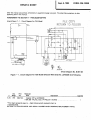 3
3
-
 4
4
-
 5
5
-
 6
6
-
 7
7
-
 8
8
-
 9
9
-
 10
10
-
 11
11
-
 12
12
-
 13
13
-
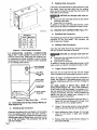 14
14
-
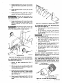 15
15
-
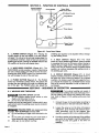 16
16
-
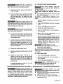 17
17
-
 18
18
-
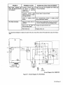 19
19
-
 20
20
-
 21
21
-
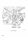 22
22
-
 23
23
-
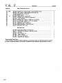 24
24
-
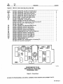 25
25
-
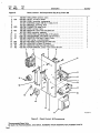 26
26
-
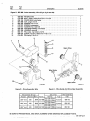 27
27
-
 28
28
-
 29
29
-
 30
30


Miller JC629243 Owner's manual
- Category
- Welding System
- Type
- Owner's manual
- This manual is also suitable for
Ask a question and I''ll find the answer in the document
Finding information in a document is now easier with AI
Related papers
Other documents
-
MK 317/318/319 Owner's manual
-
 MK Products PA-M1 User manual
-
-
 MK Products 091-0593 User manual
-
Python 248-8XX User manual
-
WIA W18 4rd Wirefeeder Owner's manual
-
Graham Field JB0150-085, JB0150-086 User manual
-
 Kreg Screw Gun & Hose Set for Framing Table User manual
-
Interlogix 1038 Series Installation guide
-
 Rockwell Automation 1485P KwikLink Installation guide


