Page is loading ...

31538A - May 2004 - Confidential 1
*This processor operates at 400 MHz. Model numbers reflect performance as described here: http://www.amd.com/connectivitysolutions/geodegxbenchmark.
AMD Geode™ GX DB533
Development Board Overview
1.0 General Description
The AMD Geode™ GX DB533 is designed around the
AMD Geode™ GX [email protected] processor* and the AMD
Geode CS5535 companion device. This board enables a
developer to write and test code, and simulate hardware for
mobile, thin client, and general embedded applications in a
stable and reusable system. The system could be used in
the final product without modification.
This platform consists of two boards: the CPU module
board and base board. The two-board configuration
enables customers to quickly develop a wider range of
products targeted at different applications. Initial develop-
ment can be with the base board and one of the available
CPU module boards (Geode GX DB533-TC for CRT inter-
face or Geode GX DB533-TT for TFT interface). If desired,
the customer can develop their own base board for use
with either of the CPU module boards.
This design uses Advantech’s SOM 144 method of inter-
connection. The Geode GX DB533 kit can be purchased
from AMD (i.e., -TC and -TT) while the boards can be indi-
vidually purchased from Advantech. Contact your local
Advantech representative for additional information.
BIOS is provided by Insyde Software’s XpressROM (pre-
programmed device installed) and General Software’s
Embedded BIOS (preprogrammed device in kit).
The primary functions of the AMD Geode GX DB533 are:
• Development and validation of software:
— Application software for design concept
— BIOS firmware validation
• Development of hardware-based products:
— Design development and emulation
— Proof-of-concept
— Embedded product
• Evaluation of on-board silicon:
— Geode GX [email protected] processor*
— Geode CS5535 companion device

2 AMD Geode™ GX DB533 Development Board Overview
31538A - May 2004 - Confidential
Overview
2.0 Features
Processor, Chipset, and Supporting Chips
■ AMD Geode™ GX [email protected] processor
■ AMD Geode™ CS5535 companion device
■ 128 MB DDR (Double Data Rate) SDRAM
■ AC97 codec
■ National Semiconductor PC87364 LPC SuperI/O
■ National Semiconductor DP83816 LAN controller
■ 2 Mbit FWH (Firmware Hub) boot Flash ROM in a 32-pin
PLCC socket
■ Alternate Advantech configuration supports different
SIO (SuperI/O) and LAN (Local Area Network) on CPU
module.
Standard Connectors, Configurations, and Interfaces
■ Three PCI slots (see AMD Geode™ GX DB533 Devel-
opment Board User’s Guide for operational details):
— Two 3.3V, 66 MHz capable
— One 33 MHz, 5V tolerant
■ One ATA-5 (UltraDMA 66) IDE interface (supports two
devices)
■ One CompactFlash connector (on IDE)
■ Two USB v1.1 port connectors (standard plug)
■ Individual PS/2 keyboard and mouse connectors (from
SIO)
■ FDD (Floppy Disk Drive) connector (from SIO)
■ DB-9 RS232 serial connector (from SIO)
■ 10-pin header for RS232 (from SIO)
■ DB-25 LPT (Line Printer Terminal) connector (from SIO)
■ VGA analog monitor (non-operational in TFT configura-
tion)
■ LCD header (for LCD panel or LVDS module) (non oper-
ational in CRT configuration)
■ Backlight inverter power connector
■ Brightness control via software (2-wire serial interface)
or hardware (variable resistor)
— LCD panel configuration selection jumper
■ Infrared header
■ Audio:
— Mic In, Line In, Line out
— CD In and Aux in
■ 2x13 header for LPC (Low Pin Count) interface
■ LEDs for UDMA, HDD, Power and 3.3VSB
■ PC buzzer
■ RJ-45 Ethernet connector
Memory and Flash Configurations
■ 128 MB DDR SDRAM (four 16MBx16 soldered down)
■ BootROM options:
— 3.3V FWH 2 Mbit sector-erase (from LPC interface)
— LPC ROM (off of LPC)
— NOR Flash (off of IDE)
■ Embedded EEPROM for storing system parameters and
boot options
■ Real-time clock with 242 bytes of bank-selectable
CMOS memory
Software Support
■ Operating System support:
—Linux 2.4
— Windows
®
CE 4.2
— Windows XPe
■ Firmware: XpressROM
— Provides standard BIOS functionality
— AMD’s VSA2 (Virtual System Architecture™) tech-
nology for legacy functions:
– Power management
– 16-bit audio
— Legacy USB support
— Stored in FlashROM
— Pre-boot execution environment integration code
■ Embedded BIOS
— Available from General Software, Inc.,
www.gensw.com, tel. (800) 850-5755
— Pre-programmed PLCC supplied with kit
— Full industry-standard BIOS functionality
— Premium features
— Firmbase 32-bit SMM operating environment
— Support for all industry-standard Operating Systems
(OS)

AMD Geode™ GX DB533 Development Board Overview 3
31538A - May 2004 - Confidential
Overview
Mechanical
■ FlexATX form-factor (229 mm x 191 mm)
■ Soft On/Off, Sleep, Reset controls
Power, Management, and Control Options
■ Standard ATX I/O
■ On-board regulators for the Geode GX processor and
Geode CS5535 companion device core, V
MEM
and
VREF
■ Support for Suspend-to-RAM
■ National Semiconductor LM82 for CPU temperature
monitoring
Standard Interfaces
■ IrDA-compliant interface
■ IDE and CompactFlash support
■ Two-port OHCI (Open Host Controller Interface) USB
implementation
■ AC97 v2.1 compliant audio
■ VGA DDC2 support up to 1600x1200x8 bpp
Test Connectors, Configurations, and Interfaces
■ FS2/JTAG header for Geode GX processor and Geode
CS5535 companion device (Daisy Chain mode)

4 AMD Geode™ GX DB533 Development Board Overview
31538A - May 2004 - Confidential
Overview
3.0 System Architecture
The CPU module board is offered with either a CRT inter-
face (-TC) or a TFT interface (-TT). The base board is
equipped to handle either interface.
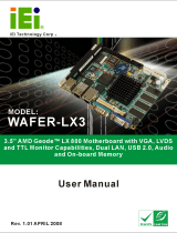
Figure 3-1 is a block diagram of the CPU module board
showing both the CRT and TFT interfaces. Figure 3-2 on
page 5 provides a block diagram of the base board and
illustrates how it connects with the CPU module board.
Figure 3-1. CPU Module Board Block Diagram
10/100
Ethernet
(not installed)
144-Pin Connector
128 MB DDR
SDRAM
AMD Geode™
Clock
Generator
AMD Geode™
CS5535
Companion
Device
Processor*
Battery
USB Host x4
IDE
AC97 v2.1
PS2, SER
80-Pin Connector
Analog RGB (-TC only)
40-Pin Connector
(-TT only)
SMB
Power Control
LPC
LPC SIO
(not installed)
BIOS
Power
Supplies
V
CORE
V
MEM
V
TT
V
IO
V
IO_VSB
AMD Geode Device
Component
Connector
*This processor operates at 400 MHz. Model numbers reflect performance as described here:
http://www.amd.com/connectivitysolutions/geodegxbenchmark.

AMD Geode™ GX DB533 Development Board Overview 5
31538A - May 2004 - Confidential
Overview
Figure 3-2. Base Board Block Diagram
Panel Settings
PCI Slot 2
PCI Slot 1
PCI Slot 0
Isolation/Level Conversion
Arbiter
144-Pin Connector
80-Pin Connector
Audio
Codec
LAN
CD IN
AUX IN
Audio LAN
40-Pin (for TFT)
Termination
Speed IR
40-Pin
PWM
LPC
BRITE Floppy
LPC SIO
USB
PS2
MS/KYBD
VGA COM1
Parallel
SLP
PCI
PCI
SMB
LPC
Buzzer
PWR RST
CompactFlash
Level
Conversion
IDE
I/O EXP
ATX Power
AC97
Tem p
Sense
-TC Interface
-TT Interface
CPU Module Board
COM2
Component
Connector
Switch or Jumper

One AMD Place
P.O. Box 3453,
Sunnyvale, CA 94088-3453 USA
Tel: 408-732-2400 or 800-538-8450
TWX: 910-339-9280
TELEX: 34-6306
TECHNICAL SUPPORT
USA & Canada: 800-222-9323 or 408-749-5703
USA & Canada: PC Microprocessor: 408-749-3060
Latin America Email: spanish.suppor[email protected]
Argentina: 001-800-200-1111, after tone 800-859-4478
Chile: 800-532-853
Mexico: 95-800-222-9323
Europe & UK: +44–0-1276-803299
Fax: +44–0-1276-803298
France: 0800-908-621
Germany: +49–89-450-53199
Italy: 800-877224
Europe Email: euro[email protected]
Far East Fax: 852-2956-0588
Japan Fax: 81-3-3346-7848
TRADEMARKS
AMD, the AMD Arrow logo, and combinations
thereof, and Geode and Virtual System
Architecture are trademarks of
Advanced Micro Devices, Inc.
Windows is a registered trademark of Microsoft
Corporation in the United States and/or other juris-
dictions.
Other product names used in this publication are
for identification purposes only and may be trade-
marks of their respective companies.
www.amd.com
© 2004 Advanced Micro Devices, Inc. All rights reserved.
The contents of this document are provided in connection with Advanced Micro
Devices, Inc. (“AMD”) products. AMD makes no representations or warranties with
respect to the accuracy or completeness of the contents of this publication and
reserves the right to make changes to specifications and product descriptions at
any time without notice. No license, whether express, implied, arising by estoppel
or otherwise, to any intellectual property rights is granted by this publication.
Except as set forth in AMD’s Standard Terms and Conditions of Sale, AMD
assumes no liability whatsoever, and disclaims any express or implied warranty,
relating to its products including, but not limited to, the implied warranty of mer-
chantability, fitness for a particular purpose, or infringement of any intellectual
property right.
AMD’s products are not designed, intended, authorized or warranted for use as
components in systems intended for surgical implant into the body, or in other
applications intended to support or sustain life, or in any other application in which
the failure of AMD’s product could create a situation where personal injury, death,
or severe property or environmental damage may occur. AMD reserves the right to
discontinue or make changes to its products at any time without notice.
/