Page is loading ...


NB-IoT Module Series
BC95&BC95-G&BC68 Application Design Guide
BC95&BC95-G&BC68_Application_Design_Guide 1 / 22
Our aim is to provide customers with timely and comprehensive service. For any
assistance, please contact our company headquarters:
Quectel Wireless Solutions Co., Ltd.
7th Floor, Hongye Building, No.1801 Hongmei Road, Xuhui District, Shanghai 200233, China
Tel: +86 21 5108 6236
Email: [email protected]om
Or our local office. For more information, please visit:
http://quectel.com/support/sales.htm
For technical support, or to report documentation errors, please visit:
http://quectel.com/support/technical.htm
Or email to: support@quectel.com
GENERAL NOTES
QUECTEL OFFERS THE INFORMATION AS A SERVICE TO ITS CUSTOMERS. THE INFORMATION
PROVIDED IS BASED UPON CUSTOMERS’ REQUIREMENTS. QUECTEL MAKES EVERY EFFORT
TO ENSURE THE QUALITY OF THE INFORMATION IT MAKES AVAILABLE. QUECTEL DOES NOT
MAKE ANY WARRANTY AS TO THE INFORMATION CONTAINED HEREIN, AND DOES NOT ACCEPT
ANY LIABILITY FOR ANY INJURY, LOSS OR DAMAGE OF ANY KIND INCURRED BY USE OF OR
RELIANCE UPON THE INFORMATION. ALL INFORMATION SUPPLIED HEREIN IS SUBJECT TO
CHANGE WITHOUT PRIOR NOTICE.
COPYRIGHT
THE INFORMATION CONTAINED HERE IS PROPRIETARY TECHNICAL INFORMATION OF
QUECTEL WIRELESS SOLUTIONS CO., LTD. TRANSMITTING, REPRODUCTION, DISSEMINATION
AND EDITING OF THIS DOCUMENT AS WELL AS UTILIZATION OF THE CONTENT ARE
FORBIDDEN WITHOUT PERMISSION. OFFENDERS WILL BE HELD LIABLE FOR PAYMENT OF
DAMAGES. ALL RIGHTS ARE RESERVED IN THE EVENT OF A PATENT GRANT OR
REGISTRATION OF A UTILITY MODEL OR DESIGN.
Copyright © Quectel Wireless Solutions Co., Ltd. 2018. All rights reserved.

NB-IoT Module Series
BC95&BC95-G&BC68 Application Design Guide
BC95&BC95-G&BC68_Application_Design_Guide 2 / 22
About the Document
History
Revision
Date
Author
Description
1.0
2018-06-20
Hayden WANG/
Evan WU
Initial

NB-IoT Module Series
BC95&BC95-G&BC68 Application Design Guide
BC95&BC95-G&BC68_Application_Design_Guide 3 / 22
Contents
About the Document ................................................................................................................................... 2
Contents ....................................................................................................................................................... 3
Table Index ................................................................................................................................................... 4
Figure Index ................................................................................................................................................. 5
1 Introduction .......................................................................................................................................... 6
2 Application Design Guidelines ........................................................................................................... 7
2.1. Fixed Applications with Data Transmission ............................................................................... 7
2.1.1. Requirements on Network Configurations ....................................................................... 7
2.1.2. Application Design Guidelines ......................................................................................... 8
2.1.3. Flowchart of Design Guidelines ..................................................................................... 10
2.2. Fixed Applications with Remote Control .................................................................................. 11
2.2.1. Requirements on Network Configurations ..................................................................... 11
2.2.2. Application Design Guidelines ....................................................................................... 11
2.2.3. Flowchart of Design Guidelines ..................................................................................... 13
2.3. Mobile Applications with Data Transmission ........................................................................... 14
2.3.1. Requirements on Network Configurations ..................................................................... 14
2.3.2. Application Design Guidelines ....................................................................................... 14
2.3.3. Flowchart of Design Guidelines ..................................................................................... 16
2.4. Mobile Applications with Remote Control ................................................................................ 17
2.4.1. Requirements on Network Configurations ..................................................................... 17
2.4.2. Application Design Guidelines ....................................................................................... 17
2.4.3. Flowchart of Design Guidelines ..................................................................................... 19
3 Supplementary Notes ........................................................................................................................ 20
3.1. Conventional Maintenance and Test Means ........................................................................... 20
3.2. Brief Introduction of Related AT Commands ........................................................................... 20
4 Appendix A References ..................................................................................................................... 22

NB-IoT Module Series
BC95&BC95-G&BC68 Application Design Guide
BC95&BC95-G&BC68_Application_Design_Guide 4 / 22
Table Index
TABLE 1: REQUIREMENTS ON NETWORK CONFIGURATIONS FOR FIXED APPLICATIONS WITH DATA
TRANSMISSION ................................................................................................................................ 7
TABLE 2: DESIGN GUIDELINES FOR FIXED APPLICATIONS WITH DATA TRANSMISSION ........................ 8
TABLE 3: REQUIREMENTS ON NETWORK CONFIGURATIONS FOR FIXED APPLICATIONS WITH
REMOTE CONTROL ......................................................................................................................... 11
TABLE 4: DESIGN GUIDELINES FOR FIXED APPLICATIONS WITH REMOTE CONTROL .......................... 11
TABLE 5: REQUIREMENTS ON NETWORK CONFIGURATIONS FOR MOBILE APPLICATIONS WITH DATA
TRANSMISSION ............................................................................................................................... 14
TABLE 6: DESIGN GUIDELINES FOR MOBILE APPLICATIONS WITH DATA TRANSMISSION ................... 14
TABLE 7: REQUIREMENTS ON NETWORK CONFIGURATIONS FOR MOBILE APPLICATIONS WITH
REMOTE CONTROL ........................................................................................................................ 17
TABLE 8: DESIGN GUIDELINES FOR MOBILE APPLICATIONS WITH REMOTE CONTROL ...................... 17
TABLE 9: BRIEF INTRODUCTION OF RELATED AT COMMANDS ................................................................ 20
TABLE 10: REFERENCE DOCUMENTS .......................................................................................................... 22
TABLE 11: TERMS AND ABBREVIATIONS ...................................................................................................... 22

NB-IoT Module Series
BC95&BC95-G&BC68 Application Design Guide
BC95&BC95-G&BC68_Application_Design_Guide 5 / 22
Figure Index
FIGURE 1: FLOWCHART OF DESIGN GUIDELINES FOR FIXED APPLICATIONS WITH DATA
TRANSMISSION ............................................................................................................................ 10
FIGURE 2: FLOWCHART OF DESIGN GUIDELINES FOR FIXED APPLICATIONS WITH REMOTE
CONTROL ....................................................................................................................................... 13
FIGURE 3: FLOWCHART OF DESIGN GUIDELINES FOR MOBILE APPLICATIONS WITH DATA
TRANSMISSION ............................................................................................................................. 16
FIGURE 4: FLOWCHART OF DESIGN GUIDELINES FOR MOBILE APPLICATIONS WITH REMOTE
CONTROL ....................................................................................................................................... 19

NB-IoT Module Series
BC95&BC95-G&BC68 Application Design Guide
BC95&BC95-G&BC68_Application_Design_Guide 6 / 22
1 Introduction
At present, Quectel NB-IoT modules are mainly applied to following application scenarios:
⚫ Fixed applications with data transmission: such as water meters, gas meters and smoke detectors.
⚫ Fixed applications with remote control: such as street lights and shared laundry machines.
⚫ Mobile applications with data transmission: such as shared bicycles and activity trackers.
⚫ Mobile applications with remote control: such as electric motor controllers.
This document illustrates design guidelines for the four application scenarios mentioned above in order to
help customers deploy NB-IoT terminals based on Quectel NB-IoT modules under different network
deployment environments, such as a change on EARFCN (E-UTRA Absolute Radio Frequency Channel
Number) values and a switch from intra-frequency to inter-frequency.
This document is applicable to following Quectel NB-IoT modules:
⚫ BC95 B657SP5 version or later
⚫ BC35-G B300 version or later
⚫ BC28 B300 version or later

NB-IoT Module Series
BC95&BC95-G&BC68 Application Design Guide
BC95&BC95-G&BC68_Application_Design_Guide 7 / 22
2 Application Design Guidelines
This chapter provides design guidelines and recommendations for different application scenarios of
Quectel NB-IoT modules.
2.1. Fixed Applications with Data Transmission
Fixed applications with data transmission feature a fixed deployment location and periodic data
transmission service. They are kept in sleep mode most of the time, and they only receive downlink data
when an uplink data transmission is initiated (no need for receiving paging messages). Such terminals
have high requirements on power consumption and success rate of data transmission rather than the
timeliness of data transmission. Therefore, it is recommended to comply with the following design
requirements.
2.1.1. Requirements on Network Configurations
Table 1: Requirements on Network Configurations for Fixed Applications with Data Transmission
Please confirm the configuration settings of these parameters with corresponding network operators since
they are determined by the core network.
No.
Parameter
Configuration Requirement
1
eDRX
Disabled
2
PSM
Enabled
NOTE

NB-IoT Module Series
BC95&BC95-G&BC68 Application Design Guide
BC95&BC95-G&BC68_Application_Design_Guide 8 / 22
2.1.2. Application Design Guidelines
Table 2: Design Guidelines for Fixed Applications with Data Transmission
No.
Design Guideline
Description
1
Timeout period for the MCU to
register on network after start-up
It may take a long time for the MCU to register on network
when in deep coverage or when the network changes, so
the timeout period for the MCU to register on network after
start-up is recommended to be at least 300s.
2
Enable cell reselection function
a) In order to ensure that the module can be camped on a
better cell in terms of signal strength and quality, it is
recommended to enable the cell reselection function of
the module. For BC95 B657SP5 or later versions,
BC95-G B300 or later versions, and BC68 B300 or later
versions, the cell reselection function is enabled by
default.
b) If the cell reselection function is disabled, the MCU can
send AT+NCONFIG=CELL_RESELECTION, TRUE to
enable the cell reselection function when the module is
in minimum function mode (AT+CFUN=0).
3
Start an uplink data transmission
with RAI identifiers
Start an uplink data transmission with RAI identifiers (e.g.:
AT+QLWULDATAEX=3,AA34BB,0x0001) for indicating the
core network to release current RRC connection
immediately so as to let the module enter idle mode. Then
the module will automatically enter PSM after the idle timer
expires.
4
If the module is powered off by the
MCU, it must delay for at least 15s
after the module enters idle mode
After the module enters idle mode, it must wait for at least
15s before powering off the module, so that the network can
configure the T3324 timer to ensure the module has enough
time to complete the cell reselection procedure.
5
If the module is powered off by the
MCU, AT+CFUN=0 must be
executed before power-off.
Before powering off the module, the MCU needs to send
AT+CFUN=0 command to the module to trigger the module
to save the EARFCN values and send a message to detach
from network.
6
Data transmission service
a) When starting a data transmission via Huawei
OceanConnect IoT platform or China Telecom EasyIoT
platform, if "+CME ERROR: 513" error is returned
(AT+CMEE=1 has been set; 513: TUP not registered),
the MCU will attempt to re-send the data after a delay of
20s; if the re-send is failed for 3 times continuously, the
MCU will enter the exception handling process (Refer
to No.7 below).

NB-IoT Module Series
BC95&BC95-G&BC68 Application Design Guide
BC95&BC95-G&BC68_Application_Design_Guide 9 / 22
b) During a normal data transmission, if no downlink data
is received within 60s in data interaction process, it will
be regarded as a data service failure due to timeout,
and the MCU will attempt to re-send the data; if the
re-send is failed for 3 times continuously, the MCU will
enter the exception handling process (Refer to No.7
below).
7
Exception handling process
If it fails to register on network or transmit data, then the
MCU executes AT+NRB (Reboot the module) →
AT+CFUN=0 (Enter minimum functionality mode) →
AT+NCSEARFCN (Clear Stored EARFCN values) →
AT+CFUN=1 (Enter full functionality mode) →
AT+CGATT=1 (Attach to network), and tries to register on
network and re-sends the data. If the re-registration or
re-send still fails, it will retry for 3 times according to the
back off algorithm. If it still fails, the MCU will power off the
module. In such case, the module will try to register on
network when the next round of data transmission is
initiated.
8
Support the module’s firmware
upgrade via DFOTA
During a firmware upgrade process via DFOTA, no AT
command can be sent and the module cannot be powered
off. It is recommended that the uninterruptible power supply
time should be 30 minutes. The module outputs
"FIRMWARE DOWNLOADING" via the main port to
indicate that the firmware has started upgrading, and
"FIRMWARE UPDATE OVER" to indicate that the upgrade
is completed and successful.

NB-IoT Module Series
BC95&BC95-G&BC68 Application Design Guide
BC95&BC95-G&BC68_Application_Design_Guide 10 / 22
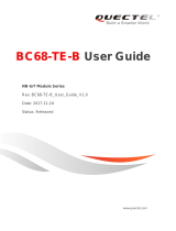
2.1.3. Flowchart of Design Guidelines
Power off
Network attachment
Query whether successfully
registered on network
AT+CGATT?
Data
transmission
service
Whether the data is
transmitted successfully?
Yes
Start an uplinlk data
transmission with
RAI identifiers.
Reboot the module
AT+NRB
Whether retry to
register on network?
Enter minimum
functionality mode
AT+CFUN=0
Clear stored
EARFCN values
AT+NCSEARFCN
Trigger network
attachment
AT+CFUN=1
AT+CGATT=1
Yes
Exception
Handling
No
No
No
Fail to receive downlink
data 3 times continuously
due to timeout (60s).
Failed after 3 times of retries
according to the back off
algorithm.
Idle mode
PSM
Yes
Whether to power
off the module?
It is recommended to enter the PSM. If
it needs to power off the module, it is
recommended to wait for at least 15s
after entering idle mode, and execute
AT+CFUN=0 before powering off the
module.
AT+CFUN=0
YN
Power on the module
Set to manually register on network
AT+NCONFIG=AUTOCONNECT,FALSE
Enter full functionality mode
AT+CFUN=1
Trigger network attachment
AT+CGATT=1
Set CDP server address
AT+NCDP=<ip_addr>[,<port>] Skip this step for
UDP/TCP server
Specify band values
AT+NBAND=<n> Skip this step for
BC95 module
Reboot the module by software
AT+NRB
Disable eDRX function of the module
AT+CEDRXS=0,5
Execute AT+CGATT? after
300s, "+CGATT:1" is not
returned.
Figure 1: Flowchart of Design Guidelines for Fixed Applications with Data Transmission

NB-IoT Module Series
BC95&BC95-G&BC68 Application Design Guide
BC95&BC95-G&BC68_Application_Design_Guide 11 / 22
2.2. Fixed Applications with Remote Control
Fixed applications with remote control feature a fixed deployment location. They are usually powered with
an external power supply and kept in connected mode most of the time. Meanwhile, they are required to
receive real-time downlink data. Such terminals have high requirements on timeliness of data
transmission rather than power consumption. Therefore, it is recommended to comply with the following
design requirements.
2.2.1. Requirements on Network Configurations
Table 3: Requirements on Network Configurations for Fixed Applications with Remote Control
Please confirm the configuration settings of these parameters with corresponding network operators since
they are determined by the core network.
2.2.2. Application Design Guidelines
Table 4: Design Guidelines for Fixed Applications with Remote Control
No.
Parameter
Configuration Requirement
1
eDRX
Disabled
2
PSM
Disabled
No.
Design Guideline
Description
1
Timeout period for the MCU to
register on network after start-up
It may take a long time for the MCU to register on network
when in deep coverage or when the network changes, so
the timeout period for the MCU to register on network after
start-up is recommended to be at least 300s.
2
Enable cell reselection function
a) In order to ensure that the module can be camped on a
better cell in terms of signal strength and quality, it is
recommended to enable the cell reselection function of
the module. For BC95 B657SP5 or later versions,
BC95-G B300 or later versions, and BC68 B300 or later
versions, the cell reselection function is enabled by
default.
NOTE

NB-IoT Module Series
BC95&BC95-G&BC68 Application Design Guide
BC95&BC95-G&BC68_Application_Design_Guide 12 / 22
b) If the cell reselection function is disabled, the MCU can
send AT+NCONFIG=CELL_RESELECTION, TRUE to
enable the cell reselection function when the module is
in minimum function mode (AT+CFUN=0).
3
If the module is powered off by the
MCU, AT+CFUN=0 must be
executed before power-off.
Before powering off the module, the MCU needs to send
AT+CFUN=0 command to the module to trigger the module
to save the EARFCN values and send a message to detach
from network.
4
Data transmission service
a) When starting a data transmission via Huawei
OceanConnect IoT platform or China Telecom EasyIoT
platform, if "+CME ERROR: 513" error is returned
(AT+CMEE=1 has been set; 513: TUP not registered),
the MCU will attempt to re-send the data after a delay of
20s; if the re-send is failed for 3 times continuously, the
MCU will enter the exception handling process (Refer
to No.5 below).
b) During a normal data transmission, if no downlink data
is received within 60s in data interaction process, it will
be regarded as a data service failure due to timeout,
and the MCU will attempt to re-send the data; if the
re-send is failed for 3 times continuously, the MCU will
enter the exception handling process (Refer to No.5
below).
5
Exception handling process
If it fails to register on network or transmit data, then the
MCU executes AT+NRB (Reboot the module) →
AT+CFUN=0 (Enter minimum functionality mode) →
AT+NCSEARFCN (Clear Stored EARFCN values) →
AT+CFUN=1 (Enter full functionality mode) →
AT+CGATT=1 (Attach to network), and tries to register on
network and re-sends the data. If the re-registration or
re-send still fails, it will retry for 3 times according to the
back off algorithm. If it still fails, the MCU will power off the
module. In such case, the module will try to register on
network when the next round of data transmission is
initiated.
6
Support the module’s firmware
upgrade via DFOTA
During a firmware upgrade process via DFOTA, no AT
command can be sent and the module cannot be powered
off. It is recommended that the uninterruptible power supply
time should be 30 minutes. The module outputs
"FIRMWARE DOWNLOADING" via the main port to
indicate that the firmware has started upgrading, and
"FIRMWARE UPDATE OVER" to indicate that the upgrade
is completed and successful.

NB-IoT Module Series
BC95&BC95-G&BC68 Application Design Guide
BC95&BC95-G&BC68_Application_Design_Guide 13 / 22
2.2.3. Flowchart of Design Guidelines
Power off
Network attachment
Query whether successfully
registered on network
AT+CGATT?
Data
transmission
service
Whether the data is
transmitted successfully?
Yes
Reboot the module
AT+NRB
Whether retry to
register on network?
Enter minimum
functionality mode
AT+CFUN=0
Clear stored
EARFCN values
AT+NCSEARFCN
Trigger network
attachment
AT+CFUN=1
AT+CGATT=1
Yes
Exception
Handling
No
No
No
Fail to receive downlink
data 3 times continuously
due to timeout (60s).
Failed after 3 times of retries
according to the back off
algorithm.
Idle mode
Yes
Power on the module
Set to manually register on network
AT+NCONFIG=AUTOCONNECT,FALSE
Enter full functionality mode
AT+CFUN=1
Trigger network attachment
AT+CGATT=1
Set CDP server address
AT+NCDP=<ip_addr>[,<port>] Skip this step for
UDP/TCP server
Specify band values
AT+NBAND=<n> Skip this step for
BC95 module
Reboot the module by software
AT+NRB
Disable eDRX function of the module
AT+CEDRXS=0,5
Disable the use of PSM
AT+CPSMS=0
Execute AT+CGATT? after
300s, "+CGATT:1" is not
returned.
Figure 2: Flowchart of Design Guidelines for Fixed Applications with Remote Control

NB-IoT Module Series
BC95&BC95-G&BC68 Application Design Guide
BC95&BC95-G&BC68_Application_Design_Guide 14 / 22
2.3. Mobile Applications with Data Transmission
Mobile applications with data transmission will start a data transmission while they are moving. They only
receive downlink data when an uplink data transmission is initiated (no need for receiving paging
messages). Such terminals have high requirements on power consumption rather than timeliness of data
transmission. Therefore, it is recommended to comply with the following design requirements.
2.3.1. Requirements on Network Configurations
Table 5: Requirements on Network Configurations for Mobile Applications with Data Transmission
Please confirm the configuration settings of these parameters with corresponding network operators since
they are determined by the core network.
2.3.2. Application Design Guidelines
Table 6: Design Guidelines for Mobile Applications with Data Transmission
No.
Parameter
Configuration Requirement
1
eDRX
Disabled
2
PSM
Enabled
No.
Design Guideline
Description
1
Timeout period for the MCU to
register on network after start-up
It may take a long time for the MCU to register on network
when in deep coverage or when the network changes, so
the timeout period for the MCU to register on network after
start-up is recommended to be at least 300s.
2
Enable cell reselection function
a) In order to ensure that the module can be camped on a
better cell in terms of signal strength and quality, it is
recommended to enable the cell reselection function of
the module. For BC95 B657SP5 or later versions,
BC95-G B300 or later versions, and BC68 B300 or later
versions, the cell reselection function is enabled by
default.
b) If the cell reselection function is disabled, the MCU can
NOTE

NB-IoT Module Series
BC95&BC95-G&BC68 Application Design Guide
BC95&BC95-G&BC68_Application_Design_Guide 15 / 22
send AT+NCONFIG=CELL_RESELECTION, TRUE to
enable the cell reselection function when the module is
in minimum function mode (AT+CFUN=0).
3
Start an uplink data transmission
with RAI identifiers
Start an uplink data transmission with RAI identifiers (e.g.:
AT+QLWULDATAEX=3,AA34BB,0x0001) for indicating the
core network to release current RRC connection
immediately so as to let the module enter idle mode. Then
the module will automatically enter PSM after the idle timer
expires.
4
If the module is powered off by the
MCU, AT+CFUN=0 must be
executed before power-off.
Before powering off the module, the MCU needs to send
AT+CFUN=0 command to the module to trigger the module
to save the EARFCN values and send a message to detach
from network.
5
Data transmission service
a) When starting a data transmission via Huawei
OceanConnect IoT platform or China Telecom EasyIoT
platform, if "+CME ERROR: 513" error is returned
(AT+CMEE=1 has been set; 513: TUP not registered),
the MCU will attempt to re-send the data after a delay of
20s; if the re-send is failed for 3 times continuously, the
MCU will enter the exception handling process (Refer
to No.6 below).
b) During a normal data transmission, if no downlink data
is received within 60s in data interaction process, it will
be regarded as a data service failure due to timeout,
and the MCU will attempt to re-send the data; if the
re-send is failed for 3 times continuously, the MCU will
enter the exception handling process (Refer to No.6
below).
6
Exception handling process
If it fails to register on network or transmit data, then the
MCU executes AT+NRB (Reboot the module) →
AT+CFUN=0 (Enter minimum functionality mode) →
AT+NCSEARFCN (Clear Stored EARFCN values) →
AT+CFUN=1 (Enter full functionality mode) →
AT+CGATT=1 (Attach to network), and tries to register on
network and re-sends the data. If the re-registration or
re-send still fails, it will retry for 3 times according to the
back off algorithm. If it still fails, the MCU will power off the
module. In such case, the module will try to register on
network when the next round of data transmission is
initiated.
7
Support the module’s firmware
upgrade via DFOTA
During a firmware upgrade process via DFOTA, no AT
command can be sent and the module cannot be powered
off. It is recommended that the uninterruptible power supply
time should be 30 minutes. The module outputs

NB-IoT Module Series
BC95&BC95-G&BC68 Application Design Guide
BC95&BC95-G&BC68_Application_Design_Guide 16 / 22
2.3.3. Flowchart of Design Guidelines
Power off
Network attachment
Query whether successfully
registered on network
AT+CGATT?
Data
transmission
service
Whether the data is
transmitted successfully?
Yes
Start an uplink data
transmission with
RAI identifiers.
Reboot the module
AT+NRB
Whether retry to
register on network?
Enter minimum
functionality mode
AT+CFUN=0
Clear stored
EARFCN values
AT+NCSEARFCN
Trigger network
attachment
AT+CFUN=1
AT+CGATT=1
Yes
Exception
Handling
No
No
No
Fail to receive downlink
data 3 times continuously
due to timeout (60s).
Failed after 3 times of retries
according to the back off
algorithm.
Idle mode
Yes
Power on the module
Set to manually register on network
AT+NCONFIG=AUTOCONNECT,FALSE
Enter full functionality mode
AT+CFUN=1
Trigger network attachment
AT+CGATT=1
Set CDP server address
AT+NCDP=<ip_addr>[,<port>] Skip this step for
UDP/TCP server
Specify band values
AT+NBAND=<n> Skip this step for
BC95 module
Reboot the module by software
AT+NRB
Disable eDRX function of the module
AT+CEDRXS=0,5
Execute AT+CGATT? after
300s, "+CGATT:1" is not
returned.
PSM
Figure 3: Flowchart of Design Guidelines for Mobile Applications with Data Transmission
"FIRMWARE DOWNLOADING" via the main port to
indicate that the firmware has started upgrading, and
"FIRMWARE UPDATE OVER" to indicate that the upgrade
is completed and successful.

NB-IoT Module Series
BC95&BC95-G&BC68 Application Design Guide
BC95&BC95-G&BC68_Application_Design_Guide 17 / 22
2.4. Mobile Applications with Remote Control
Mobile applications with remote control are kept in a moving state and in connected mode most of the
time. They are required to receive real-time downlink data and report real-time uplink data. Such terminals
are usually rechargeable and have high requirements on timeliness of data transmission rather than
power consumption. Therefore, it is recommended to comply with the following design requirements.
2.4.1. Requirements on Network Configurations
Table 7: Requirements on Network Configurations for Mobile Applications with Remote Control
Please confirm the configuration settings of these parameters with corresponding network operators since
they are determined by the core network.
2.4.2. Application Design Guidelines
Table 8: Design Guidelines for Mobile Applications with Remote Control
No.
Parameter
Configuration Requirement
1
eDRX
Disabled
2
PSM
Disabled
No.
Design Guideline
Description
1
Timeout period for the MCU to
register on network after
start-up
It may take a long time for the MCU to register on network
when in deep coverage or when the network changes, so the
timeout period for the MCU to register on network after start-up
is recommended to be at least 300s.
2
Enable cell reselection function
a) In order to ensure that the module can be camped on a
better cell in terms of signal strength and quality, it is
recommended to enable the cell reselection function of the
module. For BC95 B657SP5 or later versions, BC95-G
B300 or later versions, and BC68 B300 or later versions,
the cell reselection function is enabled by default.
b) If the cell reselection function is disabled, the MCU can
send AT+NCONFIG=CELL_RESELECTION, TRUE to
NOTE

NB-IoT Module Series
BC95&BC95-G&BC68 Application Design Guide
BC95&BC95-G&BC68_Application_Design_Guide 18 / 22
enable the cell reselection function when the module is in
minimum function mode (AT+CFUN=0).
3
Start an uplink data
transmission with RAI
identifiers
Start an uplink data transmission with RAI identifiers (e.g.:
AT+QLWULDATAEX=3,AA34BB,0x0001) for indicating the
core network to release current RRC connection immediately
so as to let the module enter idle mode. Then the module will
automatically enter PSM after the idle timer expires.
4
If the module is powered off by
the MCU, AT+CFUN=0 must
be executed before power-off.
Before powering off the module, the MCU needs to send
AT+CFUN=0 command to the module to trigger the module to
save the EARFCN values and send a message to detach from
network.
5
Data transmission service
a) When starting a data transmission via Huawei
OceanConnect IoT platform or China Telecom EasyIoT
platform, if "+CME ERROR: 513" error is returned
(AT+CMEE=1 has been set; 513: TUP not registered), the
MCU will attempt to re-send the data after a delay of 20s; if
the re-send is failed for 3 times continuously, the MCU
will enter the exception handling process (Refer to No.6
below).
b) During a normal data transmission, if no downlink data is
received within 60s in data interaction process, it will be
regarded as a data service failure due to timeout, and the
MCU will attempt to re-send the data; if the re-send is
failed for 3 times continuously, the MCU will enter the
exception handling process (Refer to No.6 below).
6
Exception handling process
If it fails to register on network or transmit data, then the MCU
executes AT+NRB (Reboot the module) → AT+CFUN=0 (Enter
minimum functionality mode) → AT+NCSEARFCN (Clear
Stored EARFCN values) → AT+CFUN=1 (Enter full
functionality mode) → AT+CGATT=1 (Attach to network), and
tries to register on network and re-sends the data. If the
re-registration or re-send still fails, it will retry for 3 times
according to the back off algorithm. If it still fails, the MCU will
power off the module. In such case, the module will try to
register on network when the next round of data transmission is
initiated.
7
Support the module’s firmware
upgrade via DFOTA
During a firmware upgrade process via DFOTA, no AT
command can be sent and the module cannot be powered off.
It is recommended that the uninterruptible power supply time
should be 30 minutes. The module outputs "FIRMWARE
DOWNLOADING" via the main port to indicate that the
firmware has started upgrading, and "FIRMWARE UPDATE
OVER" to indicate that the upgrade is completed and
successful.

NB-IoT Module Series
BC95&BC95-G&BC68 Application Design Guide
BC95&BC95-G&BC68_Application_Design_Guide 19 / 22
2.4.3. Flowchart of Design Guidelines
Power off
Network attachment
Query whether successfully
registered on network
AT+CGATT?
Data
transmission
service
Whether the data is
transmitted successfully?
Yes
Reboot the module
AT+NRB
Whether retry to
register on network?
Enter minimum
functionality mode
AT+CFUN=0
Clear stored
EARFCN values
AT+NCSEARFCN
Trigger network
attachment
AT+CFUN=1
AT+CGATT=1
Yes
Exception
Handling
No
No
No
Fail to receive downlink
data 3 times continuously
due to timeout (60s).
Failed after 3 times of retries
according to the back off
algorithm.
Idle mode
Yes
Power on the module
Set to manually register on network
AT+NCONFIG=AUTOCONNECT,FALSE
Enter full functionality mode
AT+CFUN=1
Trigger network attachment
AT+CGATT=1
Set CDP server address
AT+NCDP=<ip_addr>[,<port>] Skip this step for
UDP/TCP server
Specify band values
AT+NBAND=<n> Skip this step for
BC95 module
Reboot the module by software
AT+NRB
Disable eDRX function of the module
AT+CEDRXS=0,5
Disable the use of PSM
AT+CPSMS=0
Execute AT+CGATT? after
300s, "+CGATT:1" is not
returned.
Start an uplink data
transmission with
RAI identifiers.
Figure 4: Flowchart of Design Guidelines for Mobile Applications with Remote Control
/