Page is loading ...

Original instructions
User´s manual
MH270
Desiccantdehumidifier
Applies to all units manufactured
from week 50, 2009
190TGB-1012-A1006 © Munters Europe AB 2010

Importantuserinformation
Intendeduseofequipment
Munters dehumidifiers are intended to be used for the
dehumidification of air. All other uses of the equipment,
or use which is contrary to the instructions given in
this manual, can cause personal injury and/or machine
damage
Warrantyandobl
igations
Thewarrantyper
iodis24monthsfromthedatethe
equipment left o
ur factory, unless otherwise advised
in writing. The
warranty is limited to a free exchange
including fre
e freight of the faulty unit or components,
which have fai
led as a result of faulty quality or defects in
manufacture.
Munters guarantees that the unit supplied
has undergon
e thorough tes ting to ensure that it meets
the specifica
tions given here. All warranty claims must
include pro
of that the fault has occurred within the
warranty pe
riod and that the unit has been used in
accordance
with the specifications. All claims must
specify th
e unit type and manufacturing number. This
informati
on is stamped on the unit identification plate,
see the se
ction Marking.
Note!
The contents of this publication can be change d without
prior notice. This publication contains information
which is protected by copyright laws. No part of this
publication may be reproduced, stored in a system for
information retrieval or be transmitted in any form, in
any manner without Munters’ written consent. Please
send any comments regarding the contents of this
publication to:
Munters Europe AB
Dehumidification Division
Technical Documentation
P O Box 1150
SE -
164 26 KISTA Sweden
Tel: +46 8 626 63 00
e-mail: t-doc@munters.se
© Munters Europe AB 2010
Safety
In this publication hazardous activities are indicated and
preceded by the common hazard symbol.
WARNING!
isusedinthispublicationtoindicateapossibledangerthat
couldleadtopersona linjury. Aninstructionisnormallygiven,
followedbyashortexplanation,plusthepossibleeffectsif
theinstructionisnotfollowed.
CAUTION!
isusedinthispublicationtoindicateapossibledangerthat
couldleadtodamagetothemachineorotherequipment
and/orcaus eenvironmentaldamage. Aninstruction
isnormallygiven,followedbyashortexplanation,plus
thepossibleenvironmentaleffectiftheinstructionisnot
followed.
NOTE! Usedtoaccentuatesupplementaryinformation
thatisrequiredforproblem-freeuseoroptimaluseofthe
unit.
Conformitywithdirectivesand
standards
We Munters Europe AB declare that the dehumidifier
is in conformity with the essential health and safety
requirements of the Machinery Directive 2006/42/EC,
the Low Voltage Directive 2006/95/EC and the
EMC Directive 2004/108/EC The dehumidifier
is manufactured by an ISO 9001:2008 accredited
manufacturing organisation.
ii Importantuserinformation 190TGB-1012-A1006

Contents
Importantuserinfor
mation ...............
ii
Intended use of equi
pment ...........
ii
Warrantyandobligations .............
ii
Note! ...................................
ii
Safety ..................................
ii
Conformity wit
h directives and
standards ..............................
ii
Contents ..................................... iii
1 Introduction ................................. 1
1.1 Aboutthismanual .....................
1
1.2 SafetyandCautions ..................
1
1.3 Marking ................................
1
1.4 Scrapping ..............................
1
2 Productdesigninformation ............... 2
2.1 Productdescription ...................
2
2.2 Principleofoperation ..................
2
2.3 Dimen
sionsandservicespace .......
3
3 Installation ................................... 4
3.1 General ................................
4
3.2 Saf
ety ..................................
4
3.
3
Pa
ckaging and delivery inspection ..
5
3
.4
T
ransport ..............................
5
3.5 Storingtheequipment ................
5
3.6 Siterequirements .....................
5
3.7 Duct/hoseconnections ...............
6
3.7.1 General .........................
6
3.7.2 Installationexamples ..........
8
3.8 Electricalconnections ................
9
3.8.1 General ........................
9
3.8.2 Safety ..........................
9
3.9 Connecting the humid
istat ............
9
3.9.1 General .........................
9
3.9.2 Humidistatconnection kit .....
10
3.10 Airflowset-updata ....................
11
3.11 Operation ..............................
13
3.11.1Startingup ......................
13
3.11.2Quickstop ......................
13
3.12 Start ....................................
13
3.12.1Manual oper
ation ..............
13
3.12.2Automaticoperation ...........
13
3.13 Options .................................
14
3.13.1Remote
alarm ..................
14
3.14 Stop ....................................
14
3.15 Cont
inuousFanOperation ...........
15
4 Maintenance ................................ 16
4.1 General ................................
16
4.
2
Sa
fety ..................................
16
4
.3
M
aintenanceschedule ................
17
4.4 Filterreplacement .....................
17
5 Faulttracing ................................. 18
5.1 General ................................
18
5.2 Safety ..................................
18
5.3 Faulttracinglist ........................
19
5.4 Resetting High Temperature
Cut-Out ................................
20
6 Capacitydiagrams ......................... 21
7 Fandiagrams ................................ 22
8 Sounddata .................................. 23
9 Technicalspecification .................... 24
190TGB-1012-A1006 Contents iii

1Introduction
1.1 Aboutthismanual
This manual is written for the user
of the dehumidifier and describes installation, operation, maintenance
and basic fault tracing. The manua
l is divided into numbered chapters and sections. The list of contents on
page iii provides an overview. T
he different chapters can be used independently. Figures and tables are
numbered in accordance with th
e chapters. Example: Figure 1.3 is figure 3 in chapter 1.
1.2 SafetyandCautions
The contents of this manual include sugg e stions for bestworking practices and procedures. These are given
as guidance only and are not intended to replace individual responsibility and/or local safety regulations.
During installation and operation of this equipment, it is always each individual person’s responsibility to
consider:
■ The safety of yourself and others.
■ Thesafeuseofthedehumidifier through the correct use of the equipment in accordance with the
descriptions and instructions given in this manual.
The dehumidifier is designed to meet the safety requirements, directives and standards listed in the EC
Declaration ofConformity. We recommend that the user learns the use of safety symbols in this manual by
reading the Important User Information on page ii. Safety information is listed in the beginning of each chapter
when required.
1.3 Marking
A
Figure 1
.1 Identification label position (A)
Type
Fabr. No. 0919 190XXX XXXXX
1 ~ 230V 50 Hz
0,19 kW
Max
1,99 kW
Munters Europe AB
Isafjordsgatan 1
164 26 Kista, Sweden
M
IP44
Fabr. year
1,8 kW
Made in Sweden
Weight: 22 kg
MH270
2009
Figure 1
.2 Identification label
1.4 Scrapping
The dehumidifier must be handed in for scrapping in accordance with valid regulations. Contact the local
authorities.
1 Introduction 190TGB-1012-A1006

2 Productdesigninformation
2.1 Productdescription
The MH270 desiccant dehumidifier is designed to efficiently dehumidify air. It is designed for extended
periods of operation and has a common fan for both process and reactivation airflows (i.e. a three hole unit).
It contains a distribution chamber with isolated sections that provide a precise balance for dehumidification,
purge, reactivation, and heat recovery airflows. Its rugged formed metal frame and access panels are
produced from corrosion resistant ALUZINK©. The electrical control system conforms to EN 60204-1
standards and the electrical components are assembled behind t he control panel. The MH270 dehumidifiers
conform to both harmonised European Standards and to CE marking speci fications.
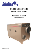
2.2 Principleofoperation
The unit’s rotor is exposed in sectors to different airflows. The airflow that is to be dehumidified is
called process air and passes through the largest sector of the rotor. The moisture in the process air is
deposited into the rotor structure and process air will then leave the rotor as dry air. While the rotor
rotates slowly the incoming process air always meets a dry rotor structure, thus creating a continuous
dehumidification process. T he desiccant rotor structure comprises of a larg e number of narrow and parallel
air channels, processed to a composite material that is highly effective at attracting and holding water vapour.
Simultaneously, a portion of the process air is used as reactivation air and is directed through the pre-purge
and heat recovery sectors in the rotor. This air is then heated and is used to evaporate the moisture from the
reactivation sector of the rotor. T he wet air (warm, moist air) is then vented outside.
A
B
C
1
2
3
4
Figure 2.1 Function overview
A. Wet air
B. Dry air
C. Process/Reactivation air
1. Rotor
2. Fan assembly
3. Reactivation heater
4. Filter
190TGB-1012-A1006 Productdesigninformation 2

2.3 Dimensionsandservicespace
Scaled and dimensioned AutoCAD drawings are available in Munters’ DryCAD prog ram (can be ordered at
your nearest Munters office).
Figure 2.2 Dimensions
1. Process/Reactivation Air Inlet 3. Wet Air O utlet 5. Service Access
2. Dry Air Outlet 4. Airflow Test Points 6. Mode Switch
Width(A) Depth(B) Height(C) Diam . (D) Diam. (E) Service
Space(F)
Service
Space(G)
Weight
430 mm 335 mm 620 mm ∅80 ∅100 450 mm 250 mm 22 kg
Table 2.1 Dimensions and weight
3 Productdesigninformation 190TGB-1012-A1006

3Installation
3.1 General
The MH270 is intended for indoor in
stallation. The unit shall be placed in an upright position on a level
surface. If the unit is store d prio
r to installation, place it in a roofed area, on a level surface where it is
protected from impac t, dust, fr
ost, rain or agg r essive contaminants.
3.2 Safety
WARNING!
Theunitisnotintendedforuseinclassifiedareaswhereexplosionsafetyequipmentisrequired.
WARNING!
Theunitmustnotbesplashedwith,orimmersedinwater.
WARNING!
Donotcovertheunitorobstructtheairvents.
WARNING!
Donotoperatetheunitifthepowerplugorcordisdamaged.
WARNING!
Theunitmustnotbeconnectedtoapowersourceotherthanthatspecifiedonitsidentificationplate.
WARNING!
Theunitshouldbeconnectedtoanearthedelectricalsocket.
WARNING!
Allelectricalequipmentconnectionsmustbecarriedoutinaccordancewithlocalregulationsandbyqualified
personnel.
WARNING!
Donotoperatetheunitnearanyheat-generatingdevices,ornearflammableandhazardousmaterial.
WARNING!
Donotinsertfingersoranyotherobjectsintotheairvents.
WA
RNING!
Do
nottrytorepair,dismantleormodifytheunit.
WARNING!
Theunitmustnotbeopenedbyanyoneotherthantrainedandqualifiedpersonnel.
190TGB-1012-A1006 Installation 4

CAUTION!
Donotsit,stand,orplaceanyobjectsontheunit.
CAUTION!
It hereisariskforfreezingtem p
eratures,thewetairductingmustbeinsulated.
3.3 Packaginganddeliveryinspection
1. Check the delivery ag ainst the packing list, c onsignment note or other delivery documentation and
check that everything is included and nothing is damaged.
2. Contact Munters immediately if delivery is not complete in order to avoid installation delays. Any
visible damage must be reported in writing to Munters within five days and prior to unit installation.
3. If the unit is to be put into storage prior to installation, see section 3.5, Storing the equipment .
NOTE!
Iftheinstallationisnottobecarriedoutimmediatelyafterthearrivaloftheequipmentitisadvisable
toleavethepackagingmaterialinplaceonthedehumidifier,ortore-usethepackagingmaterialtoprovide
temperatureprotectionfortheunitduringlatertransporttoinstallationsiteandduringinstallation.
3.4 Transport
Use the handle when lifting the dehumidifier. If possible, use a pallet loader to move the dehumidifier. It is
recommended to use the original packaging w hen shipping the dehumidifier.
3.5 Storingtheequipment
The following i
s important if the dehumidifier is to be stored prior to installation:
■ Place the dehumidifier on a horizontal surface.
■ Protect the dehumidifier from physical damage
■ Store the dehumidifier under cover and protect it from dust, frost, rain and aggressive contaminants
3.6 Siterequirements
The dehumidifier is only intended for indoor installation. The unit should be placed in an upright position
on a level floor, or platform. Avoid installing the dehumidifier where there is a risk of water entering the unit,
or in a very dusty environment. Refer to Munters for advice if in doubt.
For unit and service dim ensions, see section 9, Technical specification.
NOTE!
Itisimportantthattheintendedinstallationsitemeetstherequirementsinordertoachievethebest
possibleperformanceandtrouble-freeoperation.
5
Installation 190TGB-1012-A1006

3.7 Duct/hoseconnections
3.7.1 General
NOTE!
Noicereductioncanbeachievedbyconnectingductstothedehumidifier.
Follow the instructions below w
hen attaching ducts or flexible hoses to the unit's air connections.
■ Duct length should be kept as short a s possible to minimise static pressure loss.
■ All duct and hose connections must be air tight and vapour tight to ensure full performance.
■ Ensure that access for operation and servicing is not restricted when designing and installing ducting.
■ To retain the correct airflow for reactivation air, an air damper must be installed. This damper is to be
installed in the wet air outlet ducting, see Figure 3.2 and Figure 3.3 . For adjustment of airflow, follow
the instructions in section 3.10, Airflow set-up data.
■ Ducting for wet air shall be installed at a downward incline to enable condensate to drain. The wet
air ducting should be provided with suitable drainage at low points to prevent the collection of
condensation water. Alter natively, condensation can be avoided by insulating the duct with at least
25 mm of suitable insulating material.
■ Cover the duct opening with mesh to prevent birds and rodents from entering the unit. Position the
opening so that rain and snow cannot enter the lines.
■ The wet air duct or hose must be corrosion resistant and able to withstand temperatures up to 70 °C.
■ The minimum distance between the dry or wet air o utlet and a wall is 0.5 m.
■ Where the ducts e xceed the maximum lengths specified in the following table, the ductwork design must
include dampers in the dry and wet air outlet ducts for balancing airflows:
Outlet Ductdiameter Max. ductlength
Wet air 80 mm 10, 0 m
Dry air 100 mm 15, 0 m
Table 3.1 Duct lengths
NOTE!
Wherelongductsarefitted,thedampersmustbeusedtobalancetheproportionofdryairtoreactivation
air. Thecorrectbalanceisessent ialtomaintainingtheoperatinge fficiencyoftheunit. Forairflowadjustment
detailsrefertosection3.10,Airflowset-updata.
190TGB-1012-A1006 Installation 6

Connections for rated airflow
The wet air restrictor plate (supplied with the dehumidifier)mustbefitted over the wet air outlet (as shown in
Figure 3.1 ) w hen:
■ The unit is operating in the freeblo
wing mode.
■ A dry air duct is connected to the uni
t (length <15 m) and the wet air outlet is freeblowing.
■ A wet air duct is connected to the un
it (length <10 m) and the dry air outlet is freeblowing.
The re strictor plate is needed
in order to maintain the drying capacity.
A
Figur e 3.1 Restricto
rplate(A)
Duct system for wet air
■ Ducting for wet air should be corrosion resistant and be able to withstand temperatures of up to 70°C.
■ Ducting for wet air should be installed at a downward incline to enable condensate to drain. The wet air
ducting should be provided with suitable drainage at low points to prevent the collection of condensed
water. Alternatively, condensation can be avoided by insulating the duct w ith at least 25 mm of suitable
insulating material.
■ The wet air shall normally be transpor ted outdoors. At large sites, where the dehumidifier is placed
outsideofthespacetobedehumidified, the wet air can be discharged in the vicinity of the unit. Place the
outlet so that the wet air does not blow towards moisture sensitive objects.
CAUTION!
Ifthereisriskforfreezingtemperatures,thewetairductingmustbeinsulated.
7
Installation 190TGB-1012-A1006

3.7.2 Installation examples
Closed airflow system
The closed airflow system is m ainly u
sed w here the room to be dehumidified contains little or no ventilation,
and is partially sealed.
A
Figur e 3.2 Installation in a closed airflow system.
A. Room/space to be dehumidifi
ed
The wet air restrictor plat
emustbefitted over the wet air ou tlet when
a wet a ir duct is connected
to the unit (length <10 m) and the dry air
outlet is freeblowing.
Open airflow system
Open airflow systems can be utilised in place of closed systems to overcome the following problem areas:
■ Dust or corrosive p
articles in the room.
■ Harmful gases or v
apours which must not be recirculated.
■ Problems arrangi
ng air recirculation where several rooms are served by the same dehumidifier
(specifically wh
ere recirculated air must not be mixed).
■ A pressurised en
vironment is desired to prevent uncontrolled infiltration of humid air, particularly
where low relat
ive humidity is required.
Figure3.3Installationinanopenairflow system
The wet air restrictor plate must be fitted over the wet air outlet when
a dry air duct is connected to the unit (length <15 m) a nd the wet air
outlet is freeblowing.
When an open airflow system is installed, all leaks in the airflow system and room must be controlled within
an acceptable tolerance.
190TGB-1012-A1006 Installation 8

3.8 Electricalconnections
3.8.1 General
Included with de liver y is a 2.5 m lo
ng power cable with a plug for connection to an earthed outlet. The
voltage and frequency are specifie
dontheunit’sidentification plate.
3.8.2 Safety
WARNING!
Theunitmustbeconnectedtoanearthedelectricaloutlet.
WARNING!
Theunitmustnotbeconn
ectedtoothermainsthanspecifiedontheunit’sidentificationplate
3.9 Connectingthehumidistat
3.9.1 General
The connection socket for the humidistat is located on the left side (wet air) of the unit, see Figure 3.4 .
B
Figur e 3.4 Connection socket for humidistat (B)
The humidistat should be mounted 1 – 1,5 m above the floor and positioned so that it is not exposed directly
to dry air from the unit or incoming moist air from opening and closing doors. It may not be placed close to a
heat source or so that it is exposed to direct sunlight. The humidistat shall be a single stage humidistat and
connected so that the controlling circuit closes as relative humidity increases. The connecting cable shall be
screened and have copper conductors with a minimum cross-section area of 2 x 0,75 mm
2
.
9 Installation 190TGB-1012-A1006

3.9.2 Humidistat connection kit
Follow the instructions below to assemble and c onnect the humidistat connection k it.
1. Connect the leads to pins 1 and 2, and
the screen t o the earth pin.
1
3
2
A
B
Figure 3.5 Connection of
leads
A. Lead connections B. Screen conne ctions
2. Affix the terminal (2) to the plug (1).
3. Tighten the terminal screws (3).
4. Affix the cover (4) to the plug ( 1).
5. Affixtheflange (5) to the cover (4).
1
2
3
4
5
3
Figur e 3.6 Humidistat connection kit assembly
190TGB-1012-A1006 Installation 10

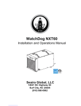
3.10 Airflowset-updata
Where ducts exceed the maximum lengths specified in the following table, the dry and wet air dampers
must be used to balance the propor tion of wet air to dry air. The correct balance is essential to maintain the
operating efficiency of the unit.
Outlet Ductdiameter Max. ductlength
Wet air 80 mm 10, 0 m
Dry air 100 mm 15, 0 m
Table 3.2 Maximum duct lengths
A
B
_
_
+
+
Figure 3.7 Dry and wet airflows/Test points position
A. D ry airflow differential pressure B. Wet airflow differential pressure
Use the built in test points to measure the pressure difference for “A” and “B” respectively, see Figure 3.7 .By
usingthegraphonpage12, the required dry airflowisacheivedatthesametimeascheckingthewetairflow.
Follow the below instructions to balance the airflows to the required amount:
1. Set the mode switch to the MAN position a nd the mains switch to the
position, the dehumidifier will
then start (see chapter 3.11, Operation).
2. Set the dry and wet air dampers t o the fully open position.
3. Adjust the dry air damper and at the same time measure the value for “A” ( using the test points). When
the value “A” c orresponds to the required dry airflow,markthevalueonthegraphinaccordancewith
the example.
4. Draw a horizontal line from value “A” to t he additional scale to the right of the graph, value “B”as
shown by the dotted line in the example.
5. Adjust the wet air dam per and at the same time measure the value for “B” (using the test points). When
the value “B” cor responds to the marked value for “B” on the graph, the wet airflow is in balance with
the dry airflow.
11 Installation 190TGB-1012-A1006

NOTE! Adjustmentsofthewetairdamper
willhaveanimpactonthedryairflow. Measureonceagainthevalue
for“A”and“B”re sp ectivelyandmake
requiredadjustmentsuntilthewetairisinbalancewiththerequireddry
airflow.
Δ
P
Δ
P
(Pa)
(Pa)
125 m /h
3
185 m /h
3
270 m /h
3
m/h
3
q
Figure 3.8 Example of r equired diff erential pressure curves.
q: Dry airflo
w(m
3
/h)
190TGB-1012-A1006 Installation 12

3.11 Operation
WARNING!
Themainscablemustbeextendedtoit’sfulllengthbeforeswitchingonthedehumidifier. Theunitmustnotbe
operatedwiththemainscablestillwrappedaroundthecablestowage.
3.11.1 Starting up
Before starting the dehumid
ifier for the first time, carry-out the following checks:
1. Check that the unit has been correctly connected to the mains supply, by reference to the identification
plate(seesection1.3, Marking ) and has been correclty connected to the supply. If a fused circuit breaker
has been fitted, check that the fuse rating in the isolator is c orrec t.
2. If a humidistat has been installed, check that it has been correctly positioned in the room and has been
properly connected to the unit (see section 3.9, Connecting the humidistat.)
3.11.2 Quick stop
Stop the unit pulling by out the plug from the wall outlet, or if it is permanently connected to the mains
supply, by operating the externally mounted circuit breaker.
3.12 Start
3.12.1 Manual o peration
1. Set the mode swi
tchtotheMAN position and the mains switch to the position
, the dehumidifier
will then star
t(seeFigure 3.9 ).
2. Allow the unit
to run for approximately 15 minutes to ensure that the operating conditions have
stabilised a
nd check that the reactivation heater is operating (heater indicator lit) and that the desiccant
rotor is rot
ating (to see the rotor rotating look through the dry out outlet).
3. Check that t
he run-time indicator is recording the unit running time.
NOTE!
Ther
un-timeindicatordoesnotstopwhentheunitisswitchedoff. Theunitmustbedisconnectedfrom
themainsC
ircuitbreakertostopthecounter.
4. Switch the mains switch to the position and check that the heater indicator goes out, and the fan has
stopped (after approx. 1 min).
3.12.2 Automatic operation
NOTE!
FortheunittooperateintheAutomaticMode,anoptionalsingle-stagehumidistatmustbeinstalledand
correctlyconnectedtotheunit.
1. Set th
emodeswitchtotheAUT position and adjust the humidistat set-point to the minimum relative
humi
dity (RH) value.
2. Set t
hemainsswitchtothe
position, the dehumidifier will then start.
3. Slo
wly increase the humidistat set-point and check that the heater indicator goes out and the fan stops
aft
er approx. 1 min (dehumidifier stops) when the set-point matches the RH in the room where the
hu
midistat is installed.
13 Installation 190TGB-1012-A1006

NOTE! Dependingonthepositionofthel
inkonthecontrolPCB,thefanmaycontuetorunwhenthereactivation
heaterhasbeenswitchedoff. Fordet
ailsseesection3.15,C ontinuousFanOperation.
4. Slowly decrease the humidistat set-point and check that the dehumidifiers switches on (heater indicator
and fan on) when the set-point value is below the RH in the room where the humidistat is installed.
Allow the unit to run for approximately 15 minutes to ensure that the operating conditions have
stabilsed.
5. Adjust the humidistat set-point to the desired RH value.
6. Switch the mains switch to the position
and check that the heater indicator goes out, and the fan has
stopped (after approx. 1 min).
A
123 4
Figure 3.9 Mod
e switch position and control panel functions.
1. Mains ON/OFF switch 2. Heater Indicator 3. Fault Indicator 4. Run-time indicator
3.13 Options
3.13.1 Remote ala rm
ARemote
alarm device can be wired directly to the control PCB (see fi gure Figure 3.10 ). The alarm output
compri
ses of a volt-free relay contact ( max. load 240 V, 10 A) which is closed when the unit has shut-down
due to t
he overtemperature cut-out operating.
3.14 Stop
Switch the units mains switch to position .
190TGB-1012-A1006 Installation 14

3.15 ContinuousFanOperation
A link on the control P CB (see see figure Figure 3.10 ) can be pre-selected to control the fan as follows:
LinkPosition Description
A Process and reactivation fans are running all the time that the unit is sw itched on. T his facility is useful fo r maintaining air
circulation du ring periods of low demand or if a pressurised environ m ent is desired to prevent uncontrolled infiltration
of hu mid air.
B Process and reactivation fans are controlled by th e humidistat and are switched on and off in conjunction with the
reactivation heater. This is the default position for the link.
Table 3.3 Continuous fan link positions
Figur e 3.10 Circuit diagram and PCB location
Link B = Normal fan operation
Link A = Continuous fan operation
15 Installation 190TGB-1012-A1006

4 Maintenance
4.1 General
The dehumidifier is designed for lo
ng, continuous operation with minimum attention. Under normal
operating conditions, requireme
nts for maintenance are minimal. Maintenance interval lengths are primarily
determined by operating condit
ions and the environment in which the unit is installed. When in doubt,
consult Munters’ product serv
ice department. See addresses for Munters r epresentatives on the back c over
of this manual.
4.2 Safety
WARNING!
Alwaysunplugthedehumidifierbeforeanymaintenanceorrepairworkiscarriedout. Incaseofafixedinstallation
wheretheplugisbeingreplacedbyacircuitbreaker,thepowermustbeswitchedoffandthecircuitbreakerlocked.
WARNING!
Adjustments,maintenanceandrepairsmustonlybecarriedoutbytrainedandqualifiedpersonnel.
WARNING!
Duetotheriskofelectricalshock,theunitmustnotbeopenedbyanyoneotherthantrainedandqualified
personnel.
190TGB-1012-A1006 Maintenance 16

4.3 Maintenanceschedule
The following maintenance schedule is recommended by Munters and covers procedures for inspection
and m aintenance as well as suggested time intervals for a unit that operates under normal operational and
environmental conditions. If the process air has a high dust content, preventative scheduled maintenance
should be performed at shor ter intervals than what is specified below.
Inspection/Maintenance
Component
3-6Months 12Months
Filter (see Figure 4.1 ). Clean the filter, retainer and housing.
Replace filter if dirty
Replace the filter. Clean the filter retainer
and housing.
Unit housing Check for physical damage and clean unit
exterior if necessary.
Check for physical damage and clean unit
exterior if necessary. If ducted, check duct
connections and test-points for signs of air
leaks and for incorrect fitting.
Humidistat N/A Check sensor f unct ion and calibrate or
replace if necessary. Contact your Munters’
product service department as required.
4.4 Filterreplacement
A
B
Figure 4.1 Filter removal
A. Plastic
screw
B. Cover
1. Unscrew the plastic screw (A) and remove the cover (B).
2. Remove the fi lter retainer from the housing.
3. Clean filter retainer and housing and replace the filter.
NOTE!
Ensurethatthefilterispositionedinfrontofthefilterretainer.
4. Remount filter retainer and cover. Tighten the plastic screw.
17 Maintenance 190TGB-1012-A1006
/