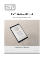
2N Telecommunications 9153102 Installation guide
- Category
- Door intercom systems
- Type
- Installation guide
This manual is also suitable for


The 2N TELEKOMUNIKACE a.s. is a Czech manufacturer and supplier of telecommunications
equipment.
The product family developed by 2N TELEKOMUNIKACE a.s. includes GSM gateways, private
branch exchanges (PBX), and door and lift communicators. 2N TELEKOMUNIKACE a.s. has
been ranked among the Czech top companies for years and represented a symbol of
stability and prosperity on the telecommunications market for almost two decades. At
present, we export our products into over 120 countries worldwide and have exclusive
distributors on all continents.
2N is a registered trademark of 2N TELEKOMUNIKACE a.s. Any product and/or other
®
names mentioned herein are registered trademarks and/or trademarks or brands protected
by law.
2N TELEKOMUNIKACE a.s. administers the FAQ database to help you quickly find
information and to answer your questions about 2N products and services. On
www.faq.2n.cz you can find information regarding products adjustment and instructions for
optimum use and procedures „What to do if...“.
2N TELEKOMUNIKACE a.s. hereby declares that the 2N product complies
®
Helios IP Uni
with all basic requirements and other relevant provisions of the 1999/5/EC directive. For
the full wording of the Declaration of Conformity see the CD-ROM enclosed or our website
at www.2n.cz.
This device complies with part 15 of the FCC Rules. Operation is subject to the following
two conditions: (1) This device may not cause harmful interference, and (2) this device
must accept any interference received, including interference that may cause undesired
operation.
The 2N TELEKOMUNIKACE a.s. is the holder of the ISO 9001:2009 certificate. All
development, production and distribution processes of the company are managed by this
standard and guarantee a high quality, technical level and professional aspect of all our
products.
Content

Content
1. Product Overview . . . . . . . . . . . . . . . . . . . . . . . . . . . . . . . . . . 4
1.1ComponentsandAssociatedProducts ...............................6
1.2TermsandSymbols ..............................................9
2. Description and Installation . . . . . . . . . . . . . . . . . . . . . . . . . . 10
2.1BeforeYouStart .................................................11
2.2MechanicalInstallation ............................................12
2.3ElectricInstallation ...............................................17
2.4ButtonTags ....................................................19
3. Function and Use . . . . . . . . . . . . . . . . . . . . . . . . . . . . . . . . . . 20
3.1Configuration ...................................................21
3.2Control ........................................................24
3.3Maintenance ....................................................25
4. Technical Parameters . . . . . . . . . . . . . . . . . . . . . . . . . . . . . . . 26
5. Supplementary Information . . . . . . . . . . . . . . . . . . . . . . . . . . 28
5.1Troubleshooting .................................................29
5.2Directives,LawsandRegulations ...................................30
5.3GeneralInstructionsandCautions ...................................32

42N TELEKOMUNIKACE a.s., www.2n.cz
®
1. Product Overview
Here is what you can find in this section:
1.1 Components and Associated Products
1.2 Terms and Symbols
Basic Features
2N
®
Helios IP Uni is a highly resistant and reliable IP door access intercom provided
with a lot of useful above-standard functions. Supporting the SIP standard and being
compatible with the leading IP PBX and telephone suppliers, can2N
®
Helios IP Uni
make use of all VoIP services. can work as a standard or2N
®
Helios IP Uni
emergency door access intercom for buildings, entrances to premises or garages,
manufacturing halls, highways and so on.
2N
®
Helios IP Uni is equipped with a loudspeaker (1 W). Thanks to an integrated
acoustic echo cancelling (AEC) system, the product provides mutual audibility even of
persons talking at the same time under normal conditions.
2N
®
Helios IP Uni can be provided with 1 or 2 pre-programmed buttons. You can set
up to three telephone numbers and time profiles for each of the buttons to increase the
accessibility of the called party.
2N
®
Helios IP Uni is equipped with an electric lock switch. You can control the switch
during a call, using any telephone set.
2N
®
Helios IP Uni is very easy to install. All you have to do is connect the system
into your LAN via a network cable and feed it from a 12 V power supply or your PoE
supporting LAN.
Configure using your PC via any web browser. Use the 2N
®
Helios IP Uni IP
to manage extensive systems easily and quickly.Manager 2N
®
Helios IP Uni

52N TELEKOMUNIKACE a.s., www.2n.cz
®
Advantages of Use
Variable mounting options (brick/plasterboard flush mounting, wall mounting)
Sensitive microphone and powerful loudspeaker
Bidirectional communication – acoustic echo cancelling
Optional dial buttons including name tags and backlight
Integrated electronic lock switches with wide setting options
LAN (PoE) or external 12 V power supply
Configuration via web interface or dedicated PC application
SIP 2.0 support
HTTP server for configuration
SNTP client for time synchronisation with server

62N TELEKOMUNIKACE a.s., www.2n.cz
®
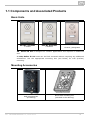
1.1 Components and Associated Products
Basic Units
9153101Part No.
1 button
9153102Part No.
2 buttons
Part. No. 9153101P
1 button, pictograms
2N
®
Helios IP Uni is designed for outdoor applications and requires no additional
roof.
All units can be flush mounted without requiring any additional2N
®
Helios IP Uni
accessories. Use the appropriate mounting box (see below) for wall (surface)
mounting.
Mounting Accessories
9153003Part No.
Wall mounting box
(Al casting)
Brick flush mounting box
(included in the delivery)

72N TELEKOMUNIKACE a.s., www.2n.cz
®
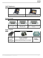
VoIP Telephones
91378351Part No.
Grandstream GXV3140 VoIP video telephone
91378354Part No.
Grandstream GXV3175 VoIP telephone
Electric Locks
932070EPart No.
BEFO 1211 12 V / 600
mA
932080EPart No.
BEFO 1221 with
momentum pin
932090EPart No.
BEFO 1211MB with mechanical
blocking
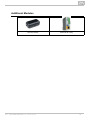
Power Supply
Part No.
91378100E
Part No.
91378100US
PoE injector
91341481EPart No.
Adapter 12 V / 2 A
A stabilised power supply has to be used if the
Ethernet (PoE) power supply is not available.
Part No.
932928E
12 V transformer


92N TELEKOMUNIKACE a.s., www.2n.cz
®
1.2 Terms and Symbols
The following symbols and pictograms are used in the manual:
Safety
abide by this information to prevent persons from injury.Always
Warning
abide by this information to prevent damage to the device.Always
Caution
Important information for system functionality.
Tip
Useful information for quick and efficient functionality.
Note
Routines or advice for efficient use of the device.


112N TELEKOMUNIKACE a.s., www.2n.cz
®
2.1 Before You Start
Product Completeness Check
Before you start please check the contents of your delivery:2N
®
Helios IP Uni
1× 2N
®
Helios IP Uni
1× Torx 10 / Torx 20 double-ended wrench
1× Installation Manual2N
®
Helios IP Uni
1× mounting template
1× A5 transparent name plate foil
1× spare name plate
1× brick flush mounting box
4× (4 × 12) mm stainless steel, torx screws for plastics
2× cable ties

122N TELEKOMUNIKACE a.s., www.2n.cz
®
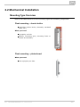
2.2 Mechanical Installation
Mounting Type Overview
Refer to the table below for a list of mounting types and necessary components.
Flush mounting – classic bricks
(including hollow bricks, thermally insulated
walls, etc.)
What you need:
A properly cut hole
Plaster, mounting glue, mounting foam or
mortar as necessary
Flush mounting – plasterboard
What you need:
Just a properly cut hole

132N TELEKOMUNIKACE a.s., www.2n.cz
®
Wall mounting
(concrete and steel structures, entry barrier
columns, etc.)
What you need:
Wall mounting box
Part No. 9153003
Common Mounting Principles
Caution
The warranty does not apply to the product defects and failures arisen as
a result of improper mounting (in contradiction herewith). The
manufacturer is neither liable for damage caused by theft within an area
that is accessible after the attached electric lock is switched. The product
is not designed as a burglar protection device except when used in
combination with a standard lock, which has the security function.
When the proper mounting instructions are not met, water might get in
and destroy the electronics. It is because the intercom circuits are under
continuous voltage and water infiltration causes an electro-chemical
reaction. The manufacturer's warranty shall be void for products damaged
in this way!
Tip
Select flush mounting where possible to make your product elegant
looking, more vandal resistant and more secure.
Caution
Stainless steel screws are used for the assembly.2N
®
Helios IP Uni
Other screws than stainless steel ones corrode soon and may aesthetically
deteriorate the surrounding environment!
Having removed the front panel, make sure that no dirt gets inside the
product (especially onto the sealing surface).

142N TELEKOMUNIKACE a.s., www.2n.cz
®
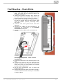
Flush Mounting – Classic Bricks
1.
2.
3.
4.
5.
6.
7.
8.
9.
10.
Cut a wall hole using the template enclosed.
Make sure that all the required cables are
available in the hole.
Unpack the plastic mounting box. Break out
the cable holes as necessary and make sure
that the wall hole is big enough for the box.
Wall up the mounting box making sure that
the box is aligned with the wall surface. Wait
until the plaster (mortar, mounting foam,
etc.) sets.
Unscrew the front panel from the door
intercom.
Connect the cables to the terminals or RJ
connector as described in the Electric
subsection.Connection
You can use the cable tie for connection as
shown:
Mounting completion – after electric
installation!
Insert the intercom in the mounting box in the
wall.
Tighten the intercom with the stainless steel
screws included in the delivery. As the screw
holes are oval, you can perfect the vertical
position before tightening.
We do not recommend you to insert the
button tags now.
Replace the stainless steel front panel fixing it
with the stainless steel screws you unscrewed
in step 4 above.

152N TELEKOMUNIKACE a.s., www.2n.cz
®
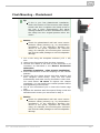
Flush Mounting – Plasterboard
1.
2.
3.
4.
5.
6.
7.
Cut a hole using the template enclosed (175 × 95)
mm.
Unscrew the front panel from the door intercom.
Connect the cables in the hole to the terminals or RJ
connector as described in the Electric Connection
.subsection
Mounting completion – after electric installation!
Insert the intercom in the hole keeping it in the vertical
position.
Loosen the four clamp screws one after another and
then retighten them slowly. They will turn aside
automatically and start moving forwards in their slots.
You need about to tighten the clamps10 turns
completely. You can perfect the vertical position before
final tightening of the screws.
We do not recommend you to insert the button tags
now.
Replace the stainless steel front panel fixing it with the
stainless steel screws you unscrewed in step 2.
Tip
If this is your first plasterboard installation,
check the function of the intercom side clamps.
Loosen and then re-tighten the clamp screw to
see how it turns automatically and starts
moving forwards in its slot. Remember to return
the clamp into the original position after the
check!
Caution
Check the plasterboard wall and room interior
pressure values (caused, e.g., by overpressure
ventilation). If the difference between the
values is too great, separate the intercom
using, for example, the mounting box enclosed
and seal the cable passage to avoid loudspeaker
damage.
Caution
Check the plasterboard wall and room interior
pressure values (caused, e.g., by overpressure
ventilation). If the difference between the
values is too great, separate the intercom
using, for example, the mounting box enclosed
and seal the cable passage to avoid loudspeaker
damage.


172N TELEKOMUNIKACE a.s., www.2n.cz
®
2.3 Electric Installation
This subsection describes how to connect into your Local Area2N
®
Helios IP Uni
Network (LAN) and how to connect supply voltage and the electric lock.
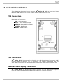
PCB Connectors
Description of Connectors
LAN – LAN connector
OUT1 – Active switched output
RELAY1 – Relay NO/NC contacts
TAMPER – Tamper switch
POWER – Power input
RESET – RESET button
LAN Connection
2N
®
Helios IP Uni is connected to the LAN via a RJ-45 terminated (connector LAN)
UTP/STP cable (of category Cat 5e or higher). The system is equipped with the
Auto-MDIX function and so both the straight and crossed cable versions can be used
External Power Supply Connection
2N
®
Helios IP Uni can be fed either from an external 12 V / 2 A DC power supply or
from the LAN equipped with the PoE 802.3af supporting network elements.

182N TELEKOMUNIKACE a.s., www.2n.cz
®
External Power Supply
An external 12 V power supply is connected to terminal block POWER. Use a 12 V ±15
% DC power source dimensioned to current intake of 2 A at least (Part No. 91341481E)
to ensure a reliable function of your device.
PoE Supply
2N
®
Helios IP Uni is compatible with the PoE 802.3af (Class 0 – 12,95 W) technology
and can be supplied directly from the LAN via compatible network elements. If your
LAN in incompatible, insert the PoE injector, Part No. , between 91378100E/US 2N
®
and the nearest network element.Helios IP Uni
Electric Lock Connection
2N
®
Helios IP Uni is equipped with an electrically isolated relay switch with NO and
NC contacts (terminal block RELAY1, up to 30 V / 1 A AC/DC) and 8 up to 12 V
DC depending on power supply (PoE: 9 V; adaptor: power supply voltage minus 2 V),
max 500 mA, switched output (terminal block OUT1), to which a standard electric lock
or another compatible electrical appliance can be connected.
Tamper Switch Connection
2N
®
Helios IP Uni is equipped with a tamper switch for detection of unauthorized
penetration into the device. After correct and complete installation of the device the
tamper switch is closed. Tamper switch opens immediately when the front panel is
removed. Tamper switch contacts are available on terminal block TAMPER SWITCH.
Device Resetting
2N
®
Helios IP Uni is equipped with a RESET button. Push the button for more than
10 s to reset the factory default values, deleting all the data stored in the device. Push
the button shortly (< 1 s) to restart the device without changing its configuration.
Note
Both outputs OUT1 and RELAY1 are switched always simultaneously.

192N TELEKOMUNIKACE a.s., www.2n.cz
®
1.
2.
2.4 Button Tags
This subsection describes work with Button Tags in .2N
®
Helios IP Uni
Tag Printing
Every delivery includes a sheet of translucent foil, which can2N
®
Helios IP Uni
be laser-printed. Cut the printed foil and insert the tags in the name plates.
Every name plate includes a piece of foil, which can be written over manually,
using a waterproof permanent marker, if necessary.
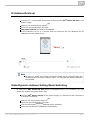
Tag Inserting/Replacing Instructions
1.
2.
3.
4.
2N
®
Helios IP Uni provides an intuitive, easy access to
the name plates. The tags are easy to insert and replace
even without a manual. You need not remove the front panel
and thus are not exposed to the risk of loss of components
while replacing the tags.
Loosen the name plate screw using the wrench
enclosed, for example. You can open the name plate
window like a door without losing the tightened screw.
Remove the used or blank name tag and insert a new
tag.
Close the name plate window and tighten the screw
appropriately.
Check the click effect of the buttons: if the button fails
to click properly when pressed (when moved by
approx. 0.5 mm), the tag is too thick or thin. Make
sure that the button clicks when you press it on either
end.
Note
Always use waterproof foil (enclosed or other) for the tags. Never use
paper or ink jet printing to avoid damage due to water leakage!

Page is loading ...
Page is loading ...
Page is loading ...
Page is loading ...
Page is loading ...
Page is loading ...
Page is loading ...
Page is loading ...
Page is loading ...
Page is loading ...
Page is loading ...
Page is loading ...
Page is loading ...
Page is loading ...
-
 1
1
-
 2
2
-
 3
3
-
 4
4
-
 5
5
-
 6
6
-
 7
7
-
 8
8
-
 9
9
-
 10
10
-
 11
11
-
 12
12
-
 13
13
-
 14
14
-
 15
15
-
 16
16
-
 17
17
-
 18
18
-
 19
19
-
 20
20
-
 21
21
-
 22
22
-
 23
23
-
 24
24
-
 25
25
-
 26
26
-
 27
27
-
 28
28
-
 29
29
-
 30
30
-
 31
31
-
 32
32
-
 33
33
-
 34
34


2N Telecommunications 9153102 Installation guide
- Category
- Door intercom systems
- Type
- Installation guide
- This manual is also suitable for
Ask a question and I''ll find the answer in the document
Finding information in a document is now easier with AI
Related papers
Other documents
-
König KN-MIC25 Datasheet
-
2N Helios IP Owner's manual
-
2N 9154100 Installation guide
-
-
-
Axis Audio 2N SIP Mic User manual
-
 Audio Solutions Helios TL64PL Assembly Instructions
-
-
 Inuktun Helios User manual
-

