
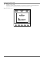
POWER AVAILABILITY
Liebert NX
™
USER MANUAL
10-20kVA
50/60Hz
400V


i
TABLE OF CONTENTS
1.0 SINGLE MODULE UPS INSTALLATION . . . . . . . . . . . . . . . . . . . . . . . . . . . . . . . . . . . . . . . . .3
1.1 Introduction . . . . . . . . . . . . . . . . . . . . . . . . . . . . . . . . . . . . . . . . . . . . . . . . . . . . . . . . . . . . . . . . 3
1.2 Preliminary Checks . . . . . . . . . . . . . . . . . . . . . . . . . . . . . . . . . . . . . . . . . . . . . . . . . . . . . . . . . . 3
1.3 Location. . . . . . . . . . . . . . . . . . . . . . . . . . . . . . . . . . . . . . . . . . . . . . . . . . . . . . . . . . . . . . . . . . . . 4
1.3.1 UPS Room . . . . . . . . . . . . . . . . . . . . . . . . . . . . . . . . . . . . . . . . . . . . . . . . . . . . . . . . . . . . . . . . . . . 4
1.3.2 External Battery Room . . . . . . . . . . . . . . . . . . . . . . . . . . . . . . . . . . . . . . . . . . . . . . . . . . . . . . . . 4
1.3.3 Storage . . . . . . . . . . . . . . . . . . . . . . . . . . . . . . . . . . . . . . . . . . . . . . . . . . . . . . . . . . . . . . . . . . . . . 4
1.4 Positioning . . . . . . . . . . . . . . . . . . . . . . . . . . . . . . . . . . . . . . . . . . . . . . . . . . . . . . . . . . . . . . . . . 5
1.4.1 System Cabinets . . . . . . . . . . . . . . . . . . . . . . . . . . . . . . . . . . . . . . . . . . . . . . . . . . . . . . . . . . . . . . 5
1.4.2 10 to 20kVA UPS . . . . . . . . . . . . . . . . . . . . . . . . . . . . . . . . . . . . . . . . . . . . . . . . . . . . . . . . . . . . . 5
1.4.3 Moving the Cabinets. . . . . . . . . . . . . . . . . . . . . . . . . . . . . . . . . . . . . . . . . . . . . . . . . . . . . . . . . . . 5
1.4.4 Clearances. . . . . . . . . . . . . . . . . . . . . . . . . . . . . . . . . . . . . . . . . . . . . . . . . . . . . . . . . . . . . . . . . . . 6
1.4.5 Access . . . . . . . . . . . . . . . . . . . . . . . . . . . . . . . . . . . . . . . . . . . . . . . . . . . . . . . . . . . . . . . . . . . . . . 6
1.4.6 Final Positioning. . . . . . . . . . . . . . . . . . . . . . . . . . . . . . . . . . . . . . . . . . . . . . . . . . . . . . . . . . . . . . 6
1.4.7 Floor Anchoring . . . . . . . . . . . . . . . . . . . . . . . . . . . . . . . . . . . . . . . . . . . . . . . . . . . . . . . . . . . . . . 6
1.4.8 Cable Entry . . . . . . . . . . . . . . . . . . . . . . . . . . . . . . . . . . . . . . . . . . . . . . . . . . . . . . . . . . . . . . . . . . 6
1.5 External Protective Devices. . . . . . . . . . . . . . . . . . . . . . . . . . . . . . . . . . . . . . . . . . . . . . . . . . . . 6
1.5.1 Rectifier and Bypass Input . . . . . . . . . . . . . . . . . . . . . . . . . . . . . . . . . . . . . . . . . . . . . . . . . . . . . 6
1.5.2 External Battery. . . . . . . . . . . . . . . . . . . . . . . . . . . . . . . . . . . . . . . . . . . . . . . . . . . . . . . . . . . . . . 7
1.5.3 UPS Output . . . . . . . . . . . . . . . . . . . . . . . . . . . . . . . . . . . . . . . . . . . . . . . . . . . . . . . . . . . . . . . . . 7
1.6 Power Cables . . . . . . . . . . . . . . . . . . . . . . . . . . . . . . . . . . . . . . . . . . . . . . . . . . . . . . . . . . . . . . . 7
1.6.1 Cable Termination . . . . . . . . . . . . . . . . . . . . . . . . . . . . . . . . . . . . . . . . . . . . . . . . . . . . . . . . . . . . 9
1.7 Control Cables and Communication . . . . . . . . . . . . . . . . . . . . . . . . . . . . . . . . . . . . . . . . . . . . 11
1.7.1 Monitor Board Features . . . . . . . . . . . . . . . . . . . . . . . . . . . . . . . . . . . . . . . . . . . . . . . . . . . . . . . 11
1.8 Dry Contacts . . . . . . . . . . . . . . . . . . . . . . . . . . . . . . . . . . . . . . . . . . . . . . . . . . . . . . . . . . . . . . . 12
1.8.1 Input Dry Contacts. . . . . . . . . . . . . . . . . . . . . . . . . . . . . . . . . . . . . . . . . . . . . . . . . . . . . . . . . . . 12
1.8.2 Maintenance Bypass Cabinet Interface . . . . . . . . . . . . . . . . . . . . . . . . . . . . . . . . . . . . . . . . . . 12
1.8.3 External Circuit-Breaker Interface . . . . . . . . . . . . . . . . . . . . . . . . . . . . . . . . . . . . . . . . . . . . . . 13
1.8.4 Output Dry Contacts . . . . . . . . . . . . . . . . . . . . . . . . . . . . . . . . . . . . . . . . . . . . . . . . . . . . . . . . . 13
1.8.5 Emergency Power Off Input. . . . . . . . . . . . . . . . . . . . . . . . . . . . . . . . . . . . . . . . . . . . . . . . . . . . 14
1.8.6 External Bypass Switch Interlock . . . . . . . . . . . . . . . . . . . . . . . . . . . . . . . . . . . . . . . . . . . . . . . 16
1.8.7 Battery Start Facility . . . . . . . . . . . . . . . . . . . . . . . . . . . . . . . . . . . . . . . . . . . . . . . . . . . . . . . . . 16
2.0 BATTERY INSTALLATION . . . . . . . . . . . . . . . . . . . . . . . . . . . . . . . . . . . . . . . . . . . . . . . . . .17
2.1 Introduction . . . . . . . . . . . . . . . . . . . . . . . . . . . . . . . . . . . . . . . . . . . . . . . . . . . . . . . . . . . . . . . 17
2.2 Safety . . . . . . . . . . . . . . . . . . . . . . . . . . . . . . . . . . . . . . . . . . . . . . . . . . . . . . . . . . . . . . . . . . . . 18
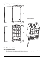
2.3 Battery Cabinet . . . . . . . . . . . . . . . . . . . . . . . . . . . . . . . . . . . . . . . . . . . . . . . . . . . . . . . . . . . . 19
2.3.1 Introduction . . . . . . . . . . . . . . . . . . . . . . . . . . . . . . . . . . . . . . . . . . . . . . . . . . . . . . . . . . . . . . . . 19
2.3.2 Temperature Considerations . . . . . . . . . . . . . . . . . . . . . . . . . . . . . . . . . . . . . . . . . . . . . . . . . . . 19
2.3.3 Dimensions . . . . . . . . . . . . . . . . . . . . . . . . . . . . . . . . . . . . . . . . . . . . . . . . . . . . . . . . . . . . . . . . . 19
2.3.4 Weight . . . . . . . . . . . . . . . . . . . . . . . . . . . . . . . . . . . . . . . . . . . . . . . . . . . . . . . . . . . . . . . . . . . . 19
2.3.5 Circuit Isolator Features . . . . . . . . . . . . . . . . . . . . . . . . . . . . . . . . . . . . . . . . . . . . . . . . . . . . . . 19
2.3.6 Battery Temperature Board (Optional). . . . . . . . . . . . . . . . . . . . . . . . . . . . . . . . . . . . . . . . . . . 20
2.3.7 Moving the Battery Cabinets. . . . . . . . . . . . . . . . . . . . . . . . . . . . . . . . . . . . . . . . . . . . . . . . . . . 20
2.3.8 Cable Entry . . . . . . . . . . . . . . . . . . . . . . . . . . . . . . . . . . . . . . . . . . . . . . . . . . . . . . . . . . . . . . . . . 20
2.3.9 General Arrangement Drawings . . . . . . . . . . . . . . . . . . . . . . . . . . . . . . . . . . . . . . . . . . . . . . . . 21

ii
2.4 Battery Power Cables. . . . . . . . . . . . . . . . . . . . . . . . . . . . . . . . . . . . . . . . . . . . . . . . . . . . . . . . 22
2.4.1 Connection Principles. . . . . . . . . . . . . . . . . . . . . . . . . . . . . . . . . . . . . . . . . . . . . . . . . . . . . . . . . 22
2.4.2 Fitting the Batteries. . . . . . . . . . . . . . . . . . . . . . . . . . . . . . . . . . . . . . . . . . . . . . . . . . . . . . . . . . 23
2.4.3 Connecting the Battery . . . . . . . . . . . . . . . . . . . . . . . . . . . . . . . . . . . . . . . . . . . . . . . . . . . . . . . 23
2.4.4 Battery Room Design . . . . . . . . . . . . . . . . . . . . . . . . . . . . . . . . . . . . . . . . . . . . . . . . . . . . . . . . . 23
2.5 Battery Control. . . . . . . . . . . . . . . . . . . . . . . . . . . . . . . . . . . . . . . . . . . . . . . . . . . . . . . . . . . . . 23
3.0 UPS MULTI-MODULE INSTALLATION . . . . . . . . . . . . . . . . . . . . . . . . . . . . . . . . . . . . . . . . .24
3.1 General . . . . . . . . . . . . . . . . . . . . . . . . . . . . . . . . . . . . . . . . . . . . . . . . . . . . . . . . . . . . . . . . . . . 24
3.2 Paralleled UPS Modules . . . . . . . . . . . . . . . . . . . . . . . . . . . . . . . . . . . . . . . . . . . . . . . . . . . . . 25
3.2.1 Cabinet Installation . . . . . . . . . . . . . . . . . . . . . . . . . . . . . . . . . . . . . . . . . . . . . . . . . . . . . . . . . . 25
3.2.2 External Protective Devices . . . . . . . . . . . . . . . . . . . . . . . . . . . . . . . . . . . . . . . . . . . . . . . . . . . . 26
3.2.3 Power Cables. . . . . . . . . . . . . . . . . . . . . . . . . . . . . . . . . . . . . . . . . . . . . . . . . . . . . . . . . . . . . . . . 26
3.2.4 Control Cables . . . . . . . . . . . . . . . . . . . . . . . . . . . . . . . . . . . . . . . . . . . . . . . . . . . . . . . . . . . . . . 27
3.3 Hot-Standby UPS Modules . . . . . . . . . . . . . . . . . . . . . . . . . . . . . . . . . . . . . . . . . . . . . . . . . . . 27
3.3.1 Cabinet Installation . . . . . . . . . . . . . . . . . . . . . . . . . . . . . . . . . . . . . . . . . . . . . . . . . . . . . . . . . . 27
3.3.2 External Protective Devices . . . . . . . . . . . . . . . . . . . . . . . . . . . . . . . . . . . . . . . . . . . . . . . . . . . . 27
3.3.3 Power Cables. . . . . . . . . . . . . . . . . . . . . . . . . . . . . . . . . . . . . . . . . . . . . . . . . . . . . . . . . . . . . . . . 28
3.4 Dual Bus System . . . . . . . . . . . . . . . . . . . . . . . . . . . . . . . . . . . . . . . . . . . . . . . . . . . . . . . . . . . 28
3.4.1 Cabinet Installation . . . . . . . . . . . . . . . . . . . . . . . . . . . . . . . . . . . . . . . . . . . . . . . . . . . . . . . . . . 28
3.4.2 External Protective Devices . . . . . . . . . . . . . . . . . . . . . . . . . . . . . . . . . . . . . . . . . . . . . . . . . . . . 29
3.4.3 Power Cables. . . . . . . . . . . . . . . . . . . . . . . . . . . . . . . . . . . . . . . . . . . . . . . . . . . . . . . . . . . . . . . . 29
3.4.4 Control Wires . . . . . . . . . . . . . . . . . . . . . . . . . . . . . . . . . . . . . . . . . . . . . . . . . . . . . . . . . . . . . . . 30
3.4.5 Extended Dual Bus Synchronization Option (DBS Interface Box) . . . . . . . . . . . . . . . . . . . . . 30
4.0 INSTALLATION DRAWINGS. . . . . . . . . . . . . . . . . . . . . . . . . . . . . . . . . . . . . . . . . . . . . . . . .31
5.0 OPERATION . . . . . . . . . . . . . . . . . . . . . . . . . . . . . . . . . . . . . . . . . . . . . . . . . . . . . . . . . . .36
5.1 Introduction . . . . . . . . . . . . . . . . . . . . . . . . . . . . . . . . . . . . . . . . . . . . . . . . . . . . . . . . . . . . . . . 36
5.1.1 Split-Bypass Input . . . . . . . . . . . . . . . . . . . . . . . . . . . . . . . . . . . . . . . . . . . . . . . . . . . . . . . . . . . 36
5.1.2 Static Transfer Switch . . . . . . . . . . . . . . . . . . . . . . . . . . . . . . . . . . . . . . . . . . . . . . . . . . . . . . . . 37
5.1.3 Battery Temperature Compensation. . . . . . . . . . . . . . . . . . . . . . . . . . . . . . . . . . . . . . . . . . . . . 37
5.1.4 Redundant Control Power Supply Board . . . . . . . . . . . . . . . . . . . . . . . . . . . . . . . . . . . . . . . . . 38
5.1.5 Socket Outlet . . . . . . . . . . . . . . . . . . . . . . . . . . . . . . . . . . . . . . . . . . . . . . . . . . . . . . . . . . . . . . . 38
5.2 Multi Module UPS—1+N . . . . . . . . . . . . . . . . . . . . . . . . . . . . . . . . . . . . . . . . . . . . . . . . . . . . . 38
5.2.1 Features of NX Multi-Module UPS Configurations . . . . . . . . . . . . . . . . . . . . . . . . . . . . . . . . . 39
5.2.2 Requirements for Paralleling of UPS Modules . . . . . . . . . . . . . . . . . . . . . . . . . . . . . . . . . . . . . 39
5.3 Modes of Operation. . . . . . . . . . . . . . . . . . . . . . . . . . . . . . . . . . . . . . . . . . . . . . . . . . . . . . . . . . 39
5.3.1 Normal Mode . . . . . . . . . . . . . . . . . . . . . . . . . . . . . . . . . . . . . . . . . . . . . . . . . . . . . . . . . . . . . . . 39
5.3.2 Battery Mode (Stored Energy Mode) . . . . . . . . . . . . . . . . . . . . . . . . . . . . . . . . . . . . . . . . . . . . . 39
5.3.3 Auto-Restart Mode . . . . . . . . . . . . . . . . . . . . . . . . . . . . . . . . . . . . . . . . . . . . . . . . . . . . . . . . . . . 39
5.3.4 Bypass Mode . . . . . . . . . . . . . . . . . . . . . . . . . . . . . . . . . . . . . . . . . . . . . . . . . . . . . . . . . . . . . . . . 40
5.3.5 Maintenance Mode (Manual Bypass) . . . . . . . . . . . . . . . . . . . . . . . . . . . . . . . . . . . . . . . . . . . . 40
5.3.6 ECO Mode (Single UPS Only) . . . . . . . . . . . . . . . . . . . . . . . . . . . . . . . . . . . . . . . . . . . . . . . . . . 40
5.3.7 Parallel Redundancy Mode (System Expansion) . . . . . . . . . . . . . . . . . . . . . . . . . . . . . . . . . . . 40
5.3.8 Hot-Standby Mode . . . . . . . . . . . . . . . . . . . . . . . . . . . . . . . . . . . . . . . . . . . . . . . . . . . . . . . . . . . 40
5.3.9 Frequency Converter Mode . . . . . . . . . . . . . . . . . . . . . . . . . . . . . . . . . . . . . . . . . . . . . . . . . . . . 40
5.4 Battery Management—Set During Commissioning. . . . . . . . . . . . . . . . . . . . . . . . . . . . . . . . 41
5.4.1 Normal Function. . . . . . . . . . . . . . . . . . . . . . . . . . . . . . . . . . . . . . . . . . . . . . . . . . . . . . . . . . . . . 41

iii
5.4.2 Advanced Functions (Software Settings Performed by the Commissioning Engineer) . . . . . 41
5.5 Battery Protection (settings by commissioning engineer) . . . . . . . . . . . . . . . . . . . . . . . . . . . 41
6.0 OPERATING PROCEDURES . . . . . . . . . . . . . . . . . . . . . . . . . . . . . . . . . . . . . . . . . . . . . . . .42
6.1 Introduction . . . . . . . . . . . . . . . . . . . . . . . . . . . . . . . . . . . . . . . . . . . . . . . . . . . . . . . . . . . . . . . 42
6.1.1 Power Switches . . . . . . . . . . . . . . . . . . . . . . . . . . . . . . . . . . . . . . . . . . . . . . . . . . . . . . . . . . . . . . 42
6.2 UPS Startup . . . . . . . . . . . . . . . . . . . . . . . . . . . . . . . . . . . . . . . . . . . . . . . . . . . . . . . . . . . . . . . 43
6.2.1 Start-Up Procedure . . . . . . . . . . . . . . . . . . . . . . . . . . . . . . . . . . . . . . . . . . . . . . . . . . . . . . . . . . 43
6.2.2 Verify Switching Between Operation Modes . . . . . . . . . . . . . . . . . . . . . . . . . . . . . . . . . . . . . . 44
6.3 Switching the UPS from Normal to Maintenance Bypass . . . . . . . . . . . . . . . . . . . . . . . . . . . 45
6.4 Powering Down the UPS . . . . . . . . . . . . . . . . . . . . . . . . . . . . . . . . . . . . . . . . . . . . . . . . . . . . . 45
6.5 Powering Down the UPS and Maintaining Power to Load . . . . . . . . . . . . . . . . . . . . . . . . . . 46
6.6 Emergency Shutdown With EPO . . . . . . . . . . . . . . . . . . . . . . . . . . . . . . . . . . . . . . . . . . . . . . 47
6.7 Auto Restart . . . . . . . . . . . . . . . . . . . . . . . . . . . . . . . . . . . . . . . . . . . . . . . . . . . . . . . . . . . . . . . 47
6.8 Reset After Shutdown for Emergency Stop (EPO Action) or Other Conditions . . . . . . . . . . 47
6.9 Language Selection . . . . . . . . . . . . . . . . . . . . . . . . . . . . . . . . . . . . . . . . . . . . . . . . . . . . . . . . . 47
6.10 Changing the Current Date and Time . . . . . . . . . . . . . . . . . . . . . . . . . . . . . . . . . . . . . . . . . . 48
6.11 Command Password . . . . . . . . . . . . . . . . . . . . . . . . . . . . . . . . . . . . . . . . . . . . . . . . . . . . . . . . . 48
7.0 OPERATOR CONTROL PANEL AND DISPLAY . . . . . . . . . . . . . . . . . . . . . . . . . . . . . . . . . . .49
7.1 Introduction . . . . . . . . . . . . . . . . . . . . . . . . . . . . . . . . . . . . . . . . . . . . . . . . . . . . . . . . . . . . . . . 49
7.1.1 Mimic Power Flow . . . . . . . . . . . . . . . . . . . . . . . . . . . . . . . . . . . . . . . . . . . . . . . . . . . . . . . . . . . 50
7.1.2 Audible Alarm (Buzzer) . . . . . . . . . . . . . . . . . . . . . . . . . . . . . . . . . . . . . . . . . . . . . . . . . . . . . . . 50
7.1.3 Direct Access Push Buttons (Keys) . . . . . . . . . . . . . . . . . . . . . . . . . . . . . . . . . . . . . . . . . . . . . . 51
7.1.4 LCD Monitor and Menu keys. . . . . . . . . . . . . . . . . . . . . . . . . . . . . . . . . . . . . . . . . . . . . . . . . . . 51
7.1.5 Detailed Description of Menu Items . . . . . . . . . . . . . . . . . . . . . . . . . . . . . . . . . . . . . . . . . . . . . 53
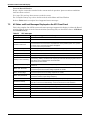
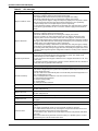
7.2 All Status and Event Messages Displayed on the UPS Front Panel. . . . . . . . . . . . . . . . . . . 55
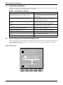
7.3 Prompt (Pop-Up) Windows. . . . . . . . . . . . . . . . . . . . . . . . . . . . . . . . . . . . . . . . . . . . . . . . . . . . 59
7.4 Dynamic Energy Flow Chart and UPS Help Screen . . . . . . . . . . . . . . . . . . . . . . . . . . . . . . . 59
7.5 Default Screen Saver . . . . . . . . . . . . . . . . . . . . . . . . . . . . . . . . . . . . . . . . . . . . . . . . . . . . . . . . 60
8.0 OPTIONS—FOR ASSEMBLY INSIDE THE UPS CABINET . . . . . . . . . . . . . . . . . . . . . . . . . . .61
8.1 Protection . . . . . . . . . . . . . . . . . . . . . . . . . . . . . . . . . . . . . . . . . . . . . . . . . . . . . . . . . . . . . . . . . 61
8.1.1 Battery Ground Fault Detection . . . . . . . . . . . . . . . . . . . . . . . . . . . . . . . . . . . . . . . . . . . . . . . . 61
8.1.2 Redundant Fan for Power Module. . . . . . . . . . . . . . . . . . . . . . . . . . . . . . . . . . . . . . . . . . . . . . . 62
8.1.3 OC Web Card - SNMP/HTTP Network Interface Card . . . . . . . . . . . . . . . . . . . . . . . . . . . . . . 63
8.1.4 Relay Card . . . . . . . . . . . . . . . . . . . . . . . . . . . . . . . . . . . . . . . . . . . . . . . . . . . . . . . . . . . . . . . . . 64
8.1.5 Multiport-4 Card. . . . . . . . . . . . . . . . . . . . . . . . . . . . . . . . . . . . . . . . . . . . . . . . . . . . . . . . . . . . . 64
8.2 OC485 Web Card – Modbus, Jbus, IGM Net . . . . . . . . . . . . . . . . . . . . . . . . . . . . . . . . . . . . . 66
8.2.1 Remote Alarm Monitor. . . . . . . . . . . . . . . . . . . . . . . . . . . . . . . . . . . . . . . . . . . . . . . . . . . . . . . . 66
9.0 TECHNICAL SPECIFICATIONS . . . . . . . . . . . . . . . . . . . . . . . . . . . . . . . . . . . . . . . . . . . . . . .67
9.1 Conformity and Standards. . . . . . . . . . . . . . . . . . . . . . . . . . . . . . . . . . . . . . . . . . . . . . . . . . . . 67

iv
FIGURES
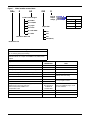
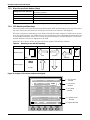
Figure i Model number nomenclature . . . . . . . . . . . . . . . . . . . . . . . . . . . . . . . . . . . . . . . . . . . . . . . . . . . . . . . vi
Figure 1 Residual current circuit breakers (RCCB) symbols . . . . . . . . . . . . . . . . . . . . . . . . . . . . . . . . . . . . . 7
Figure 2 Auxiliary terminal block detail . . . . . . . . . . . . . . . . . . . . . . . . . . . . . . . . . . . . . . . . . . . . . . . . . . . . 11
Figure 3 Input dry contacts . . . . . . . . . . . . . . . . . . . . . . . . . . . . . . . . . . . . . . . . . . . . . . . . . . . . . . . . . . . . . . . 12
Figure 4 Output dry contacts and EPO wiring . . . . . . . . . . . . . . . . . . . . . . . . . . . . . . . . . . . . . . . . . . . . . . . 13
Figure 5 Battery start for UPS . . . . . . . . . . . . . . . . . . . . . . . . . . . . . . . . . . . . . . . . . . . . . . . . . . . . . . . . . . . . 16
Figure 6 Single temperature sensor and monitor board-U2 . . . . . . . . . . . . . . . . . . . . . . . . . . . . . . . . . . . . . 20
Figure 7 Battery cabinet bottom cable entry location . . . . . . . . . . . . . . . . . . . . . . . . . . . . . . . . . . . . . . . . . . 21
Figure 8 Battery cabinet with fuse or optional circuit breaker locations . . . . . . . . . . . . . . . . . . . . . . . . . . . 22
Figure 9 Battery room design . . . . . . . . . . . . . . . . . . . . . . . . . . . . . . . . . . . . . . . . . . . . . . . . . . . . . . . . . . . . . 23
Figure 10 Emergency power off connections . . . . . . . . . . . . . . . . . . . . . . . . . . . . . . . . . . . . . . . . . . . . . . . . . . 24
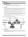
Figure 11 Typical 1+N system block diagram with common input supply, with separate batteries
and optional output / bypass distribution panel . . . . . . . . . . . . . . . . . . . . . . . . . . . . . . . . . . . . . . . 25
Figure 12 Dry contacts, multiple UPS modules with distribution panel . . . . . . . . . . . . . . . . . . . . . . . . . . . . 26
Figure 13 Connection of 1+N system parallel control cables. . . . . . . . . . . . . . . . . . . . . . . . . . . . . . . . . . . . . . 27
Figure 14 Hot standby configuration . . . . . . . . . . . . . . . . . . . . . . . . . . . . . . . . . . . . . . . . . . . . . . . . . . . . . . . . 28
Figure 15 Typical dual bus system configuration with static transfer switch and Load Bus Synch . . . . . . 29
Figure 16 Connections of a typical dual bus system utilising Load Bus Synch . . . . . . . . . . . . . . . . . . . . . . . 30
Figure 17 Electrical connections . . . . . . . . . . . . . . . . . . . . . . . . . . . . . . . . . . . . . . . . . . . . . . . . . . . . . . . . . . . . 31
Figure 18 General arrangement—10-20kVA UPS module . . . . . . . . . . . . . . . . . . . . . . . . . . . . . . . . . . . . . . . 32
Figure 19 10-20kVA NX front view with doors open . . . . . . . . . . . . . . . . . . . . . . . . . . . . . . . . . . . . . . . . . . . . 33
Figure 20 Location of parallel logic board M3 . . . . . . . . . . . . . . . . . . . . . . . . . . . . . . . . . . . . . . . . . . . . . . . . . 34
Figure 21 Internal battery layout and connecting . . . . . . . . . . . . . . . . . . . . . . . . . . . . . . . . . . . . . . . . . . . . . . 34
Figure 22 Internal battery layout . . . . . . . . . . . . . . . . . . . . . . . . . . . . . . . . . . . . . . . . . . . . . . . . . . . . . . . . . . . 35
Figure 23 Single unit block diagram with split-bypass input . . . . . . . . . . . . . . . . . . . . . . . . . . . . . . . . . . . . . 36
Figure 24 Multiple battery temperature sensors . . . . . . . . . . . . . . . . . . . . . . . . . . . . . . . . . . . . . . . . . . . . . . . 37
Figure 25 1+N multi-module UPS with external maintenance bypass switch . . . . . . . . . . . . . . . . . . . . . . . 38
Figure 26 Example of configuration for single UPS with external maintenance bypass cabinet. . . . . . . . . 46
Figure 27 UPS control and display panel . . . . . . . . . . . . . . . . . . . . . . . . . . . . . . . . . . . . . . . . . . . . . . . . . . . . . 49
Figure 28 Graphic LCD monitor windows and keypad . . . . . . . . . . . . . . . . . . . . . . . . . . . . . . . . . . . . . . . . . . 51
Figure 29 Menu tree . . . . . . . . . . . . . . . . . . . . . . . . . . . . . . . . . . . . . . . . . . . . . . . . . . . . . . . . . . . . . . . . . . . . . 52
Figure 30 Help screen . . . . . . . . . . . . . . . . . . . . . . . . . . . . . . . . . . . . . . . . . . . . . . . . . . . . . . . . . . . . . . . . . . . . 59
Figure 31 Default screen . . . . . . . . . . . . . . . . . . . . . . . . . . . . . . . . . . . . . . . . . . . . . . . . . . . . . . . . . . . . . . . . . . 60
Figure 32 Battery ground fault detection set connections. . . . . . . . . . . . . . . . . . . . . . . . . . . . . . . . . . . . . . . . 61
Figure 33 Redundant power module fan set. . . . . . . . . . . . . . . . . . . . . . . . . . . . . . . . . . . . . . . . . . . . . . . . . . . 62
Figure 34 Communication bays and cable location . . . . . . . . . . . . . . . . . . . . . . . . . . . . . . . . . . . . . . . . . . . . . 62
Figure 35 OC Web Card data summary window . . . . . . . . . . . . . . . . . . . . . . . . . . . . . . . . . . . . . . . . . . . . . . . 63
Figure 36 OC Web Card battery data summary . . . . . . . . . . . . . . . . . . . . . . . . . . . . . . . . . . . . . . . . . . . . . . . 63
Figure 37 SiteNet MultiPort4 Intellislot pin configuration. . . . . . . . . . . . . . . . . . . . . . . . . . . . . . . . . . . . . . . 65
Figure 38 OC485 Web card . . . . . . . . . . . . . . . . . . . . . . . . . . . . . . . . . . . . . . . . . . . . . . . . . . . . . . . . . . . . . . . . 66

v
TABLES
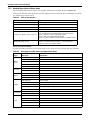
Table 1 Distance from floor to connection point on the equipment . . . . . . . . . . . . . . . . . . . . . . . . . . . . . . . . 8
Table 2 Maximum steady state AC and DC currents. . . . . . . . . . . . . . . . . . . . . . . . . . . . . . . . . . . . . . . . . . . 8
Table 3 Input dry contacts at X3 . . . . . . . . . . . . . . . . . . . . . . . . . . . . . . . . . . . . . . . . . . . . . . . . . . . . . . . . . . 12
Table 4 Maintenance bypass cabinet interface. . . . . . . . . . . . . . . . . . . . . . . . . . . . . . . . . . . . . . . . . . . . . . . 12
Table 5 External circuit-breaker interface . . . . . . . . . . . . . . . . . . . . . . . . . . . . . . . . . . . . . . . . . . . . . . . . . . 13
Table 6 Output dry contact relays . . . . . . . . . . . . . . . . . . . . . . . . . . . . . . . . . . . . . . . . . . . . . . . . . . . . . . . . . 13
Table 7 EPO input contact relays . . . . . . . . . . . . . . . . . . . . . . . . . . . . . . . . . . . . . . . . . . . . . . . . . . . . . . . . . 14
Table 8 Input dry contact relays . . . . . . . . . . . . . . . . . . . . . . . . . . . . . . . . . . . . . . . . . . . . . . . . . . . . . . . . . . 14
Table 9 Dimensions and weight. . . . . . . . . . . . . . . . . . . . . . . . . . . . . . . . . . . . . . . . . . . . . . . . . . . . . . . . . . . 19
Table 10 UPS operating modes . . . . . . . . . . . . . . . . . . . . . . . . . . . . . . . . . . . . . . . . . . . . . . . . . . . . . . . . . . . . 42
Table 11 Rotary switch configurations. . . . . . . . . . . . . . . . . . . . . . . . . . . . . . . . . . . . . . . . . . . . . . . . . . . . . . 42
Table 12 UPS control and display panel components . . . . . . . . . . . . . . . . . . . . . . . . . . . . . . . . . . . . . . . . . . 49
Table 13 Rectifier indicator—1 . . . . . . . . . . . . . . . . . . . . . . . . . . . . . . . . . . . . . . . . . . . . . . . . . . . . . . . . . . . . 50
Table 14 Battery indicator—2 . . . . . . . . . . . . . . . . . . . . . . . . . . . . . . . . . . . . . . . . . . . . . . . . . . . . . . . . . . . . . 50
Table 15 Bypass indicator—3 . . . . . . . . . . . . . . . . . . . . . . . . . . . . . . . . . . . . . . . . . . . . . . . . . . . . . . . . . . . . . 50
Table 16 Inverter indicator—4 . . . . . . . . . . . . . . . . . . . . . . . . . . . . . . . . . . . . . . . . . . . . . . . . . . . . . . . . . . . . 50
Table 17 Load indicator—5 . . . . . . . . . . . . . . . . . . . . . . . . . . . . . . . . . . . . . . . . . . . . . . . . . . . . . . . . . . . . . . . 50
Table 18 Status (Alarm) indicator—6 . . . . . . . . . . . . . . . . . . . . . . . . . . . . . . . . . . . . . . . . . . . . . . . . . . . . . . . 50
Table 19 Audible alarm key . . . . . . . . . . . . . . . . . . . . . . . . . . . . . . . . . . . . . . . . . . . . . . . . . . . . . . . . . . . . . . . 50
Table 20 Menu key Icons and their meaning . . . . . . . . . . . . . . . . . . . . . . . . . . . . . . . . . . . . . . . . . . . . . . . . . 51
Table 21 UPS system window . . . . . . . . . . . . . . . . . . . . . . . . . . . . . . . . . . . . . . . . . . . . . . . . . . . . . . . . . . . . . 53
Table 22 Descriptions of UPS menus and data window items . . . . . . . . . . . . . . . . . . . . . . . . . . . . . . . . . . . 53
Table 23 UPS messages . . . . . . . . . . . . . . . . . . . . . . . . . . . . . . . . . . . . . . . . . . . . . . . . . . . . . . . . . . . . . . . . . 55
Table 24 Prompt windows, meanings . . . . . . . . . . . . . . . . . . . . . . . . . . . . . . . . . . . . . . . . . . . . . . . . . . . . . . . 59
Table 25 Dry contact fault alarm signal is available for remote monitoring . . . . . . . . . . . . . . . . . . . . . . . . 61
Table 26 Relay Card pin configuration . . . . . . . . . . . . . . . . . . . . . . . . . . . . . . . . . . . . . . . . . . . . . . . . . . . . . . 64
Table 27 SiteNet MultiPort4 Intellislot pin assignment . . . . . . . . . . . . . . . . . . . . . . . . . . . . . . . . . . . . . . . . 65
Table 28 NX communication options. . . . . . . . . . . . . . . . . . . . . . . . . . . . . . . . . . . . . . . . . . . . . . . . . . . . . . . . 66
Table 29 Compliance with European, international standards. . . . . . . . . . . . . . . . . . . . . . . . . . . . . . . . . . . 67
Table 30 Environmental characteristics . . . . . . . . . . . . . . . . . . . . . . . . . . . . . . . . . . . . . . . . . . . . . . . . . . . . . 67
Table 31 Overall efficiency, heat losses and air exchange . . . . . . . . . . . . . . . . . . . . . . . . . . . . . . . . . . . . . . . 67
Table 32 Mechanical characteristics . . . . . . . . . . . . . . . . . . . . . . . . . . . . . . . . . . . . . . . . . . . . . . . . . . . . . . . . 68
Table 33 Rectifier AC input (mains) . . . . . . . . . . . . . . . . . . . . . . . . . . . . . . . . . . . . . . . . . . . . . . . . . . . . . . . . 68
Table 34 Inverter output to critical load . . . . . . . . . . . . . . . . . . . . . . . . . . . . . . . . . . . . . . . . . . . . . . . . . . . . . 69
Table 35 Battery . . . . . . . . . . . . . . . . . . . . . . . . . . . . . . . . . . . . . . . . . . . . . . . . . . . . . . . . . . . . . . . . . . . . . . . . 69
Table 36 Bypass mains input. . . . . . . . . . . . . . . . . . . . . . . . . . . . . . . . . . . . . . . . . . . . . . . . . . .
. . . . . . . . . . . 70

vi
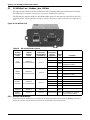
Figure i Model number nomenclature
UPS Single Module
Liebert NXe UPS module ratings:
10, 15, 20kVA (with internal battery)
Example:
NXE0A0010U =
10kVA module for Europe and Middle East, 400V/230V
output
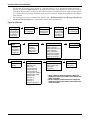
Options Model
Identification Note
Battery cabinet NXE0NBCS
Battery Ground Fault detection kit NXA0UFXBGF
Battery temperature probe (for external battery) NXA0UFXBTS
Maintenance bypass cabinet (separate bypass input) NXE0NMBX Specify total system kVA
Fan Redundancy kit NXE0UFXRF
Specify UPS kVA rating
Seismic Anchor kit NXA0UFXSAN
Dual bus control cable 05-10-15 metres NXA0UFXD
Specify length in metres
Parallel control cable kit 05-10-15 metres NXA0UFXP
Relay Card (On Bat, Bat Low, On Byp, Sum, UPS Fail)
MultiPort4 (4 sets On Bat, bat Low)
Web browser/TCPIP/SNMP Card
Jbus/Modbus Card
RELAYCARD-INT
MULTIPORT 4
OCWEB-LB
OC485CARD
These are Intellislot plug-in cards
(3 slots available).
RAM - Remote Alarm Monitor NXA0CFXRAM Requires RELAYCARD-INT
Modem card NXA0CFXMOD
Extended LBS box NXA0UFXLBS
NXe U
NX Product Line
Revision to Base Unit
Feature Set for Region
A0 - EMEA
B0 - Aust/NZ
C0 - Japan
D0 - China
E0 - Latin Amer
F0 - Other
Input &
Output
Voltage
50/60Hz
Voltage Code
220/380 F
230/400 U
240/415 G
0A0010
Output kVA
010
015
020
030 (future)

1
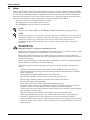
SAFETY PRECAUTIONS
This manual contains information concerning the installation and operation of this Emerson Network
Power Liebert NX Uninterruptible Power System (UPS).
This manual should be read before commencing installation.
The UPS must be commissioned and serviced by an engineer approved by the manufacturer (or
agent).
Failure to do so could result in personnel safety risk, equipment malfunction and invalidation of war-
ranty.
The Liebert NX has been designed for Commercial/Industrial use only, and is not recommended for
use in life support applications.
This is a low emission CLASS A Uninterruptible Power System (UPS) product. In a residential envi-
ronment, this product may nevertheless cause radio interference, in which case, the user may be
required to take additional measures.
Conformity and Standards
This equipment complies with CE directives 73/23 & 93/68 (LV Safety) and 89/336 (EMC), with Aus-
tralia and New Zealand EMC Framework (C-Tick) and with the following product standards for Unin-
terruptible Power System (UPS).
• EN / IEC / AS 62040-1-1—General and safety requirements for use in operator access area
• EN / IEC / AS 62040-2—EMC requirements; Class A compliant
• EN / IEC / AS 62040-3—Performance requirements and test methods
For more details, see 9.0 - Technical Specifications
Continued compliance requires installation in accordance with these instructions and the use of man-
ufacturer approved accessories only.
!
WARNING
High Leakage Current
EARTH CONNECTION IS ESSENTIAL BEFORE CONNECTING THE INPUT SUPPLY.
Earth leakage current exceeds 3.5 mA and is less than 860 mA.
Transient and steady-state earth leakage currents, which may occur when starting the
equipment, should be taken into account when selecting instantaneous RCCB or RCD devices.
Residual Current Circuit Breakers (RCCBs) must be selected sensitive to DC unidirectional
pulses (class A) and insensitive to transient current pulses.
Note also that the earth leakage currents of the load will be carried by this RCCB or RCD.
This equipment must be earthed in accordance with the local electrical code of practice.
!
WARNING
Back-Feed Protection Notice
This UPS is fitted with a voltage-free contact closure signal for use with an external
automatic disconnect device (supplied by others) to protect against back-feeding voltage into
the bypass input. If this signal is not used by the installer, a label must be added at the
external bypass input disconnect device to warn service personnel that the circuit is
connected to a UPS.
The text to use is the following or equivalent:
ISOLATE THE UNINTERRUPTIBLE POWER SYSTEM BEFORE WORKING ON THIS
CIRCUIT.

2
User-Serviceable Parts
All equipment maintenance and servicing procedures involving internal access requires the use of a
tool and should be carried out only by trained personnel. There are no user-serviceable parts behind
covers requiring a tool for removal.
This UPS is fully compliant with safety regulations for equipment located in an operator accessible
area. Hazardous voltage is present within the UPS and battery enclosure but out of reach of non-ser-
vice personnel. Contact with hazardous voltage is minimized by housing live parts behind safety pan-
els that require a tool for their removal. No risk exists to any personnel when operating the
equipment in the normal manner, following the recommended operating procedures.
Battery Voltage Exceeds 400VDC
All physical battery maintenance and servicing requires the use of a tool or a key and should be car-
ried out only by trained personnel.
Battery manufacturers supply details of the necessary precautions to be observed when working on,
or in the vicinity of, a large bank of battery cells. These precautions should be followed implicitly at all
times.
Attention should be paid to the recommendations concerning local environmental conditions and the
provision of protective clothing, first aid and fire-fighting facilities.
!
WARNING
Special care should be taken when working with the batteries associated with this equipment.
When connected together, the battery terminal voltage will exceed 400VDC and is potentially
lethal.

Single Module UPS Installation
3
1.0 SINGLE MODULE UPS INSTALLATION
1.1 Introduction
This following section describes the requirements that must be taken into account when planning the
positioning and cabling of the Liebert NX uninterruptible power supply and related equipment.
This chapter is a guide as to general procedures and practices that should be observed by the install-
ing engineer. The particular conditions of each site will determine the applicability of such proce-
dures.
1.2 Preliminary Checks
Before installing the UPS, please carry out the following preliminary checks:
1. Visually examine the UPS and battery equipment for transit damage, both internally and
externally. Report any damage to the shipper immediately.
2. Verify that the correct equipment is being installed. The equipment supplied has an identification
tag on the back of the main door reporting: the type, size and main calibration parameters of the
UPS.
!
WARNING
Professional Installation Required
Do not apply electrical power to the UPS equipment before being authorised to do so by the
commissioning engineer.
The UPS equipment shall be installed by a qualified electrical tradesperson in accordance
with the information contained in this manual. All equipment not referred to this manual is
shipped with details of its own mechanical and electrical installation.
NOTE
Three-phase, 4-wire input supply required.
The standard Liebert NX UPS is suitable for connection to 3-phase, 4-wire (+ Earth) TN, TT
and IT AC power distribution systems (IEC60364-3). Optional 3-wire to 4-wire conversion
transformers are available. If it is used in IT AC power distribution systems, a 4-pole circuit
breaker must be used on the input and refer to the relative IT Systems’ standard
!
WARNING
Battery Hazards
Special care should be taken when working with the batteries associated with this equipment.
When connected together, the battery terminal voltage will exceed 400VDC and is hazardous.
Eye protection should be worn to prevent injury from accidental electrical arcs.
Remove rings, watches and all other metal objects.
Use only tools with insulated handles.
Wear rubber gloves.
If a battery leaks electrolyte or is otherwise physically damaged, it must be replaced, stored in
a container resistant to sulfuric acid and disposed of in accordance with local regulations.
If electrolyte comes into contact with the skin, the affected area should be washed
immediately with water.

Single Module UPS Installation
4
1.3 Location
1.3.1 UPS Room
The UPS and its internal battery is intended for indoor installation and should be located in an envi-
ronment with clean air and with adequate ventilation to keep the ambient temperature within the
specified operating range (see Table 31).
All models in the Liebert NX UPS range are air-cooled with the aid of internal fans. Cold air enters
through ventilation grilles at the front of the cabinet and hot air is released through the grilles at the
back. Do not cover the ventilation openings.
If necessary to avoid room temperature build-up, install a system of room extractor fans. Optional air
filters are available if the UPS is to operate in a dusty environment.
The UPS heat dissipation detailed in Table 32 can be used as a guide for air conditioning sizing,
depending on the selected mode of operation:
• Normal Mode (VFI SS 111 Double Conversion UPS)
• ECO Mode (VFD SS 311 Stand By UPS)
If in doubt use Normal Mode figures.
1.3.2 External Battery Room
Batteries should be mounted in an environment where the temperature is consistent and even over
the whole battery. Temperature is a major factor in determining the battery life and capacity. Typical
battery manufacturer performance data are quoted for an operating temperature between 20 and
25°C (68 and 77°F). Operating above this range will reduce the battery life while operation below this
range will reduce the battery capacity. In a normal installation the battery temperature is main-
tained between 15°C and 25°C (59 and 77°F). Keep batteries away from main heat sources or main air
inlets etc.
Where the batteries are located externally to the main UPS cabinet, a battery protection device
(e.g., fuses or circuit breakers) must be mounted as close as possible to the batteries themselves, and
connected using the most direct route possible.
1.3.3 Storage
Should the equipment not be installed immediately, it must be stored in a room for protection against
excessive humidity and or heat sources (see Table 31).
NOTE
The UPS is suitable for mounting on concrete or other non-combustible surface only.
!
CAUTION
An unused battery must be recharged periodically per battery manufacturer
recommendation. Temporarily connecting the UPS to a suitable AC supply mains and
activating it for the time required for recharging the batteries can achieve this.

Single Module UPS Installation
5
1.4 Positioning
The cabinet is mounted on four castor-wheels for ease of positioning and for short distance movement.
Jacking feet are provided to prevent the UPS from moving once it has been wheeled to its final posi-
tion.
For optimal design life, the place chosen must offer:
•Easy connection
• Enough space to easily work on the UPS
• Sufficient air exchange of enough to dispel heat produced by UPS
• Protection against atmospheric agents
• Protection against excessive humidity and very high heat sources
• Protection against dust
• Compliance with the current fire prevention requirements
• Operating environment temperature between 20°C and 25°C (68 and 77°F). The batteries are at
maximum efficiency in this temperature range (see Table 31).
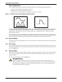
The UPS cabinet is constructed around a steel chassis with removable panels. The top and side panels
are secured to the chassis by screws.
Access to the power terminals, auxiliary terminals blocks and power switches is from the front. Oper-
ational status and alarm information is provided through the front door operator control panel. Mod-
els 20kVA and below house both the power components and an internal battery. Cooling air enters
the front of the NX and is exhausted out the rear.
1.4.1 System Cabinets
A UPS may comprise a number of cabinets, depending on the design requirements (e.g., UPS cabinet,
external battery cabinet, external bypass cabinet). In general, all the Liebert cabinets used in a particu-
lar installation are of the same height and designed to be positioned side-by-side to form a matching
array.
Refer to 4.0 - Installation Drawings for assistance on positioning the cabinets described below.
1.4.2 10 to 20kVA UPS
The UPS consist of a single cabinet, which uses typically forty (40) 12V battery blocks, fitted inter-
nally and connected in series to provide a nominal battery voltage.
The UPS may be shipped without
the batteries fitted.
An extended battery option is available. This comprises a separate cabinet containing additional bat-
teries that can be connected to the UPS to increase its battery run time.
1.4.3 Moving the Cabinets
Ensure that the UPS weight is within the designated surface weight loading of any handling equip-
ment. See Table 33.
UPS and optional cabinets (battery cabinets, top cable entry cabinets, etc.) can be handled by means
of a forklift or similar equipment.
The UPS cabinet also can be moved short distances by its casters.
!
WARNING
Ensure that any equipment used to move the UPS cabinet has sufficient lifting capacity.
The UPS is fitted with casters. Take care to prevent the NX from moving when unbolting the
unit from its shipping pallet. Ensure that adequate personnel and lifting aids are available
when removing the shipping pallet.
NOTE
Care must be taken when maneuvering units fitted with batteries. Keep such moves to a
minimum.

Single Module UPS Installation
6
1.4.4 Clearances
The Liebert NX has no ventilation grilles at either side of the UPS. To enable routine tightening of
power terminations within the UPS, in addition to meeting any local regulations, Liebert recom-
mends providing adequate clearance in the front of the equipment for unimpeded passage of person-
nel with the doors fully opened. It is important to leave of 150mm (5.9") clearance behind the UPS to
permit adequate circulation of air coming out of the unit.
1.4.5 Access
The component layout of the UPS supports front and top access while servicing, diagnosing and
repairing the UPS, thus reducing the space requirement for side and rear access.
1.4.6 Final Positioning
The UPS cabinets are fitted with casters on the base to allow ease of movement and positioning.
When the equipment has been finally positioned, ensure the adjustable feet are set so that the UPS
will remain stationary and stable.
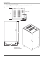
1.4.7 Floor Anchoring
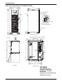
Diagrams in 4.0 - Installation Drawings show the location of the holes in the base plate through
which the equipment may be bolted to the floor. If the equipment is to be installed on a raised floor it
should be mounted on a pedestal suitably designed to accept the equipment point loading. Refer to the
base view Figure 18 to design this pedestal.
1.4.8 Cable Entry
Cables can enter the Liebert NX UPS and battery cabinet from below. Cable entry is made possible by
removing a blanking piece fitted at the bottom of equipment to reveal the cable entry hole.
1.5 External Protective Devices
Circuit breakers or other protective devices must be installed in the AC supply, external to the UPS.
This chapter provides guidelines for qualified installers who must have knowledge of local wiring
practices pertaining to the equipment to be installed.
1.5.1 Rectifier and Bypass Input
Overcurrent protection must be installed at the distribution panel of the incoming main supply. The
protection must discriminate with the power cables current capacity and with the overload capacity of
the system (see Table 36). As a guideline, a thermomagnetic circuit breaker, with an IEC 60947-2
trip curve C (normal) for 125% of the current listed in Table 1 is suitable.
Split-Bypass—If a split-bypass is used, install separate protective devices for the rectifier and for
the bypass in the incoming mains distribution panel.
!
WARNING
Casters are strong enough for movement across even surfaces only. Caster failure could occur
if they are subjected to shock loading.
NOTE
Rectifier and bypass input sources must be referenced to the same neutral potential.
NOTE
For IT power systems, four-pole protective devices must be used, external to the UPS, both
upstream of the input distribution panel and downstream (toward the load).

Single Module UPS Installation
7
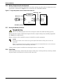
Earth Leakage (RCD):
Any residual current detector (RCD) installed upstream of the UPS input supply must be:
• sensitive to DC unidirectional pulses (Class A)
• insensitive to transient current pulses, and
• must have an average sensitivity, adjustable between 0.3 and 1A.
Figure 1 Residual current circuit breakers (RCCB) symbols
To avoid false alarms, earth leakage monitoring devices when used in systems with split-bypass input
or when used in paralleled UPS configurations, must be located upstream of the common neutral
sinking point. Alternatively, the device must monitor the combined four-wire rectifier and split-
bypass input currents.
The residual earth current introduced by the RFI suppression filter inside the UPS is greater than
3.5mA and less than 300mA. Liebert recommends verifying the selectivity with all other differential
devices both upstream of the input distribution board and downstream (toward the load).
1.5.2 External Battery
The UPS and its associated batteries are protected against overcurrents through a DC compatible dis-
connect device.
1.5.3 UPS Output
Any external distribution board used for load distribution shall be fitted with protective devices that
discriminate with those used at the bypass input to the UPS and with the UPS overload characteris-
tics (see Table 36).
1.6 Power Cables
The cable design must comply with the voltages and currents provided in this section, follow local wir-
ing practices and take into consideration the environmental conditions (temperature and physical
support media).
For cable entry terminal, refer to Figure 19.
!
WARNING
Before starting the UPS, ensure that you are aware of the location and operation of the
external isolators that connect the ups input/bypass supply to the mains distribution panel.
Check that these supplies are electrically isolated and post any necessary warning signs to
prevent their inadvertent operation.

Single Module UPS Installation
8
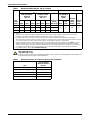
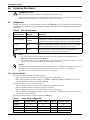
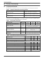
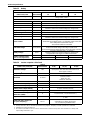
Table 1 Maximum steady state AC and DC currents
UPS
Rating
(kVA)
Nominal Current, Amps Busbar Stud Size
Input Mains Current
1,2
With Full Battery
Recharge
3ph + N
Output Current
2
at Full Load
3ph + N
Battery at
End of
Discharge
Input/Output/
Bypass
Cables
External
battery
Cables
(Bolts)
Torque
Load
(Nm) 380V 400V 415V 380V 400V 415V Bolt
Hole
Dia.
(mm)
10 22 21 20 15 14 13 22
M6 6 M6 515 33 32 31 22 21 20 33
20 44 43 42 30 29 28 44
1. Input mains current listed for common rectifier and bypass AC input. For split input the rectifier current is 94% of the currents
listed.
2. Non-linear loads (switch mode power supplies) affect the design of the output and bypass neutral cables. The current
circulating in the neutral cable may exceed the nominal phase current. A typical value is 1.5 In.
3. Protective earth cable: Connect each cabinet to the main ground system must follow the most direct route possible.
The earth conductor shall be sized in accordance with the AC supply fault rating, cable lengths and type of protection. Typical
cross sectional areas are 2.5mm
2
(10kVA), 6mm
2
(15kVA), 10mm
2
(20kVA), as per AS / IEC 60950-1
4. When sizing battery cables, a maximum volt drop of 4 VDC is permissible at the current ratings given in Table 1. The load
equipment is generally connected to a distribution board containing individually protected busbars rather than connected
directly to the UPS output. The output cables from paralleled units to the parallel distribution bus should be of same length so
as to optimise the sharing of current. Do not form coils, so as to minimise the formation of electromagnetic interference.
5. For terminal location – refer to 4.0 - Installation Drawings)
!
WARNING
Failure to follow adequate earthing procedures may result in electromagnetic interference or
in hazards involving electric shock and fire.
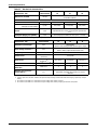
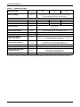
Table 2 Distance from floor to connection point on the equipment
UPS
UPS 10-20 kVA
Minimum Distance
mm (in.)
Rectifier A.C. Input supply 284 (11-1/5)
Bypass A.C. Input supply 284 (11-1/5)
UPS Output A.C. 369 (14-1/2)
Battery Power 369 (14-1/2)
Auxiliary cables: Monitor board (U2) 1104 (43-1/2)

Single Module UPS Installation
9
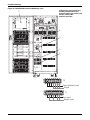
1.6.1 Cable Termination
Once the equipment has been finally positioned and secured, connect the power cables as described in
the following procedure.
Refer to the appropriate cable connection drawing in 4.0 - Installation Drawings.
1. Verify that the UPS equipment is isolated from its external power source and all the UPS power
isolators are open. Check that these supplies are electrically isolated and post any necessary
warning signs to prevent their inadvertent operation.
2. Open the door to the UPS cabinet and remove the front protective cover to gain access to the
connections bars.
3. Connect the safety earth and any necessary bonding earth cables to the copper earth busbar
located on the floor of the equipment below the power connections. All cabinets in the UPS must
be connected to the user’s ground connection.
Identify and make power connections for incoming cables according to one of the two procedures
below, depending on the type of installation.
Common Input Connections
4. For common bypass and rectifier inputs, connect the AC input supply cables between the mains
distribution panel and the UPS input (mA-mB-mC-N terminals) and tighten the connections to
5Nm (M6 Bolt). Ensure correct phase rotation.
Split-Bypass Connections
5. If a split-bypass configuration is used, connect the AC input supply cables to the rectifier input
busbars (mA-mB-mC-N terminals) and the AC bypass supply cables to the bypass input
(bA-bB-bC-N terminals) and tighten the connections to 5 Nm (M6 Bolt). Ensure correct phase
rotation.
Output System Connections
6. Connect the system output cables between the UPS output (oA-oB-oC-N terminals) and the
critical load and tighten the connections to 5 Nm (M6 Bolt). Ensure correct phase rotation.
NOTE
The operations described in this section must be performed by authorised electricians or
qualified technical personnel. If you have any difficulties, do not hesitate to contact our
Customer Service and Support Department. See the back page of this manual for contact
information.
NOTE
The earthing and neutral bonding arrangement must be in accordance with local and national
codes of practice.
NOTE
For split-bypass operation, ensure that the linking busbars between bypass and rectifier input
are removed.
The AC input and the AC bypass supplies must be referenced to the same neutral point.
!
WARNING
If the load equipment will not be ready to accept power on the arrival of the commissioning
engineer, ensure that the system output cables are safely isolated at their ends.

Single Module UPS Installation
10
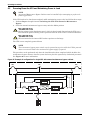
Internal UPS Battery Connection
7. The battery consists of a series string connection of 5 x 8 (or 10) x 12V 6-cell battery blocks.
a. Ensure that the 8 (or 10) battery blocks in each tier (tray) are interconnected.
b. Connect the positive, neutral and negative cables to the UPS terminals.
c. Plug in the cables between the tiers.
d. Ensure correct polarity battery string series connections (i.e., intertier and
interblock connections are from positive to negative terminals.
8. Refit all protective covers removed for cable installation.
!
WARNING
Hazardous Battery Terminal Voltage 480VDC
Ensure correct polarity of string end connections to the UPS terminals, i.e., positive to
positive, negative to negative and neutral to neutral, but leave these UPS terminal cables
disconnected until connection is authorised by the commissioning engineer.
Ensure correct polarity of string end connections to the battery circuit breaker and from the
battery circuit breaker to the UPS terminals, i.e., positive to positive and negative to negative,
but disconnect one or more battery cell links in each tier.
Do not reconnect these links and do not close the battery circuit breaker before authorised by
the commissioning engineer.

Single Module UPS Installation
11
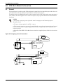
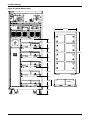
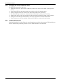
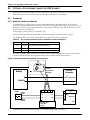
1.7 Control Cables and Communication
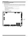
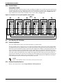
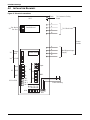
1.7.1 Monitor Board Features
Based on your site’s specific needs, the UPS may require auxiliary connections to manage the battery
system (external battery circuit breaker, battery temperature sensor), communicate with a personal
computer or provide alarm signaling to external devices or for Remote Emergency Power Off (REPO).
The monitor board, arranged for this purpose, is located on the rear of the operator access door. The
main features are:
• Input and Output dry contacts signal (one pair of contacts of relay)
• Emergency Power Off control (EPO)
• Environmental parameter input interface
• User communication (for data setting and user background monitor)
• Intellislot™ interface
• Modem interface
• Temperature detect interface
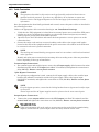
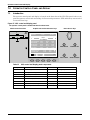
Figure 2 Auxiliary terminal block detail
Intellislot 2
Intellislot 1
Intellislot 3
J1J3
J22
J23
J12
J9
X4
J15
J16
J17
J24
J10J30J26J4J28J25J21
J13
Dry In MBC BCB
BFP INV ACF
EPO
X4 X2 X3
J2
LCD
J8
X7
X6
X5
X4
PWR
Modem
SNMP Card
The black square ( )
on each slot indicates Pin 1.

Single Module UPS Installation
12
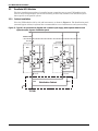
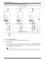
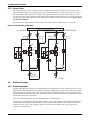
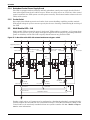
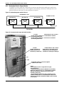
1.8 Dry Contacts
The UPS provides input dry contacts and output dry contacts.
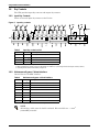
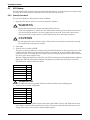
1.8.1 Input Dry Contacts
There are several input dry contacts at the X3 slot.
Figure 3 Input dry contacts
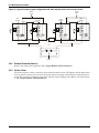
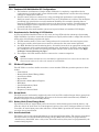
1.8.2 Maintenance Bypass Cabinet Interface
J26 and J30 are the MBC interface.
Table 3 Input dry contacts at X3
Position
Name
Description
J4.1 ENV
3
Battery Room Alarm (NC)
J4.2 BtG Battery Ground Fault Detection (NC)
J4.3 GEN
1,2
On Generator (NO)
J4.4 +12V +12V Power
1 - Must be configured by configuration software before becoming active.
2 - When activated, the charger current can be limited, via software, to a percentage of the full charger current (0-100%).
3 - Activating this feature turns the battery charger off.
Table 4 Maintenance bypass cabinet interface
Position
Name
Description
J26.1 T_IT
1
Input transformer overtemperature (NC)
J26.2 AUX_I Reserved
J26.3 +12V +12V Power
J26.4 GND Power Ground
J30.1 FUSE Reserved
J30.2 F_FAN Fan Fail Alarm (NC)
J30.3 T_OT
1
Output Transformer Overtemperature (NC)
J30.4 AUX_O Reserved
1
- Must be configured by software before becoming active
NOTE
All auxiliary cables must be double insulated. Wire should be 0.5 - 1.5mm
2
(16-20AWG) stranded.
X3
12V
J4 J26 J30 J10
12V
GEN
BtG
ENV
GND
AUX_I
T_IT
FB
GND
F_FAN
FUSE
OL
DRV
12V
AUX_O
T_OT
12V 12V
12V
Page is loading ...
Page is loading ...
Page is loading ...
Page is loading ...
Page is loading ...
Page is loading ...
Page is loading ...
Page is loading ...
Page is loading ...
Page is loading ...
Page is loading ...
Page is loading ...
Page is loading ...
Page is loading ...
Page is loading ...
Page is loading ...
Page is loading ...
Page is loading ...
Page is loading ...
Page is loading ...
Page is loading ...
Page is loading ...
Page is loading ...
Page is loading ...
Page is loading ...
Page is loading ...
Page is loading ...
Page is loading ...
Page is loading ...
Page is loading ...
Page is loading ...
Page is loading ...
Page is loading ...
Page is loading ...
Page is loading ...
Page is loading ...
Page is loading ...
Page is loading ...
Page is loading ...
Page is loading ...
Page is loading ...
Page is loading ...
Page is loading ...
Page is loading ...
Page is loading ...
Page is loading ...
Page is loading ...
Page is loading ...
Page is loading ...
Page is loading ...
Page is loading ...
Page is loading ...
Page is loading ...
Page is loading ...
Page is loading ...
Page is loading ...
Page is loading ...
Page is loading ...
Page is loading ...
Page is loading ...
-
 1
1
-
 2
2
-
 3
3
-
 4
4
-
 5
5
-
 6
6
-
 7
7
-
 8
8
-
 9
9
-
 10
10
-
 11
11
-
 12
12
-
 13
13
-
 14
14
-
 15
15
-
 16
16
-
 17
17
-
 18
18
-
 19
19
-
 20
20
-
 21
21
-
 22
22
-
 23
23
-
 24
24
-
 25
25
-
 26
26
-
 27
27
-
 28
28
-
 29
29
-
 30
30
-
 31
31
-
 32
32
-
 33
33
-
 34
34
-
 35
35
-
 36
36
-
 37
37
-
 38
38
-
 39
39
-
 40
40
-
 41
41
-
 42
42
-
 43
43
-
 44
44
-
 45
45
-
 46
46
-
 47
47
-
 48
48
-
 49
49
-
 50
50
-
 51
51
-
 52
52
-
 53
53
-
 54
54
-
 55
55
-
 56
56
-
 57
57
-
 58
58
-
 59
59
-
 60
60
-
 61
61
-
 62
62
-
 63
63
-
 64
64
-
 65
65
-
 66
66
-
 67
67
-
 68
68
-
 69
69
-
 70
70
-
 71
71
-
 72
72
-
 73
73
-
 74
74
-
 75
75
-
 76
76
-
 77
77
-
 78
78
-
 79
79
-
 80
80


Emerson Liebert NXE 20kVA User manual
- Type
- User manual
- This manual is also suitable for
Ask a question and I''ll find the answer in the document
Finding information in a document is now easier with AI
Related papers
Other documents
-
Minuteman ED6000RMXFMR User manual
-
Liebert Series 300 Installation, Operaton & Maintenance Manual
-
Powerware 9305 HS Series User and Installation Manual
-
-
GE 20 User manual
-
-
AEG Protect 2.33 2.0 User manual
-
-
-