Page is loading ...

INSTRUCTION MANUAL
MODEL 2099-42 CLOCK GENERATOR
Data, drawings, and other material contained herein are proprietary to Cross Technologies,
Inc., but may be reproduced or duplicated without the prior permission of Cross
Technologies, Inc. for purposes of operating the equipment.
When ordering parts from Cross Technologies, Inc., be sure to include the equipment
model number, equipment serial number, and a description of the part.
First Edition October 2005 Rev A 10/27/05
CROSS TECHNOLOGIES, INC.
6170 SHILOH ROAD
ALPHARETTA, GEORGIA 30005
(770) 886-8005 (PHONE)
(770) 886-7964 (FAX)
1-888-900-5588 (TOLL FREE)
www.crosstechnologies.com
2099-42 manual Rev. A Page 1 10/27/2005

INSTRUCTION MANUAL
2099-42 CLOCK GENERATOR
TABLE OF CONTENTS PAGE
Warranty ...................................................................... 2
1.0 General............................................................................. 3
1.1 Equipment Description........................................ 3
1.2 Technical Characteristics........................................ 4
2.0 Installation ...................................................................... 5
2.1 Mechanical ........................................................... 5
2.2 Controls and Indicators.......................................... 5
2.3 Input / Output Signals ........................................ 5
2.4 Jumper Settings ................................................... 5
2.5 Installation / Operation .......................................... 6
2.5.1 Initial Operation ......................................... 6
2.5.2 Switch S1...................................................... 6
2.5.3 Selecting Clock Frequencies....................... 6
2.5.4 Selecting 10 MHz Interface Parameters.... 6
3.0 Circuit Description......................................................... 10
3.1 Block Diagram Description ................................... 10
WARRANTY - The following warranty applies to all Cross Technologies, Inc. products.
All Cross Technologies, Inc. products are warranted against defective materials and
workmanship for a period of one year after shipment to customer. Cross Technologies,
Inc.’s obligation under this warranty is limited to repairing or, at Cross Technologies, Inc.’s
option, replacing parts, subassemblies, or entire assemblies. Cross Technologies, Inc. shall
not be liable for any special, indirect, or consequential damages. This warranty does not
cover parts or equipment which have been subject to misuse, negligence, or accident by the
customer during use. All shipping costs for warranty repairs will be prepaid by the
customer. There are not other warranties, express or implied, except as stated herein.
CROSS TECHNOLOGIES, INC.
6170 SHILOH ROAD
ALPHARETTA, GEORGIA 30005
(770) 886-8005 (P
HONE)
(770) 886-7964 (FAX)
1-888-900-5588 (T
OLL FREE)
www.crosstechnologies.com
2099-42 manual Rev. A Page 2 10/27/2005

MODEL 2099-42 CLOCK GENERATOR
SECTION 1 GENERAL
1.1 Equipment Description- The Model 2099-42 Clock Generator provides two RS422 clock signals
selectable from 256, 192, 128, 96 or 64 kHz locked to an external 10 MHz reference and generated from a
12.288 MHz VCXO. Level detection circuitry provides an alarm signal if the external 10 MHz signal is
removed and automatic switching tunes the VCXO in the PLL to 12.28800 MHz until the 10 MHz clock is
restored. LEDs indicate PLL and Level alarms, Manual operation, and selection of internal or external (lock to
10 MHz) control of the VCXO. A front panel switch manually selects internal or external (lock to 10 MHz)
control of the VCXO. Diodes on the DC inputs allow operation from redundant power supplies. An open
collector indicates Manual operation and relay contacts indicate a major alarm due to loss of PLL lock or 10
MHz reference. The unit is housed in an aluminum extrusion chassis and can be mounted on an 1 3/4”, rack
panel (Option -R). A 115 VAC wall power supply provides DC power to the 2099-42.
20 99-42 CLOCK GENERATOR
C
ROSS
T
ECHNOLOGIES, INC.
EXT. AUTO INT. INT FREQ.
INT/
EXT
MAN
PLL
ALM
REF
ALM
MODE
MONITOR
RS422
CLOCK
OUT
10
MHZ IN
DIVI-
DER
PLL
LEVEL
DET..
AUTO
EXT
INT
INT / EXT
SELECT
VCXO INT.
FREQ.
12.288
MHZ VCXO
A
2099-42 BLOCK DIAGRAM
B
DIVI-
DER
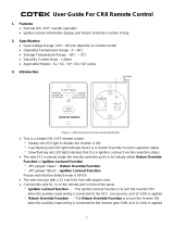
FIGURE 1.1 2099-42 Clock Generator Block Diagram and Front Panel
2099-42 manual Rev. A Page 3 10/27/2005

1.2 Technical Characteristics
TABLE 1.0 2099-42 CLOCK GENERATOR SPECIFICATIONS
Characteristics Specifications*
10 MHz Input Characteristics
Input level 0.5 TO 1.5 V P-P (-4 to +6 dBm into 75 ohms),
Input Impedance 75 or > 2 K, selectable
Clock Output Characteristics
Level RS422
Data Rate 64, 96, 128, 192, 256 kB/s selectable, 2 separate outputs
Stability, Ext Ref. Same as reference
Stability, Int. Ref. ± 50 ppm
Jitter 1 degree
Controls and Indicators
Int/AUTO/Ext Switch Switches between internal and external (lock to 10 MHz) control of
VCXO or AUTO select
Int. Freq Adjusts frequency of internal VCXO when not locked to external 10 MHz
INT/EXT LED LED lights RED if VCXO controlled internally, Green if locked to
external 10 MHz
MAN. LED LED lights RED when Int/AUTO/Ext Switch not in AUTO
PLL ALM LED LED lights RED when phase lock loop is unlocked if switch in Auto or
Ext Ref
REF ALM LED LED lights GREEN when external 10 MHz reference is present, RED if
removed (< 0.2 Vp-p)
Other
Size, Bench Top 4.7” wide X 1.75” high X 12.5” deep
Size, Rack Mount (-R) 19 inch standard chassis 1.75”high X 13.0” deep (Option -R)
Power +15VDC, 180 ma; -15VDC, 60ma; via 115 VAC wall power supply
*+10 to +40 degrees C; Specifications subject to change without notice
2099-42 manual Rev. A Page 4 10/27/2005

2.0 Installation
2.1 Mechanical - The 2099 PCB is packaged in an aluminum extrusion. The 2099 can be mounted on a
1 3/4” X 19” panel (option -R) that can be mounted to a rack using the 4 holes at the ends. The unit derives ±
15V from the wall power supply. Option -C is the unit without power supply for use with external switching
power supply, Model 2000-01. See Figure 2.1
FRONT SCREWS (4EA,
UNDER FRONT PANEL)
RACK MOUNT PANEL
BACKPLANE
REAR SCREWS
(4EA)
FRONT PANEL
PCB
ASSEMBLY
CROSS
TECHNOLOGIES, INC.
WALL POWER
SUPPLY
EXTRUSION
COVER
FIGURE 2.1 SERIES 2099 ASSEMBLY DRAWING (-R OPTION SHOWN)
2.2 Controls and Indicators - Figure 2.2 shows front panel controls and indicators.
2.3 Input / Output Signals - Figure 2.3 shows the input and output signals to the 2099-42. Table 2.1 is a
description of the connectors and J4 pin functions.
2.4 Jumper Settings - Figure 2.4 and Table 2.2 show jumpers and other on-card controls.
2.4.1 Removing the Printed Circuit Board (PCB) From the Extrusion - To remove and re-install the
printed circuit board (PCB) from the extrusion:
1.)
Always remove power when removing or installing the PCB in to the extrusion.
2.) PCB REMOVAL - Remove four (4) rear panel screws (see Figure 2.1).
3.) Gently pull the backplane and PCB assembly completely out of the extrusion.
4.) PCB INSTALLATION -Make sure the shield goes in the lower channel and the PCB in the next
channel above that in the extrusion.
5.) Gently push the backplane and PCB assembly completely in to the extrusion.
6.) Install four (4) rear panel screws.
2099-42 manual Rev. A Page 5 10/27/2005

2.5 Installation / Operation -
2.5.1 Initial Operation -
1.) If different from factory settings (Table 2.2), set on-card jumpers as desired (Figure 2.4)
2.) Connect the wall power supply to the 2099 and the wall power supply to 115 VAC, 60 Hz (Fig. 2.1)
3.) Connect a 1 V P-P 10 MHz signal to J1,10 MHz SIGNAL IN (Figure 2.1, Figure 2.3)
4.) Be sure S1 is in the center (AUTO) position (Figure 2.2)
5.) Be sure DS1 and DS4 are off and DS2 and DS3 are green (Figure 2.2).
6.) If needed, R20 can be adjusted (Figure 2.2) to SLIGHTLY adjust the internal VCXO frequency with
S1 in the INTERNAL REF position and monitoring TP1. ALWAYS be sure S1 is in AUTO (center) for
normal operation.
2.5.2 Switch S1 (Figure 2.2) - S1 selects between Internal Ref / AUTO / External Ref and operates as follows:
External Reference - This is a manual over ride of the AUTO position which forces the 2099-42 to
always control the internal VCXO by locking it to the external 10 MHz reference. If in this position and the 10
MHz is removed, the PLL will lose lock and may force the internal VCXO to the high or low rail which causes
it to be up to plus or minus 1.2 kHz from center frequency. No auto switch over to internal control of the VCXO
will occur in this mode. The front panel potentiometer, R20 does NOT control the VCXO in this mode. Normal
operation in this mode will have DS1 red, DS2 and DS3 green, and DS4 off (Figure 2.2).
AUTO - This forces the 2099-42 to always control the internal VCXO by locking it to the external 10
MHz reference if it is present. If in this position and the 10 MHz is removed, the PLL will lose lock and will
force the internal VCXO to have the frequency set by front panel potentiometer, R20. R20 DOES control the
VCXO in this mode if it has automatically switched to Internal. Normal operation in this mode will have DS1
and DS4 off and DS2 and DS3 green (Figure 2.2).
Internal Reference - This is a manual over ride of the AUTO position which forces the 2099-42 to
always control the internal VCXO by front panel potentiometer, R20. R20 is a ten turn potentiometer which can
control the VCXO by up to plus or minus 300 Hz from center frequency. If the 10 MHz external reference is
present, the PLL Alarm LED, DS4 does not generally light in this mode but will flash occasionally, the rate of
which is a rough indication of the offset of the VCXO from the reference frequency. The slower the rate of the
flash, the closer the VCXO frequency is to the 10 MHz reference. No auto switch over to internal control of the
VCXO will occur in this mode. As mentioned previously, the front panel potentiometer, R20 DOES control the
VCXO in this mode. Normal operation in this mode will have DS1 red, DS2 red, DS3 green, and DS4 off and
occasionally red for short flashes (Figure 2.2).
2.5.3 Selecting Clock Frequencies - The output clock frequencies are selected by the jumper on JP4 for
Clock A and JP5 for Clock B. Setting this jumper closest to the front of the PCB selects 256, then moving it to
the rear selects 192, 128, 96 and 64. The jumper position closest to the back of the PCB is not used.
2.5.4 Selecting 10 MHz Interface Parameters - Jumper JP2 selects the input termination of the
external 10 MHz reference to either 75 termination (JP2 in DOT, factory setting) or 2 K (JP2 in NON-
DOT).
2099-42 manual Rev. A Page 6 10/27/2005

2099-42 CLOCK GENERATOR
CROSS TECHNOLOGIES, INC.
EXT. AUTO INT. INT FREQ.
INT/
EXT
MAN
PLL
ALM
REF
ALM
MODE
MONITOR
J1 - Buffered
output monitor of
the 12.288 MHz
internal VCXO
S1 - EXT. / AUTO / INT.- Manually forces output clock frequency
to be locked to EXTERNAL reference or controlled by
INTERNAL VCXO. In AUTO the output clock frequency is locked
to the external reference unless it is remove when automatic
switchover to the internal VCXO occurs.
DS2 - EXTERNAL /
INTERNAL REF LED
- Lights GREEN if 10
MHz external
reference controls
output clock
frequency, RED if the
internal VCXO alone
does.
DS1 - MANUAL
LED - Lights RED
when S1 is not in
AUTO.
DS4 - PLL ALARM LED -
Lights RED when 10 MHz
external reference is removed
(<0.2 Vp-p) or VCXO is
defective. If S1 is in
INTERNAL REF and 10 MHz
reference is present, DS4 will
light occasionally depending
on how far off in frequency the
VCXO is set from locking to it.
DS3 - EXTERNAL
REFERENCE
PRESENT LED -
Lights GREEN when
10 MHz external
reference is present
and RED if below 0.4
Vp-p
R20 - INTERNAL
REFERENCE
FREQUENCY
ADJUSTMENT Ten
turn potentiometer that
adjusts the internal
VCXO to 12.288000
MHz when in the
INTERNAL
REFERENCE mode.
FIGURE 2.2 2099-42 Front Panel Controls and Indicators
FIGURE 2.3 2099 Inputs and Outputs
J2
J4 - I/O BARRIER STRIP - Provides connections for
audio, data, alarm signals, etc. Pin numbers are as
shown upside down on the connector. See Table 2.1
J2 - DC IN - The
+15 VDC AND -15
VDC regulated DC
voltage from the
wall power supply
-15 +15
GND
J1 - BNC IN/OUT - Signal from pin 2 or 3 (as
set by strap beside J1) of PCB which is for
subcarrier, video, IF and RF signals.
JP1 - J1 OUTPUT TERMINATION
TERM = 75 TERMINATION
2 - 3 = NO 75 TERMINATION
> 2K impedance
1 2 3
JP1
TERM
J4
1 2 3 4 5 6 7 8 9 10 11 12 13 14 15 16 17 18
2099-42 manual Rev. A Page 7 10/27/2005

TABLE 2.1 IN
NPUT AND OUTPUT SIGNALS
TABLE 2.1 INPUT AND OUTPUT SIGNALS
TABLE 2.1 IN
PUT AND OUTPUT SIGNALS
CONNECTOR
GENERAL FUNCTION
2099 FUNCTION COMMENTS
J1 10 MHz INPUT 0.5 TO 1.5 V P-P (-4 to +6 dBm into 75 ohms)
J2 DC IN ± 15 VDC, 3PIN MINI-DIN
J3 PCB EDGE CONNECTOR INTERNAL USE
J4 - PIN
1 GROUND
275 or 2 K, 10MHz Signal In Impedance electable by jumper JP1 on rear panel)
3NOT USED
4 RS422 Clock A Out (+) One end of RS422 Clock A output
5 RS422 Clock A Out (-) One end of RS422 Clock A output
6NOT USED
7NOT USED
8 +15 VDC Backup In 180 ma max,
9 +15 VOLTS. 180 ma max, from J2 Main Power Supply
10 MAJOR Alarm relay output Open or short (selectable) to pin 12 if PLL alarm or no 10 M
H
11 -15 VOLTS 60 ma max, from J2 Main Power Supply
12 MAJOR Alarm relay output Open or short (selectable) to pin 10 if PLL alarm or no 10 M
H
13 NOT USED
14 -15 VDC Backup In 60 ma max
15 MANUAL ALARM OPEN COLLECTOR Shorts to ground (+30 VDC,100 ma max) if S1 not in AUTO
16 RS422 Clock B OUT (+) One end of RS422 Clock B output
17 RS422 Clock B OUT (-) One end of RS422 Clock B output
18 GROUND
TABLE 2.1 2099-42 Inputs and Outputs
2099-42 manual Rev. A Page 8 10/27/2005

TAB
LLE 2.2 JUMPER DESCRIPTION
TABL
E 2.2 JUMPER DESCR
RIPTION
TABLE 2.2 JUMPER DESCR
IPTION
TABLE 2.2 JUMPER DESCRIPTION
JP# Description Dot Non-dot Normal COMMENTS
JP3 ALARM RELAY POSITION NO NC DOT SELECTS NON ENERGIZED (No Alarm) POSITION OF MAJOR ALARM RELAY CLO
JP4 CLOCK B FREQUENCY N/A N/A N/A JUMPER POSITION SELECTS 64 TO 256 CLOCK FREQUENCY, CH A
JP5 CLOCK A FREQUENCY N/A N/A N/A JUMPER POSITION SELECTS 64 TO 256 CLOCK FREQUENCY, CH B
TABLE 2.2 JUMPER DESCRIPTIONS
K1
R20 VCXO ADJ.
DS2 EXT/INT CLK
2
5
6
192
128
96
64
N/U
S1
JP3
JP4
JP5
CLOCK A SELECT
DS1 MANUAL
DS4 PLL ALARM
DS3 REF PRES
2
5
6
192
128
96
64
N/U
CLOCK B SELECT
TP1
MON
TP2 GND
ALARM RELAY CONTACTS
FIGURE 2.4 2099-42 On-Card Jumpers and Controls
2099-42 manual Rev. A Page 9 10/27/2005

3.0 Circuit Description
3.1 Block Diagram Discussion - 2099-42 (Figure 3.1) - The 10 MHz external reference signal goes to buffer
amplifier U15 and then to U1 which squares up the incoming 10 MHz signal. This reference signal then goes to
the synthesizer IC U2. U2 is programmed by controller U3 which provides data required for the synthesizer to
function. The VCXO U5 provides the other input signal into the synthesizer U2. This is controlled through a
switch consisting of U10 which determines whether the PLL is closed through loop amplifier U4 or if the
frequency of the VCXO is determined by the front panel potentiometer R20 which sets the VCXO frequency
when phase lock is broken or the external reference frequency has been removed. The output of U5, the VCXO
also goes through buffer U6 and Q2 to a front panel test point TP1 for monitoring this frequency. The
12.288 Mhz output of the VCXO also goes to divider U9, U11, and U12. The outputs of U11 and U12 provide
the clock signals at 64, 128, 256, 96, and 192 kHz. These signals go to jumpers JP4 and JP5 which are used to
select the desired output clock frequency. These signals go to RS422 driver U14 to provide the clock A and
clock B RS422 outputs.
The external 10 MHz reference frequency also goes to buffer amplifier U7 which drives peak detector
CR8 and then goes to op amp U8, the output of which provides a +5 signal if the 10 MHz signal is present and a
0 volt signal if not present. This logic signal goes to switch S1 which selects manual, internal, external, or
automatic mode. The output of S1 drives analog switch U10 through which the controls for the VCXO are
routed. The output of S1 also goes to the manual indication LED DS1 and U6, a buffer amplifier which drives
open collector output through Q1. The reference present signal out of U8 also goes to U13 which drives the
reference alarm LED DS3. The output of the switch also goes to U13 which drives the red/green
external/internal clock LED DS2. The lock detect output out of U2 goes to diode CR6 which detects the
incoming signal which is a non-DC signal if the loop is out of lock. Presence of this AC signal is detected by
U16 which drives DS4, the PLL alarm LED and also provides the PLL alarm signal which is diode OR'd with
the reference present signal to drive Q3, the FET, which enables the relay K1 which provides contact closures
indicating presence of a major alarm.
Regulators VR2 and VR1 provide +12 and -12 volts from the diode OR'd ±15V input and VR3 provides
+5V for the logic circuitry.
2099-42 manual Rev. A Page 10 10/27/2005

6/25/99 HWW REV B
10
MHZ
IN
TTL
CONV.
U15, U1
PLL
U2,U4
HIGH
TERM
LEVEL
DET.
U7, U8
12.288 MHz Monitor
(Front Panel)
DIVI-
DER
U9,
U11,
U12
256
128
64
192
96
CLOCK A
RS422
U14
4
5
CLOCK B
RS422
16
U14
17
AUTO
V+
V+
EXT
INT
MANUAL
ALARM
UP
U3
INT / EXT
CLOCK
PIN 2
PIN 3
VCXO INT.
FREQ. R20
12.288
MHZ VCXO
+5V
REG
VR3
-15 A
-15B
+15 A
+15B
-12
+12
+5
-12V
REG
VR1
+12V
REG
VR2
U10
U5
U6,
Q2
256
128
64
192
96
INT /EXT
CLOCK
(RED/
GREEN)
REF.
ALM
(RED/
GREEN)
PLL ALM
(RED)
ALARM
PLL LOCK
LEVEL
MANUAL
MANUAL OC
ALARM CC
MANUAL
ALM
(RED)
INT / EXT CLOCK
DS3 DS2 DS1
DS4
S1
JP4
JP5
JP1 JP2
FIGURE 3.1 2099-42 BLOCK DIAGRAM
2099-42 manual Rev. A Page 11 10/27/2005
/