Page is loading ...

77-1541-R21.3 (11/2015) 1 / 8
EN
SERVICE MANUAL
BINKS WREN
®
AIR BRUSHES
MODELS 59-10001 “A”**, 59-10002 “B”, AND 59-10021 “C”**
OPERATING INSTRUCTIONS
READ ALL INSTRUCTIONS BEFORE OPERATING THIS BINKS PRODUCT.
IMPORTANT! DO NOT DESTROY
It is the customer's responsibility to have all operators and service personnel
read and understand this manual.
Contact your local Binks representative for additional copies of this manual.
**Models “A” and “C” are discontinued.
(Shown for component replacement only.)

77-1541-R21.3 (11/2015)2 / 8
EN
DE-ENERGIZE, DEPRESSURIZE,
DISCONNECT AND LOCK OUT ALL POWER
SOURCES DURING MAINTENANCE
Failure to De-energize, disconnect and lock out
all power supplies before performing equipment
maintenance could cause serious injury
or death.
OPERATOR TRAINING
All personnel must be trained before operating
finishing equipment.
EQUIPMENT MISUSE HAZARD
Equipment misuse can cause the equip ment to
rupture, malfunction, or start unexpectedly and
result in serious injury.
KEEP EQUIPMENT GUARDS IN PLACE
Do not operate the equipment if the safety
devices have been removed.
PROJECTILE HAZARD
You may be injured by venting liquids or gases
that are released under pressure, or flying
debris.
PINCH POINT HAZARD
Moving parts can crush and cut. Pinch points
are basically any areas where there are moving
parts.
INSPECT THE EQUIPMENT DAILY
Inspect the equipment for worn or broken parts
on a daily basis. Do not operate the equipment
if you are uncertain about its condition.
In this part sheet, the words WARNING, CAUTION and NOTE are used to
emphasize important safety information as follows:
Hazards or unsafe
practices which could
result in minor personal
injury, product or property
damage.
!
CAUTION
Hazards or unsafe
practices which could
result in severe personal
injury, death or substantial
property damage.
!
WARNING
Important installation,
operation or maintenance
information.
NOTE
Read the following warnings before using this equipment.
READ THE MANUAL
Before operating finishing equipment, read and
understand all safety, operation and
maintenance information provided in the
operation manual.
WEAR SAFETY GLASSES
Failure to wear safety glasses with side shields
could result in serious eye injury or blindness.
NEVER MODIFY THE EQUIPMENT
Do not modify the equipment unless the
manufacturer provides written approval.
IT IS THE RESPONSIBILITY OF THE EMPLOYER TO PROVIDE
THIS INFORMATION TO THE OPERATOR OF THE EQUIPMENT.
FOR FURTHER SAFETY INFORMATION REGARDING BINKS
AND DEVILBISS EQUIPMENT, SEE THE GENERAL EQUIPMENT
SAFETY BOOKLET (77-5300).
KNOW WHERE AND HOW TO SHUT OFF
THE EQUIPMENT IN CASE OF AN
EMERGENCY
PRESSURE RELIEF PROCEDURE
Always follow the pressure relief procedure in
the equipment instruction manual.
NOISE HAZARD
You may be injured by loud noise. Hearing
protection may be required when using this
equipment.
STATIC CHARGE
Fluid may develop a static charge that must be
dissipated through proper grounding of the
equipment, objects to be sprayed and all other
electrically conductive objects in the dispensing
area. Improper grounding or sparks can cause a
hazardous condition and result in fire, explosion or
electric shock and other serious injury.
PROP 65 WARNING
WARNING: This product contains chemicals
known to the State of California to cause
cancer and birth defects or other reproductive
harm.
FIRE AND EXPLOSION HAZARD
Never use 1,1,1-trichloroethane, methylene
chloride, other halogenated hydrocarbon solvents
or fluids containing such solvents in equipment
with aluminum wetted parts. Such use could result
in a serious chemical reaction, with the possibility
of explosion. Consult your fluid suppliers to ensure
that the fluids being used are compatible with
aluminum parts.

77-1541-R21.3 (11/2015) 3 / 8
EN
Proficient use of the air brush is gained only after
you thoroughly know the major parts of the air
brush and how they operate.
THE MECHANICAL CONTROLS
The Trigger Button is the square, chrome-plated
button on top of the air brush. This is a single-action
control in that it controls only the flow of air. Some
air brushes have a double-action trigger button
which controls both the flow of air and the amount
of fluid being sprayed.
The small, Knurled Screw just below the trigger
button limits the movement of the trigger button
and the flow of air. This screw should be turned
down (to the left) as far as it will go. Only when a
spatter or stipple effect is desired should the trigger
button screw be raised to the position just below the
extended trigger button. Experimenting with the
screw in different positions will provide a variety of
lighter to heavier spatter patterns. The color drop-
lets will increase in size as the screw is turned high-
er, cutting down the flow of air.
The Air Intake is located at the bottom of the air
brush in line with the slanted trigger button. Screw
the small end of the air hose to the air intake and
tighten with fingers until snug.
The Fluid Control is located under the front end of
the air brush and protrudes into the nozzle. The
knurled portion of the fluid control opens or closes
the flow of fluid. Turning the control clockwise opens
it wider, counter-clockwise closes it.
The Color Bottle Assembly has a friction connec-
tion which is inserted into the opening at the bottom
of the fluid control (see photo), and is fastened with
a firm push-and-twist motion. Look for a small vent
hole in the lid of the bottle assembly. This hole
should be kept open and free of fluid because if it
becomes clogged, the flow of air into the bottle is
blocked, preventing the flow of color upward into
the fluid control.
The air needed to operate the air brush can be
obtained from portable or larger tank-mounted com-
pressors. The air pressure should be about 38 psi
when the air brush is not spraying; it should drop to
about 30 psi when in operation. Be sure that all
hose connections are tight to prevent leakage.
USE OF THE AIR BRUSH
The colors to be sprayed, or air brushed, should be
thoroughly mixed and free of lumps or pigment or
other impurities. It is wise to strain the fluids
through a piece of nylon stocking as you pour them
into the color bottles. Your colors and paints may
have to be thinned down to permit their flow
through the air brush.
The air brush should be held much like a pencil,
with the index finger operating the trigger button.
The air hose should pass below the thumb and over
the wrist to keep it out of the way.
Air brushing should be done in short strokes, or
bursts. Depress and release the trigger button with
each stroke. This will quickly become a habit.
Now you are ready to start. Choose a dark color to
spray so you can see what is occuring. First, turn
the fluid control counter-clockwise to close it. Hold
the air brush about a half-inch from the paper and
depress the trigger button. Slowly open the fluid
control until a wisp of color appears. It will make a
small dot or, as you slowly move your hand, a small,
fine line. As you open the fluid control wider, move
the air brush back away from the paper and a wider
line will be sprayed. Continue experimenting in this
manner to learn what can be done with the air
brush. The use of stencils or straight edges can
quickly give varied and pleasing effects. Highlights
and depth are created by air brushing some areas
more lightly, or by letting the background colors
show through. Stencils can be used for spraying
many shapes.
TO DISASSEMBLE THE AIR BRUSH
1. Air Inlet Section (see exploded drawing, pg. 3)
a. Remove plunger (11) with special wrench, or a
very small screwdriver, which releases the trig-
ger (3) and spring (14).
b. Remove the housing (10) with special wrench,
or a hex wrench. Pick out washer (13) and
gasket packing (12) with straightened paper
clip.

77-1541-R21.3 (11/2015)4 / 8
EN
When reassembling, dip washer and gasket
in vaseline or clear lubricant, and place on
top of housing and insert preassembled.
NOTE
2. Fluid Control or Nozzle Section (see exploded
drawing, pg. 3)
a. Remove the needle portion of control with
special wrench, or a hex wrench.
b. Remove nut (9) from nozzle portion with larg-
er blade of special wrench.
c. Pick out packing (6) with straightened paper
clip. (Dip in vaseline or clear lubricant when
reassembling.)
If air brush spits moisture, (especially in
humid weather or in an air conditioned
room) a moisture trap is recommended.
NOTE
OPERATION
THINNING FLUIDS
Fluids that may be sprayed with the air brush range
from light, or water-type consistency to heavy, or
enamel-type consistency. It is most desirable that
the fluid be of a viscosity that is sprayable, provides
adequate coverage and yet will not run or sag. To
achieve this, reduction, or thinning of the fluid may
be necessary. When and how to correctly reduce or
thin fluids is a matter of judgement and common
sense.
STRAINING FLUIDS
Since the fluid orifices in the air brush are extremely
small, it is essential that the fluid to be sprayed be
free of foreign particles. It is recommended that flu-
ids be strained through a piece of nylon stocking or
similar mesh cloth before use.
CLEANING
Ninety-five percent of breakdowns in the operation
of the Wren Air Brush are directly due to not keep-
ing the air brush clean at all times, especially after
each use. When using fast-drying fluids, such as lac-
quers, underglazes, etc. which will set up in five to
ten minutes, it may be necessary to clean or
immerse the fluid control end of the air brush in
compatible solvent during intermittent use.

77-1541-R21.3 (11/2015) 5 / 8
EN
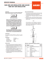
BINKS WREN
®
AIR BRUSHES
MODELS 59-10001 “A”
**
, 59-10002 “B”, AND 59-10021 “C”
**
**
MODELS “A” AND “C” ARE DISCONTINUED – SHOWN FOR COMPONENT REPLACEMENT ONLY.
ITEM
NO.
PART
NO.
DESCRIPTION QTY.
1
HANDLE (5-137) 1
2
BODY (WREN “B”) (59-2)
1
3 59-3 TRIGGER BUTTON 1
4
*
AIR VALVE SCREW (59-4) 1
5
BODY (WREN “C”) (59-5) 1
6 59-8
*
FLUID CONTROL PACKING 1
7 59-9 FLUID CONTROL ASSEMBLY (WREN “A” .0292) 1
8 59-10
FLUID CONTROL ASSEMBLY (WREN “B” .052) 1
9
*
PACKING RETAINER NUT (59-13) 1
10 59-20 AIR VALVE HOUSING 1
11
*
• AIR VALVE PLUNGER 1
12
*
AIR VALVE PACKING 1
13
*
AIR VALVE WASHER (59-23) 1
14
*
AIR VALVE SPRING (59-24) 1
15
*
WRENCH-SPECIAL (59-83) (NOT SHOWN) 1
16 59-101
FLUID CONTROL ASSEMBLY (WREN “C” .0595) 1
NOT AVAILABLE AS INDIVIDUALLY PURCHASED PARTS.
*
PARTS INCLUDED IN 59-102 REPAIR KIT.
MODELS “B” OR “C” CONTROLS ARE INTERCHANGEABLE. THE “A” CONTROL CAN ALSO BE
USED ON THE “B” AND “C” BODY. DO NOT USE “B” OR “C” CONTROL WITH “A” BODY.
• IMPORTANT–ALWAYS REMOVE NO. 59-21 PLUNGER BEFORE REMOVING
NO. 59-20 HOUSING.
3
4
5
1
12
13
10
11
7
8
96
16
2
14

77-1541-R21.3 (11/2015)6 / 8
EN
ACCESSORIES
SIPHON BOTTLE ASSEMBLIESHOSES
59-31
1/2 oz.
59-81
2 oz.
59-30
1/4 oz.
59-10006 WREN “B” SET
Includes air brush, 1/4, 1/2 and 2 fluid oz.
color bottle assemblies and 59-60 (6') light-
weight vinyl hose with connections, packed
in an attractive, clear plastic case.
59-60 Vinyl Hose Assembly 6'
59-61 Braided Hose Assembly 6'

77-1541-R21.3 (11/2015) 7 / 8
EN
TROUBLESHOOTING
BINKS WREN
®
AIR BRUSHES – MODELS 59-10001 “A”, 59-10002 “B”, AND 59-10021 “C”
COMPLAINT CAUSE REMEDY
AIR BRUSH DOES
NOT SPRAY
Insufficient air supply. Increase air supply–requires 28 psi to operate “A” brush,
and 30 psi to operate “B” and “C” brushes.
Clogged vent hole in cover of
bottle.
Carefully clean out hole with pin.
Clogged fluid control. Disassemble uid control and soak in compatible solvent;
clean out soft paint with care.
Clogged air passage. Remove air valve plunger with a jeweler’s screwdriver, or
the screwdriver end of the 59-83 wrench, before
attempting to remove housing. Clean out passages with
broomstraw or similar probe. Blow air through to ensure
orices are open.
Excessively heavy fluid. Reduce uid viscosity with compatible solvent.
AIRBRUSH SPITS OR
SPURTS
Air is bypassing the packing in
uid control.
Remove the uid control retainer nut and packing with
the 59-83 wrench or small, wide-blade screwdriver.
Replace packing, and also retainer nut, if necessary.
TRIGGER BUTTON
WON’T FUNCTION
PROPERLY
Trigger button spring has lost
its tension.
Remove air valve plunger with a jeweler’s screwdriver, or
the screwdriver end of the 59-83 wrench, which releases
trigger button and spring. Replace spring. (Temporary
repair can be made by stretching the spring).
Note: Model 59-102 Repair Kit is available. It contains the special tool, 59-83 wrench, for complete disassembly of
the air brush and an assortment of parts.

77-1541-R21.3 (11/2015)8 / 8
EN
Finishing Brands reserves the right to modify equipment specications without prior notice.
DeVilbiss
®
, Ransburg
®
, BGK
®
, and Binks
®
are registered trademarks of Carlisle Fluid Technologies, Inc.,
dba Finishing Brands. ©2015 Carlisle Fluid Technologies, Inc., dba Finishing Brands. All rights reserved.
WARRANTY POLICY
Binks products are covered by Finishing Brands one year materials and workmanship limited
warranty. The use of any parts or accessories, from a source other than Finishing Brands,
will void all warranties. For specic warranty information please contact the closest
Finishing Brands location listed below.
Binks is part of Finishing Brands, a global leader in innovative
spray nishing technologies. For technical assistance or to locate
an authorized distributor, contact one of our international sales
and customer support locations below.
USA/Canada
www.binks.com
Tel: 1-800-992-4657
Fax: 1-888-246-5732
United Kingdom
www.nishingbrands.eu
Tel: +44 (0)1202 571 111
Fax: +44 (0)1202 573 488
China
www.nishingbrands.com.cn
Tel: +8621-3373 0108
Fax: +8621-3373 0308
Mexico
www.carlisleft.com.mx
Tel: 011 52 55 5321 2300
Fax: 011 52 55 5310 4790
France
www.nishingbrands.eu
Tel: +33(0)475 75 27 00
Fax: +33(0)475 75 27 59
Japan
www.ransburg.co.jp
Tel: 081 45 785 6421
Fax: 081 45 785 6517
Brazil
www.devilbiss.com.br
Tel: +55 11 5641 2776
Fax: 55 11 5641 1256
Germany
www.nishingbrands.eu
Tel: +49 (0) 6074 403 1
Fax: +49 (0) 6074 403 281
Australia
www.nishingbrands.com.au
Tel: +61 (0) 2 8525 7555
Fax: +61 (0) 2 8525 7500
/